- 1School of Engineering and Design, Technical University of Munich, Munich, Germany
- 2Department of Electrical and Computer Engineering, Technical University of Munich, Munich, Germany
- 3Department of Informatics, Technical University of Munich, Munich, Germany
- 4Department of Physics, Technical University of Munich, Munich, Germany
The Munich Orbital Verification Experiment (MOVE) is a CubeSat student project housed at the Scientific Workgroup for Rocketry and Spaceflight at the Technical University of Munich. MOVE-III is the fourth CubeSat under development, and the first 6U mission of the MOVE project that will carry a dedicated scientific payload in orbit. The mission aims at acquiring in-situ observations of sub-millimetre space debris and meteoroids in Low Earth Orbit, with the objective of compiling a dataset of flux, as well as object mass and velocity measurements that can be used for the validation of the small object estimates of space debris models and support further studies related to the characterisation of the space environment. The MOVE-III CubeSat employs the MOVE-BEYOND platform and is planned to carry three Debris Density Retrieval and Analysis (DEDRA) plasma ionization sensors. The Preliminary Design Review has been completed in early 2022, with the next milestone being the Critical Design Review, planned for 2023. The paper elaborates on the scientific objectives of the mission and the expected data products, provides an overview of the detector operation principle and presents the overall system architecture, the platform configuration and the subsystem interaction. Considerations on the debris mitigation aspects of the mission are additionally discussed.
1 Introduction
On the fourth of October 1957, Sputnik 1, the first artificial satellite, was launched into Low Earth Orbit (LEO) by the Soviet Union. Since then, numerous artificial objects have accumulated in orbits around the Earth, with their numbers constantly increasing. A great deal of these objects are space debris: satellites which are no longer functional, used rocket bodies, mission-related objects but also fragments from break-up events, accidental or deliberate collisions and explosions, and even particles from deterioration of spacecraft components or solid rocket motor firings. In order to ensure a safe and sustainable future use of space, the Inter-Agency Space Debris Coordination Committee (IADC) published the IADC Space Debris Mitigation Guidelines in 2002, in which LEO as well as the Geostationary Orbit (GEO) are declared as Protected Regions (IADC, 2020). Missions targeting these regions are subject to space debris mitigation requirements and international standards such as the ISO 24113 (ISO, 2019), the IADC Protection Manual (IADC, 2018a), or the ESA Space Debris Mitigation Compliance Verification Guidelines (ESA, 2015a).
Large space debris objects inarguably pose an immediate threat to both manned and unmanned missions. A collision with a large object is likely to be catastrophic [a collision is considered catastrophic when the Energy-to-Mass Ratio threshold of 40 J/g is exceeded (McKnight and Hoyle, 1992; IADC, 2018b)] and it threatens ending a mission prematurely, as well as increasing the space debris population, which consequently increases the impact risk for future missions. As of today, ground radar and optical systems are able to track objects with approximate sizes of 5–10 cm in LEO and 50–100 cm in GEO, and catalogues of these objects are created by Space Surveillance Networks [Space Surveillance Networks (SSNs)]. The orbits of the catalogued objects can therefore be predicted, which allows estimating the collision risk of an operational satellite with trackable space debris and, if applicable, plan a collision avoidance manoeuvre. As of today, more than 30,000 debris objects are regularly tracked by SSNs and maintained in catalogues (ESA, 2022d). However, the vast majority of the space debris population is much smaller and cannot be seen or systematically tracked using ground surveillance infrastructures. Statistical models estimate that more than 130 million objects larger than 1 mm are currently in orbit (ESA, 2022d). While an impact with a small space debris object (≤1 cm) is generally unlikely to trigger a catastrophic collision, it may still fragment the spacecraft, damage or interrupt the operation of a subsystem (solar panels, antennas etc.), or penetrate an on-board energy source or propellant tank triggering an on-orbit explosion. More than 630 confirmed fragmentation events are listed by DISCOSweb (ESA, 2022a), with 14 of them attributed to collision with a small space debris or a meteoroid particle. The most recent fragmentation even due to a small impactor took place in 2016, when the solar array of Sentinel-1 was hit by a 1 cm particle. The collision resulted in a permanent partial power loss for the satellite and produced 8 tracked fragments (Krag et al., 2017).
At present, there exists a significant measurement gap when it comes to estimating the small space debris population. Space debris environment models such as ESA’s Meteoroid and Space Debris Terrestrial Environment Reference (MASTER) and NASA’s Orbital Debris Engineering Model (ORDEM) depend on sample measurement data to validate their small object population estimates (ESA, 2015b; Horstmann et al., 2021). While on-orbit remote sensors have the potential of detecting non-catalogued objects, the millimetre and sub-millimetre realms were only effectively studied with in-situ impact detection techniques (ESA, 2022b). A small number of sensors (passive or active) and surfaces (Oikonomidou et al., 2021; ESA, 2022b) has already provided snapshots of the small population in certain orbital regimes and periods of time, with the DEBIE (Kuitunen et al., 2001; Menicucci et al., 2013) and the GORID (Drolshagen et al., 2001) impact detectors being two characteristic detector examples in LEO and GEO, respectively. While measurements from returned surfaces have already found their way in the validation chain of the small object population of the MASTER model, observations from active in-situ detectors have yet to be considered.
MOVE-III is a CubeSat designed to carry an active in-situ space debris and meteoroid detector. The mission aims at acquiring measurements within the highly populated LEO region of 500–600 km, with the goal of creating an impact dataset that can easily be used for the validation and improvement of space debris models in the respective orbital regimes. The Preliminary Design Review (PDR) was completed in February 2022, with the implementation phase planned to start in October 2022. The launch is currently targeted for August 2024, depending on the launch service provider availability. From the technical perspective, the 6-Unit CubeSat is based on the multi-purpose satellite bus MOVE-BEYOND which offers a modular and adaptable bus and power system for nanosatellites that can be adapted to fulfil mission-specific requirements. Three plasma ionization Debris Density Retrieval and Analysis (DEDRA) sensors build the main payload of the satellite. The DEDRA sensors are based on the Munich Dust Counter (MDC) legacy design (Münzenmayer et al., 1993) and are improved with modern technologies in signal and data processing. The requirements issued by the science team, which is responsible for developing and ensuring the scientific mission outcome, focus on ensuring that in-situ measurements of flux, mass and velocity of space debris and meteoroid impactors can be acquired and provided in a format that can be easily used by space debris model developers.
This work discusses the mission goals and the current progress state of the MOVE-III project. The design, development and testing of the CubeSat bus, the payload concept and data processing chain, as well as the space debris mitigation and compliance studies for MOVE-III are addressed.
2 Mission objectives
The section describes the scientific motivation behind the mission’s objective, and explains the sensor’s operation principle and design. The data collected by the sensor are briefly discussed, along with the processing steps required for the delivery of data products. The expected number of impacts during 1-year of operations, assuming that the mission is launched in the next couple of years, is investigated using the MASTER software.
2.1 Scientific motivation
Space debris and meteoroid models typically rely on in-situ measurement or observation data to validate their small object population estimates (Horstmann et al., 2021). For ESA’s MASTER model, the sub-millimetre object validation has been performed using measurement data from the Long Duration Exposure Facility (LDEF), the European Retrievable Carrier (EureCa) as well as parts of the solar arrays of the Hubble Space Telescope retrieved during the first and third Hubble Space Telescope Service Missions HST-SM1 and HST-SM3B (ESA, 2015b). While observations from active in-situ detectors have yet to be considered in the validation process of the MASTER model, recent activities within ESA’s Debris Mitigation Framework focused on processing datasets from active in-situ detectors such as DEBIE (Kuitunen et al., 2001; Menicucci et al., 2013) and GORID (Drolshagen et al., 2001), in order for the data to be included in MASTER’s processing chain (Braun et al., 2021). MOVE-III is aiming at acquiring in-situ measurements of space debris and meteoroids in an orbital regime characterised by high space debris density. The mission plans to provide processed measurements of flux, particle mass, and particle velocities, along with the corresponding uncertainties, which could be introduced efficiently in the small particle validation chains of Space Debris Models. The concept of acquiring impact direction readings using a plasma sensor is planned to be demonstrated using an advanced sensor design. It should also be mentioned that data from in-situ detectors can further support environment characterisation studies as well as material degradation studies and shield design.
2.2 Mission Timeline
The four main phases of the mission can be summarised below:
• The Early Operations phase will start with the ejection of the CubeSat from the deployer into LEO. The antennas will be deployed followed by all the other crucial tasks (sending the first heartbeat signal and telemetry, deployment of flap panels etc.)
• In the Commissioning phase, orbit determination and detumbling operations shall start. All subsystems will be activated and tested to ensure nominal functions.
• During Nominal Operations, the sensor will point towards the flight direction and be activated. Data collected from impacts which will be stored and transmitted to ground, along with attitude information, position and time data.
• The Decommissioning phase will start approximately after 1 year of operation. The possibility of extending the mission shall be evaluated before the initiation of the phase. In the case of normal function of all subsystems and sensors, measurement data shall still be collected during de-orbiting.
2.3 Payload
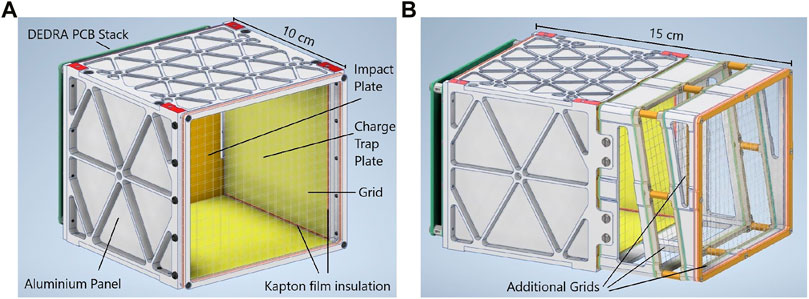
The scientific payload selected for the MOVE-III mission is the DEDRA sensor. The sensor is based on the Munich Dust Counter (Münzenmayer et al., 1993; Konigsmann et al., 1994; Sasaki et al., 2001, 2002), which was developed by the Technical University of Munich in the early 90s. It is designed to quantify the mass and speed of incoming particles, utilising the principle of impact ionization, as described in Section 2.3.1. The sensor consists of a particle trapping box, an analogue electronics front-end module, and a digital front-end module. In total, three sensors facing the flight direction are planned to be hosted on the satellite bus, with two of them planned to be constructed based on the baseline design (Figure 1A), and the third one based on an advanced design developed for the MOVE-III mission (Figure 1B). As the two baseline sensors occupy 1 U each and the advanced sensor 1.5 U, a maximum of three sensors can be hosted on the satellite bus. The advanced design concept aims to obtain directionality readings for the impactors, with the introduction of an additional pair of tilted grids as described in Section 2.3.3. While directional distributions may be derived from measurements of the baseline design sensor (Iglseder et al., 1993), in order to get a measurement of the impact direction of a single particle, the advanced sensor will be employed. Calibration of the sensors is planned for the near future, using a particle accelerator facility. The power budget for all three sensors is 4 W, and the effective surface area is approximately 82 cm2 for each one of the sensors.
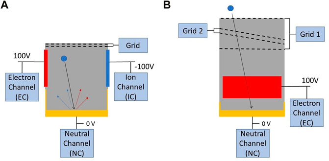
FIGURE 1. Schematic drawing of the DEDRA baseline (A) and advanced (B) design, with the view of the advanced design rotated by 90° with respect to the baseline. The red and blue rectangles represent the Charge Trap Plates (CTPs) for the Electron and Ion Channel respectively. The collector for the Neutral Channel is illustrated in yellow. The grids are connected to the common satellite ground. The ejecta from the impact of a particle are represented as coloured arrows (red: positive charge, blue: negative charge).
2.3.1 Operation principle and sensor calibration
Particles entering the sensor will collide with a surface inside the sensor’s trapping box. After the collision, and depending on the impact velocity, a part of the particle turns into plasma composed of positive ions and negative electrons. Above 5 km/s of impact velocity, a substantial amount of the particle mass turns into a plasma cloud (Münzenmayer, 1995). The resulting ion and electron clouds are trapped at two Charge Trap Plates (CTPs), with one having a high positive (
Signals from the four channels are plotted as charge curves, as shown qualitatively Figure 2. The shape of the curves on the different channels can vary based on the path and impact location of the particle. The difference between the amount of charge detected at the channels after an impact, as well as the time delay between the detections on the channels provide information on the impact location of the particle. In order to derive the velocity and mass of particle that has collided with the sensor box the following empirical equations can be used (Senger, 2006):
where t is the rise time until maximum charge, dt the time delay between charge gain of Ion Channel (IC) and Electron Channel (EC), Q1 the primary charge, Q2 the secondary charge and Q the maximum charge of the channel. The constants (
The mass estimation will be done per channel, based on the channel-specific recorded charge, and an average mass value will be calculated.
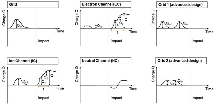
FIGURE 2. Schematic drawing of the measurement curve signals, including the example curves for the two additional grids of the advanced sensor (Grid 1, Grid 2). Qinf corresponds to the charge from electrostatic induction, Q1 and Q2 to the primary and secondary charge and Q to the maximum charge of the channel.
The sensor’s measurement range is limited towards low particle mass and low impact speed by a predefined noise trigger threshold and towards high particle mass and high impact speed by the saturation of the detector electronics (Senger, 2006). The targeted lowest mass threshold corresponds to the minimum particle mass of the current population files of MASTER (10–15 kg), while the upper threshold is expected to be at the order of (10–10 kg) for average impact speeds of 10 km/s in LEO (Münzenmayer et al., 1993; Sasaki et al., 2002). Taking into account that particles may impact from various angles, and considering that impacts from meteoroids are expected to be characterised by high average velocities (ESA, 2015b), the sensor should be able to measure impact speeds within the range of 7–30 km/s. Both lower and upper mass thresholds, as well as their relation to the impact speed shall be defined in detail following the processing of the results of the upcoming calibration campaign. The targeted measurement ranges are well within the capability limits of the sensor, as already demonstrated during the past MDC sensor calibration and operation experiments (Sasaki et al., 2002).
Calibration is planned to be performed using an electrostatic particle accelerator (Mocker et al., 2019). During the experiment, particles of known mass and speed will be shot onto different positions of the sensor box and the impact signals will be recorded. All collected signals will be qualified and classified, with the objective of determining the rise time and amplitude of each signal and subsequently, deriving the particle mass and impact speed (Senger, 2006). The scope of the calibration is the accurate determination of the calibration constants but also the quantification of the expected noise level on-ground which shall further help differentiating actual impacts from noise signal when the detector operates in space. The measurement uncertainties will additionally be quantified following the analysis of the calibration results. Based on the performance of the MDC on Nozomi, maximum error factors of 1.5 and 5 are expected for the speed and mass measurements, respectively (Sasaki et al., 2002).
2.3.2 Baseline architecture
The baseline architecture of the sensor is depicted in Figure 3. The mass of each baseline sensor is 480 g. The sensor’s grids consists of two wires with a diameter of 0.1 mm, with one wire forming the horizontal grid lines and one the vertical on the same plane. The spacing between the grid lines is 4 mm. The wires will be held in place by an aluminium frame. The ±100 V at the CTPs is generated by the Front End Electronics Analog High Voltage (FEEAHV) based on a buck boost converter. At each measurement channel the signal is processed by the Front End Electronics Analog Circuitry (FEEAC). First the incoming signal is amplified by a charge sensitive amplifier. Afterwards the is compressed by a logarithmic amplifier and converted to digital by an analogue-to-digital converter. This conversion takes place at five mega samples per second and a bit depth of ten. This approach results in 500 sample points during a 100 μs period of signal of interest. The digital output is handled by Front End Electronics Digital (FEED). The incoming digital data is continuously buffered for the last 325 μs. The signal is constantly evaluated by the digital trigger logic to check whether an impact has occurred or not. If the signal is larger than a certain threshold with a big enough slope the trigger logic rules an impact has occurred. The specific values will be defined after the calibration campaign. After an impact has been detected, the data will be saved for 325 μs before and after impact detection for each channel of the corresponding sensor. If no impact occurred, the old entries in the buffer are wiped. Together with the sensor number, attitude, position and time information, the impact data is stored as a science data package and sent to the Command and Data Handling (CDH) data storage via the Controller Area Network (CAN)-bus. Finally, the package will be transmitted to the ground station via the Communications (COM) module.
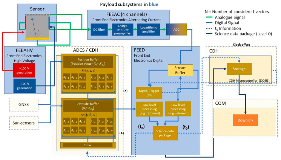
FIGURE 3. Schematic drawing of the overall system architecture of the DEDRA sensor and its interaction with the satellite subsystems, including signal and data streams.
2.3.3 Advanced design
The advanced design sensor shall be capable of measuring mass, velocity and impact direction of the particle. The concept involves the addition of two extra tilted grids, identical in design with the grids of the baseline design, placed in between two parallel ones as seen in Figure 1. In order to accommodate the extra grids, the advanced design sensor is roughly 50% longer than the baseline design sensor and has a mass of 601 g. The tilted grid is rotated by an angle of ϵ = 15° around the axis perpendicular to the CTPs.
The advanced design sensor concept takes advantage of the ability of the grids to record signals when a particle passes through them. Particles in space carry a small electrical charge, which will result in a charge on the grids due to electric induction. By recording the epochs at which the particle passes through the grids, the Cartesian velocity vector (vx, vy, vz) of the particle can be calculated using the equations of motion. The components of the Cartesian velocity vector can be derived as shown in Eq. 3:
where ti is the time at which the particle is inside grid i, hi the height of the grid i with respect to the impact plate (for the tilted grid the higher side is used) and ϵ tilted grid angle.
From the velocity vector, the angles of incidence θ and ϕ can then be derived as shown in Eq. 4. Due to the fact that vy is ambiguous there are two possible solutions for ϕ. The ambiguity, which comes from the fact that vy is derived from the absolute velocity v and the components vx and vz, can be resolved by utilising the charge differences recorded on the right and left CTPs.
2.4 Data products
Measurement data acquired by active in-situ detectors often require on-orbit and/or on-ground processing in order to eliminate measurement noise and derive meaningful quantities that can be used for further applications (Oikonomidou et al., 2021). For the DEDRA sensors, which operate on the principle of plasma ionisation, expected noise sources include charged particles in the ionosphere, photo ionization due to solar radiation, electromagnetic fields and noise originating from the satellite electronics. The entrance grids are grounded to the common satellite ground and are expected to provide a first-degree shielding against outer electromagnetic noise, while signals on the neutral channel may additionally help identify false-positive impacts. The characteristics of the signals on the different sensor plates shall be determined during the calibration campaign, and shall provide the baseline for comparison with the recorded impacts.
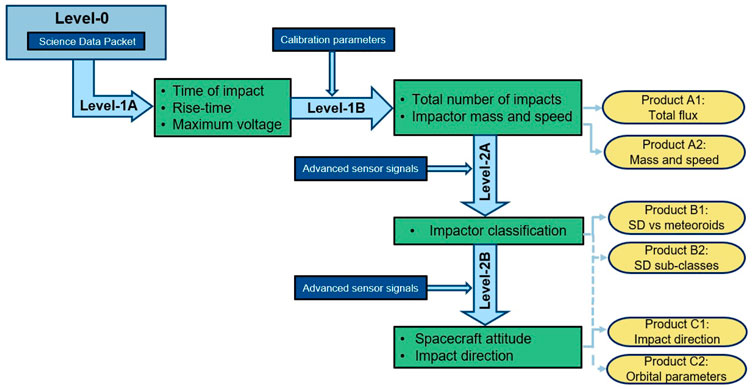
In order to provide products that can easily be incorporated in the small particle validation process, a data processing chain which will generate four possible products is suggested. The chain consists of five different processing steps, starting with Level-0 and up to Level-2B. Six data products are expected to be generated, with products A1 and A2 being the main deliverables and products B1 to C2 being experimental products whose generation will depend on the performance of the advanced design sensor (Figure 4).
• Level-0: it refers to all processing done on board and produces the science data packet (as described in 2.3.2) which is downlinked from the satellite.
• Level-1A: with input the science data packet, it provides the time of impact, the signal rise time and the maximum voltage.
• Level-1B: with input the products of Level-1A, it produces the first of the deliverables i.e., is the total number of objects detected by the sensors during the mission lifetime, as well as the mass and speed of the detected particles. The mass and the speed of the particles will be estimated through empirical relations as defined in Iglseder (1986), Senger (2006), Münzenmayer et al. (1993) and the calibration parameters which will be derived during the on-ground calibration campaign.
• Level-2A: it aims at using the advanced sensor directionality data (impact angles) and the current knowledge on the space debris and meteoroid environment in order to classify the data into space debris or meteoroid impacts. The classification will be performed on the basis that space debris particles are most likely to impact the sensor head-on, while meteoroids are expected to impact with broader angles and significantly higher velocities. Classification between the different space debris classes will also be investigated.
• Level-2B: it aims at using the advanced design sensor data in order to derive the direction from which a particle impacted the sensor. Depending on the performance of the advanced sensor and the accuracy of the measurements, an orbit integration for the determination of the orbital parameters of the impactor can be performed.
2.5 Expected space debris and meteoroid flux
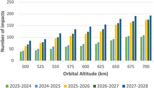
The space debris and meteoroid flux which is likely to be encountered during the lifetime of MOVE-III has been estimated using ESA’s space debris and meteoroid MASTER-8.0.3 model. All simulations were run for the period of 1 year, which corresponds to the nominal lifetime of the mission. The simulation years cover the timespan between 2023 and 2028, as MOVE-III is expected to be launched within the next couple of years. In order to get a better picture of the space debris environment in the near-orbital regime that is targeted, altitudes between 500 and 700 km were studied. The impactors considered by MASTER are all space debris objects and meteoroids that belong in the expected sensor’s trackable mass range (10–15 kg to 10–10 kg). Assuming aluminium density and spherical impactors, the trackable mass range corresponds to objects with an approximate diameter between 1 and 40 μm. MASTER’s condensed population files were used for the modelling of the space debris objects while the Grün model with a Taylor velocity distribution is employed for the modelling of the meteoroids (Oikonomidou et al., 2021). The resulting flux to the oriented surface has been scaled based on the effective detection area of the three sensors.
The evolution of the total number of impacts is characterized by an increasing trend over increasing altitude, reflecting the evolution of the space debris environment in LEO (Figure 5). The lowest flux is predicted for the years 2023–2024 and 500 km (39 impacts on 3 sensors), while the highest flux is predicted for the years 2027–2028 and 700 km (193 impacts on 3 sensors). The individual contribution of the meteoroid and space debris population has also been simulated individually (Figure 6), illustrating that the steadily increasing pattern is a characteristic of the space debris flux. The meteoroid flux, which describes the background population with an inherent averaging of seasonal streams (ESA, 2015b), follows a more constant distribution pattern, nevertheless seeing a slight increase with increasing orbital altitudes. An interesting aspect of the space debris flux increase concerns the year 2025, when a significant increase in the flux in all altitudes can be observed. In order to better understand the increase in the space debris flux, the different contributing sources were modelled individually using MASTER.

FIGURE 6. Evolution of meteoroid (A) and space debris (B) flux: number of impacts on 3 sensors per year.
MASTER supports all known debris sources and their evolution in time. In addition to the past launch traffic which is considered by the Launch-Mission-Related Object (LMRO) population, MASTER further includes the following sources: on-orbit fragmentations (explosions and collisions), solid rocket motor firings (SRM slag and dust), coolant release from nuclear reactors in space (NaK droplets), surface degradation and/or delamination (paint flakes and multi-layer insulation particles) and ejecta due to impacts of small particles (ESA, 2015b). According to the size distribution of the objects from the aforementioned sources and the targeted orbital altitude, MOVE-III is expected to mainly encounter particles originating from SRM firings, ejecta, paint flakes and possible explosion/collision fragments. Indeed, the results of the simulations show that the biggest contributors to the space debris flux are ejecta and SRM dust (Figure 7), with the remarkable change in flux in 2025 coming mostly from a rapid increase in the SRM dust population and a more stable increase in the ejecta population. The general increase in the ejecta and SRM objects is likely to be related to the solar activity, as the next predicted solar maximum considered by MASTER takes place between 2024 and 2025. Starting 2025, the solar flux is predicted to start moving towards its next solar minimum, indicating that the orbital lifetime of the particles is expected to be increased, leading to a higher accumulation of objects in orbit. The increasing trend in the ejecta graph may additionally likely to be related to a predicted increase in the LMRO population, which is taken into account for the generation of the ejecta population (ESA, 2015b). For the case SRM dust, its flux may also be sensitive to individual firings that could be affecting the estimates during certain years (e.g., 2025–2026).
The flux estimates have been taken into account in order to decide the optimal operational orbit of MOVE-III. While higher orbital altitudes are characterised by higher flux, compliance with the space debris mitigation guidelines related to de-orbiting in LEO also needs to be considered. Following a trade-off analysis between high flux and de-orbiting time (as described in Section 4.1), MOVE-III is expected to fly between 500 and 600 km and collect an average of 100 space debris and meteoroid impacts within 1 year of operations. It should additionally be mentioned that for 100 true impacts within a year, and under the assumption that the expected number of impacts follow a Poisson distribution, the contribution of the dataset to MASTER would be 100
3 System architecture
In order to ensure a successful MOVE-III mission, the various subsystems, both on ground as well as in space, have to work together as one coherent system. This section describes the current status of the bus development, featuring the platform architecture as well as the main subsystems and their interactions.
3.1 Platform architecture
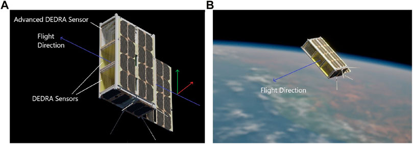
The current state of the satellite configuration is depicted in Figure 8. The Printed Circuit Board (PCB) stack with the boards (from left to right) of the Communications (COM), Command and Data Handling (CDH), and Attitude Determination and Control System (ADCS) subsystems as well as the payload interface-board and the two battery boards can be seen, coloured in blue, inserted into the central backplane. Adjacent to the PCB stack the ADCS compartment is located, consisting of reaction wheels and magnetorquers. The unit containing the batteries is completed by the payload PCB stack. The three DEDRA sensors are located on the backside, and will all point towards the flight direction during normal operations. Opposite to them is the deployable flap panel, which houses additional solar cells, as well as the antennas.
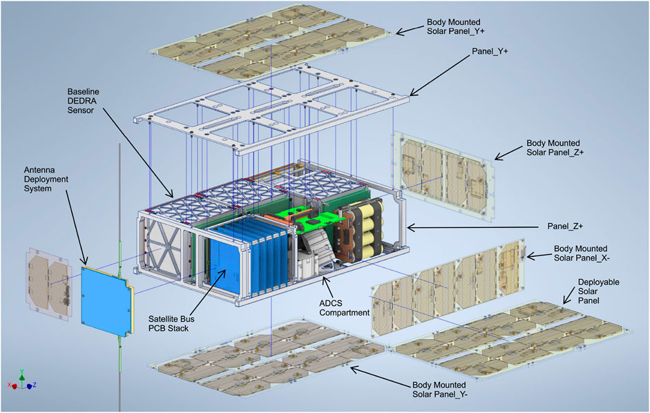
FIGURE 8. Explosion drawing of the space segment of MOVE-III. Note that all DEDRA sensors point in the same direction, as well as the deployable flap panel. Flight direction is +X.
The Munich Orbital Verification Experiment (MOVE) satellite is based on the multi-mission satellite platform MOVE-BEYOND, which is being developed concurrently by the same team. The underlying satellite platform is designed in such a way that it is able to supply the payload with all required functionalities and resources, such as power, data storage and communications. The bus is comprised of independent standardized boards on which a microcontroller and subsystem-specific components are hosted. A backplane connects all subsystems, provides power and the central communication’s CAN bus. It is noted that every subsystem is housed on at least one dedicated PCB.
All microcontrollers run on the in-house developed OS Distributed Operating System Initiative for Satellites (DOSIS), which provides a real time operating system and a message based communication over the CAN bus (Rückerl et al., 2021). The modular nature of the system allows the design teams to iterate and verify their designs independently from one another. An overview of the MOVE-III space segment architecture can be seen in Figure 9. The ground segment is made up of the Chair of Astronautics (LRT)’s ground station and Mission Control Centre which houses the Operations (OPS) infrastructure, used by the Mission Control (MC) team to handle the produced data as well as to command the satellite. Communication between ground and space segment is realised via the COM subsystem. Commands are sent to the CDH unit, which controls the state of the satellite, saves all generated data and executes commands. For MC to have access to the latest telemetry, it is saved in a ring-buffer. In addition, it provides time synchronization to all subsystems and Global Navigation Satellite System (GNSS) data for payload measurements. In order to create a complete data package, the payload also needs attitude information, which is provided by the ADCS system with the help of its Sun sensors and Inertial Measurement Unit (IMU) data. The ADCS is also responsible for attitude control through both magnetorquers (air coils) and reaction wheels, ensuring that the DEDRA sensors are pointed in flight direction and the solar cells on the deployable flap panel are aligned for maximum power generation. Finally, the Electrical Power System (EPS) regulates the power generated by the solar cells to provide power to the satellite bus and control the charging process of the Lithium-ion (Li-ion) batteries. Furthermore, the EPS provides safety features such as an Undervoltage Protection as well as active power monitoring. Every subsystem may be switched off, either on command or automatically, in case of a detected anomaly.
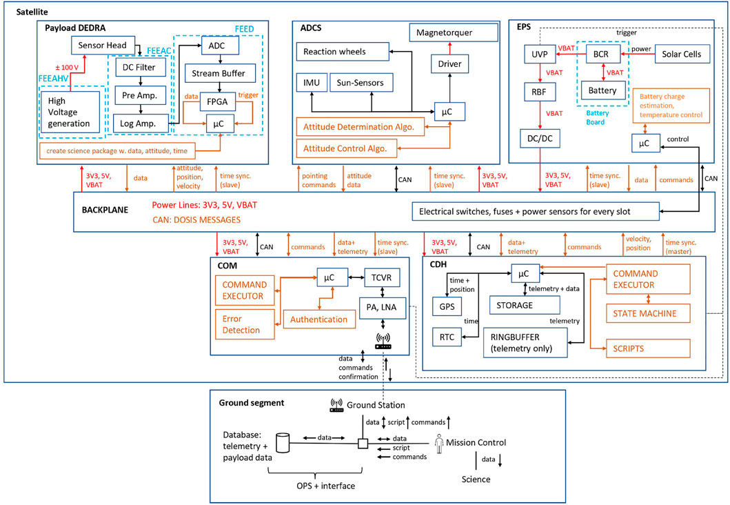
FIGURE 9. Overview of the system. Power connections are drawn in red, data connections are drawn in orange, hardware blocks are black and logical blocks are orange. If a subsystem consists of more than one PCB, it is indicated by dotted blue lines.
As the project has recently passed the Preliminary Design Review (PDR), the next step will be the finalisation of the brass model design and the construction of a first prototype model. The Critical Design Review (CDR) is planned for 2023, and the Engineering Model will be assembled after the completion of the review. A functional testing and qualification campaign will follow, after which the flight model will be manufactured.
Running verification of the platform design is achieved via stratospheric balloon missions, wherein prototypes of the system are sent to a height of 35 km to test their reliability under stress conditions, particularly the communications and power systems. A hardware-in-the-loop version of the backplane and subsystem boards is used to continually test for errors during the design process. An in-house Thermal Vacuum Chamber (TVAC) provides a testing environment for thermal model correlation and functional testing.
3.2 Subsystem overview
The following paragraphs give a short overview of the solutions and the adaptations made to the subsystems for the MOVE-III mission. With the exception of the reaction wheels, Sun sensors and communications module, the subsystem hardware is developed internally by the MOVE team.
3.2.1 Attitude determination and control system
The ADCS controls the satellite’s attitude as commanded by CDH and is responsible for the orientation of the DEDRA sensors and the solar array and for maintaining a stable down-link to the ground station. Its tasks also include detumbling the satellite after deployment, fulfilling the attitude requirements of the payload sensors and providing information about the attitude to the payload. To determine the satellite’s attitude, six side-panel mounted third-party Sun sensors are used to calculate the Sun vector. An Inertial Measurement Unit (IMU) provides data on the magnetic field as well as on the angular velocity. The measurement values are processed with position data (either from Two-Line Element Set (TLE) orbit calculations or GNSS) and a magnetic field model of the Earth in an extended Kalman filter to determine the attitude. With the attitude information, the actuators can be controlled. In order to detumble the satellite, three in-house developed magnetorquers are used, which are controlled by a B-Dot controller with help of the magnetic field sensor. For Sun pointing, the information from the Sun sensors and the angular velocity is processed. To point the satellite within the limits determined by the payload in the flight direction, four reaction wheels are used. The reaction wheels will be purchased. The Quaternion PID controller is fed with all attitude information and returns commands for the reaction wheels as well as the magnetorquers, which are used for momentum dumping. With this setup a prograde pointing accuracy of less than 5° is achieved, while being able to determine the attitude with an error of less than 1°.
3.2.2 Command and data handling
The CDH system provides MC with the ability to send commands to subsystems and manages the collection, storage and retrieval of telemetry and payload data. It also manages the overall state of the satellite, provides the ability to upgrade the firmware of subsystems and allows for autonomous operation. The storage will be implemented with a space-grade MRAM chip, allowing to store between 2 and 4 weeks of telemetry and over 1 year of payload data. Due to implementation choices, CDH will also provide the GNSS time, position, velocity and precision to the ADCS and Payload (PL) subsystem. For this, a commercial off the shelf GNSS module with unlocked firmware will be used. The GNSS, telemetry collection and retrieval have been implemented and tested.
3.2.3 Communications
The COM subsystem provides communication between the satellite subsystems and the MC. A transceiver (TCVR) operates in the UHF band and provides a low data rate radio link of up to 250 Kbps for telemetry and commanding failure conditions. The COM forwards all CAN messages addressed to the MC using the radio link, while the incoming radio messages are put on the CAN bus. In this process, the COM will not make any changes in the message payload which is a complete DOSIS message. For the uplink a low noise amplifier is used in connection with the TCVR, while the downlink operates with a power amplifier. The system is controlled by a micro controller, which further handles tasks such as authorization, error detection and layer handling. To reset the satellite on command from MC the COM system has a direct connection to the EPS system. This is necessary in case of a COM failure, so that an automatic watchdog may reset the system. The primary COM module will be purchased from a third party provider.
3.2.4 Electrical power system
The function of the Electrical Power System (EPS) is to provide power to all subsystems and facilitate communication between them. It consists of the backplane, which hosts battery and subsystem PCBs on evenly spaced slots, and the EPS microcontroller. The backplane converts the solar power into stable 3.3 V and 5 V lines and an unregulated battery voltage line. It also facilitates communication between subsystems through the CAN bus, connected to every slot and the EPS microcontroller. This controller monitors the power path and can switch off any slot during an undervoltage or overcurrent event. An Undervoltage Protection (UVP) circuit cuts off the bus from power should the batteries be discharged to an undesirable level. The EPS can use the UVP to hard-reset the entire bus in case of a COM or CDH failure. The EPS is scalable in blocks. The backplane may be expanded to up to fourteen slots. If increased power capacity is necessary, another battery board containing four Li-ion batteries with a capacity of 20.8 Wh may be slotted into the backplane, and generation capacity increased by adding another solar array and controller. The EPS provides two battery boards yielding 41.6 Wh. This design choice allows the EPS to satisfy power requirements for different missions. The platform provides a range of constellations for the boards that belong to the EPS and gives flexibility when handling the power budget of the satellite. Especially concerning the payload this approach is valuable as the DEDRA sensors will consume a significant portion of the power available because of the technical realisation of high voltage differentials to detect particles. An additional challenge is keeping the sensors pointed in the flight direction. Due to this, the satellite is restricted in its freedom to point its solar panels into the Sun. This necessitates a very flexible EPS concept in order to accommodate multiple possible orbits and thus panel layouts and numbers. The EPS achieves this through its expandable nature, which allows for varying amounts of panels and controllers.
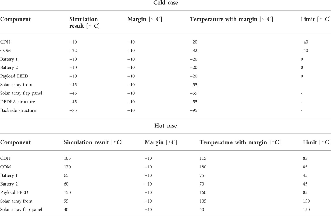
For the current configuration of the solar panels (Figure 8) there are orbits in which power generation is less than what would be required to sustain scientific operation through the entire orbit duration. Especially orbits with a low beta angle between solar vector and orbital plane are a concern. This may be mitigated by adjusting the angle of the deployable solar panel, although the final design of the deployable structures must be put on hold until the final orbit is decided. Due to thermal considerations, the battery temperature may fall below or exceed acceptable levels (Table 1), which shortens battery life and risks battery failure. While active battery heating mitigates low temperatures, high temperatures require a bus shutdown to safeguard the batteries. Additional time in the Sun tends to raise the temperature of the bus at the same time as providing more power. Therefore, a trade-off between power generation and conserving acceptable temperature levels is required, which shall be finalised once the launch provider, final orbit and launch date have been decided.
3.2.5 Mechanical structure
The mechanical structure’s main purpose is to house all other subsystems and ensure their survival during the launch and the projected mission duration. The form factor of this mission is chosen to be 6U, which implies maximum dimensions of 366 × 226.3 × 100 mm3 according to the CubeSat Design Specification (Cubesat.org, 2020). Materials used to build the structure are aluminium for the frame and composites like carbon fibre reinforced plastic for deployables and parts of the sensors. Titanium will be used for screws in the deployment mechanism. 3.5 U of the inner volume will house the DEDRA sensors, whose main structure will also be built with aluminium plates. The structural design, as shown in Figure 10, is mainly driven by the detector payload design. MOVE-III will employ two baseline sensors and one advanced. The survival of the sensors during launch and deployment is one of the top priorities for the Structure subsystem. The DEDRA sensors act as part of the structure to support the outer panels in order to maximise the sensor’s aperture but also keep its structural rigidity. The advanced sensor includes an additional grid assembly which is stacked together using standoffs and CNC-milled aluminium pieces (Figure 11).
3.2.6 Thermal
The Thermal subsystem simulates expected temperatures on orbit and provides measures to keep all components in their operating or storage temperature ranges. The software ESATAN-TMS is used to model the satellite. The simulation considers a LEO with an altitude of 530 km, eccentricity 0.001, inclination 97.52°, right ascension of the ascending node 100.56°, argument of perigee 80°, and mean anomaly 180°. In the cold case the satellite tumbles randomly in space while no internal power is dissipated, in the hot case the all systems are operating at their peak power consumption level while the satellite points in the flight direction and the solar panels are turned towards the Sun. The results for the cold and hot case can be seen in Table 1. As the minimum and maximum temperature limits are exceeded the first proposed thermal measure is coating all surface on the inside of the satellite with black paint such that the radiative heat exchange between the components is improved. To heat the batteries additional battery heaters are used. The effectiveness of this design shall be assessed with further simulations and testing.
4 Debris mitigation plan
In accordance to the Space Debris Mitigation guidelines, all ISO (ISO, 2019) and ESSB (ESA, 2015a) requirements applicable to the MOVE-III mission have been taken into account during the design and development of the satellite bus and the definition of the scientific objective. Based on the identified requirements, a Compliance Matrix has been prepared as part of the Preliminary Design Review (PDR) (MOVE-III, February 2022). In this section we present two important aspects of the Debris Mitigation Plan applicable to the mission: de-orbiting and damage and risk assessment. The damage and risk assessment covers two aspects: 1) survivability analysis of the sensor and bus during the nominal lifetime of the mission and 2) risk assessment for on-orbit break up due to a space debris or meteoroid impact before the mission’s end of life. The respective requirements as well as other supporting studies including re-entry and material survivability and risk from on-board energy sources are included in the PDR.
4.1 Mission lifetime and de-orbiting
Various studies have shown that space debris flux increases at an altitude of 400 km and peaks at around 1,000 km (ESA, 2015b; Cooke et al., 2017). This means that the selection of a high orbital altitude would favour the scientific objective of the mission. However, in order for the mission not to contribute towards the growing amount of space debris in Earth orbits, MOVE-III is designed such that it complies with the international guidelines and standards, which, among others, state that the orbital lifetime of a satellite without collision avoidance capabilities operating in LEO, must not exceed 25 years starting from the orbit injection epoch (ESA, 2015a; ISO, 2019). This is commonly referred to as the “25-year-rule.” MOVE-III falls within this category, as it does not have collision avoidance capabilities. While the use of a de-orbiting device would allow the satellite to orbit in higher altitudes while still being compliant with the 25- year-rule, the concept has been ruled out due to reliability concerns regarding the currently available de-orbiting mechanisms for CubeSats. The accommodation of the device in the platform (a de-orbiting sail system would occupy about 0.5 U which would require reducing the number of sensors by one, decreasing the scientific payload detection capabilities by 1/3), as well as due to budget limitations were defining factors for this decision.
In light of this, the following optimization problem is presented: What is the highest possible 25-year-rule compliant altitude still characterised by high flux in order to ensure successful data collection? To solve for this, the mission scenario was simulated using the ESA’s DRAMA software suite. The analysis was performed in two parts: First, an initial 5-year time span with attitude control and zero tumbling. This corresponds to the early operations, commissioning and nominal operations phases mentioned in Section 2.2, along with a mission extension of 4 years. The second part is a maximum of 20 years decommissioning phase with no attitude control, hence the satellite will experience random tumbling and although the drag cross section is not constant, its value can be replaced with an effective cross section. If and only if the satellite re-enters during this time, the altitude is qualified as compliant.
The drag cross sections were computed with help of the CRoss Section of Complex Bodies (CROC) of the DRAMA suite, which in the case of random tumbling, averages the cross section over different viewpoints (Sanchez-ortiz et al., 2013). The normal cross section has a value of 0.039 m2 and the effective cross section a value of 0.102 m2. At an orbital insertion date of the first of August 2024, the initial values of the orbital elements and other parameters are shown in Table 2. The orbital elements were obtained with help of the Orbit Wizard tool from Systems Tool Kit (STK). The orbital evolution and lifetime assessment was performed with Orbital SpaceCraft Active Removal (OSCAR). In order to combine the two parts of the simulation, the final parameters of the first simulation (5 years, normal cross section) were taken as the starting parameters of the second simulation (max. 20 years, effective cross section). This was performed for 2 different mass setups, 6.5 kg and 7.0 kg, and for different initial altitudes between 540 and 650 km. The OSCAR simulation results are detailed in Table 3. For both mass setups, at any altitude at or below 600 km the orbit is compliant, with a fair margin of error, and provides an appropriate altitude for the scientific purpose of the mission, in agreement with the analysis performed in Section 2.5. Therefore, the satellite’s altitude shall not exceed 600 km. The results were additionally cross-checked with the help of the software Semi-analytic Tool for End of Life Analysis (STELA) from CNES and Debris Assessment Software (DAS) from NASA.
4.2 Risk assessment
4.2.1 Damage assessment
The risk of the satellite and sensors being damaged by trackable or untrackable objects during the extended operational mission lifetime (5 years) has been assessed using the MASTER-based Impact Flux and Damage Assessment (MIDAS) tool of the DRAMA 3.1.0 software suite. The damage assessment was performed for 575 km, with the objective of studying the probability of penetration for all exterior surfaces of the satellite exposed to the space environment (including the PCBs and the solar arrays). As the surfaces of satellite are mostly made up of glass fibre with a density of 2.5 g/cm3 and a thickness of 1.5 cm (2 cm for the solar panel), a single wall Ballistic Limit Equation (BLE) (Cour-Palais Thin Plate) was employed for the analysis. Similarly, a single-wall BLE is also employed for the leading face surface, which corresponds to the inside of the sensor boxes made mainly of aluminium, with a density of 2.7 g/cm3 and a thickness of 0.5 cm.
The results of the analysis show that the probability of impact with an object in the mass range 10–15 and 10–10 kg within a year is at 100%, but decreases significantly for particles with masses around 10–8 kg. The biggest risk of penetration (for all surfaces) is posed by particles with masses between 10–5 kg and 10–3 kg. However, the risk is deemed very low at all cases, as the probability of a particle penetrating any of the exposed surfaces during the extended operational lifetimes does not exceed 0.61 ⋅ 10–3 (leading surface, Figure 12). The combined probability of no penetration for all studied surfaces equals 99.93%, which is considered acceptable when compared against commonly used survivability requirement thresholds (e.g., 90% as per ESA (2022c), ISO (2019)).
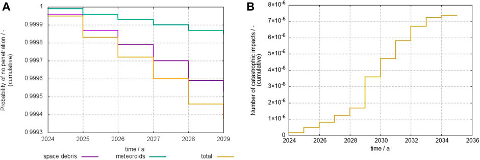
FIGURE 12. Probability of no penetration vs. time for the leading face during the extended lifetime (A) and cumulative number of catastrophic impacts during the complete mission lifetime (B) at an orbital altitude of 575 km.
4.2.2 Break-up risk assessment
The probability of the MOVE-III CubeSat breaking up before its end of life due to a space debris or meteoroid impact has additionally been assessed using the MIDAS tool of the DRAMA suite. Similar to Section 4.1, we assume a normal cross section for the first 5 years in orbit and an effective cross section for the remaining years until re-entry. As the population files of MASTER currently only support simulations until 2036, the case of a launch in 2024, with an initial altitude of 575 km was examined. The flux of both, trackable and untrackable objects, was (simultaneously) analyzed for objects with diameters between 10–6 and 100 m. For the MIDAS tool, all objects with a diameter
The catastrophic flux for the first 5 years of the mission has been estimated to be 1.96 ⋅ 10–6, while the catastrophic flux for the remaining years equals 5.42 ⋅ 10–6 (Figure 12). The total probability of a break-up before the mission’s end of life can be calculated with the help of Poisson statistics (ESA, 2022c):
where N is the number of impacts during the mission life and Pcat is the probability of catastrophic impact. This yields a value of 7.38 ⋅ 10–6, which is below the currently recommended thresholds for LEO orbits [e.g., 10–4 in ESA (2022c), Schaus et al. (2021)].
5 Conclusion
The work describes the current stage of developments of the MOVE-III CubeSat project at the Technical University of Munich, and discusses its scientific objective i.e., the acquisition of in-situ measurements of sub-millimetre space debris and meteoroids in LEO, with the objective of creating a dataset of flux, particle mass, and particle velocity that can support the validation of space debris models and space environment characterisation studies. The payload of MOVE-III, which consists of three plasma ionization sensors, as well as its operation principle and the expected data products are presented. An advanced sensor design, which can provide particle direction measurements using additional grids, is proposed. The mission is expected to be launched in 2024 at an altitude between 500 and 600 km, which is defined by a trade-off analysis between an altitude with high flux and an altitude which complies with the international guidelines for LEO orbits relevant to the mission disposal. Simulations with ESA’s MASTER model have shown that within 1 year of operations, MOVE-III will collect up to 150 impacts, depending on the operational altitude and the launch year.
The system architecture as well as the satellite bus design of MOVE-III are presented, and the functionalities and interactions of the different subsystems are introduced. In accordance to the relevant space debris and mitigation guidelines, a Debris Mitigation Plan has also been drafted, which, among others, ensures disposal within 25 years, assesses the impact risk for the payload and the satellite platform and evaluates the probability of a break-up due to an impact before the mission’s end of life. With the current mass and launch estimates, MOVE-III can fly up to 600 km, with a remaining lifetime of about 20 years. For altitudes below 600 km, the satellite is also compliant with suggested break-up thresholds, with a 7.38 ⋅ 10–6 probability of catastrophic impact before re-entry.
Data availability statement
The raw data supporting the conclusion of this article will be made available by the authors, without undue reservation.
Author contributions
XO: abstract, introduction, scientific motivation, data products, expected space debris and meteoroid flux, break-up assessment, conclusion, review and editing. EK: abstract, mission timeline, conclusion review and editing. DS: introduction, platform architecture, COM, ADCS, THM, review and editing. FS: system architecture, platform architecture, review and editing. FF: system architecture, subsystem overview, platform architecture, review and editing. JH: subsystems overview, command and data handling, review and editing. AS: de-orbiting and mission lifetime, damage assessment, break-up risk assessment, review and editing. PP: payload. DM: expected space debris and meteoroid flux: simulation, review and editing. TY: damage assessment, break-up risk assessment, de-orbiting and mission lifetime. MV: damage assessment. SW: electrical power system, review and editing. ZZ: mechanical structure.
Acknowledgments
The authors would like to thank all university students and staff involved in the MOVE project. We would also like to express our gratitude to all reviewers that took part in the System Definition and Preliminary Design Review and provided us with invaluable feedback.
Conflict of interest
The authors declare that the research was conducted in the absence of any commercial or financial relationships that could be construed as a potential conflict of interest.
Publisher’s note
All claims expressed in this article are solely those of the authors and do not necessarily represent those of their affiliated organizations, or those of the publisher, the editors and the reviewers. Any product that may be evaluated in this article, or claim that may be made by its manufacturer, is not guaranteed or endorsed by the publisher.
References
Braun, V., Clormann, M., Oikonomidou, X., Lemmens, S., and Sanvido, S. (2021). “Fostering collaborative concepts in space debris mitigation,” in 8th European conference on space debris, ESA/ESOC.
Cooke, W., Matney, M., Moorhead, A. V., and Vavrin, A. (2017). “A comparison of damaging meteoroid and orbital debris fluxes in Earth orbit,” in 7th European conference on space debris (ESA space debris office).
Drolshagen, G., Svedhem, H., and Grün, E. (2001). Measurements of cosmic dust and micro-debris with the gorid impact detector in geo. Space Debris 473, 177–184.
ESA (2022a) DISCOSweb. Available at: https://discosweb.esoc.esa.int/.
ESA (2022b). Esa fragmentation blog. Available at: https://fragmentation.esoc.esa.int/.
ESA (2015b). MASTER-8 final report: Enhancement of S/C fragmentation and environment evolution models.
ESA (2022c). Small debris and meteoroid risk requirements verification guidelines based on DRAMA/MIDAS. Space Debris Off.
ESA (2022d). Space environment statistics. Available at: https://sdup.esoc.esa.int/discosweb/statistics/.
Horstmann, A., Manis, A., Braun, V., Matney, M., Vavrin, A., Gates, D., et al. (2021). in 8th European conference on space debris (ESA space debris office).Flux comparison of master-8 and ordem 3.1 modelled space debris population.
Iglseder, H., Grün, E., Münzenmayer, R., and Svedhem, H. (1993). “Analysis of the results of the two-year operations of the Munich dust counter - a cosmic dust experiment on board the satellite hiten,” in Proceedings of the international astronomical symposium.
Iglseder, H. (1986). Ladungsemission beim hochgeschwindigkeitseinschlag. Munich, Germany: Dissertation, Lehrstuhl für Raumfahrttechnik, Technische Universität München.
Krag, H., Serrano, M., Braun, V., Kuchynka, P., Catania, M., Siminski, J., et al. (2017). A 1 cm space debris impact onto the sentinel-1a solar array. Acta Astronaut. 137, 434–443. doi:10.1016/j.actaastro.2017.05.010
Kuitunen, J., Drolshagen, G., McDonnell, J., Svedhem, H., Leese, M., Mannermaa, H., et al. (2001). Debie-first standard in-situ debris monitoring instrument. Darmstadt, Germany: EUROPEAN SPACE AGENCY-PUBLICATIONS-ESA SP 473, 185–190.
McKnight, D. S., and Hoyle, S. (1992). “Investigation of ANOVA techniques applied to breakup modeling,” in 18th International Symposium on Space Technology and Science.
Menicucci, A., Drolshagen, G., Kuitunen, J., Butenko, Y., and Mooney, C. (2013). In-flight and post-flight impact data analysis from DEBIE2 (debris-in-orbit-evaluator) on board of ISS. Proc. 6th Eur. Conf. Sp. Debris., 2–5.
Mocker, A., Albin, T., Gruen, E., Simolka, J., Stier, A., Strack, H., et al. (2019). “The hyper-velocity dust research laboratory at the institute for space systems at the University of stuttgart,” in EPSC-DPS joint meeting 2019.
Münzenmayer, R. (1995). Beiträge zur experimentellen Erforschung des Staubes im Weltall. München: Utz.
Münzenmayer, R., Iglseder, H., and Svedhem, H. (1993). The Munich Dust Counter MDC - an experiment for the measurement of micrometeoroids and space debris. Space Debris, 117–123.
Oikonomidou, X., Braun, V., Pail, R., Gruber, T., Schummer, F., Meßmann, D., et al. (2021). “MOVE-III - an in-situ detector to support space debris model validation,” in 8th European conference on space debris (Darmstadt, Germany: ESA Space Debris Office).
Rückerl, S., Ukkola, M., Würl, S., and Faehling, M. (2021). Distributed computing for modular reliable nanosatellites. IEEE Aerosp. Conf. doi:10.1109/AERO50100.2021.9438474
Sanchez-ortiz, N., Dominguez-gonzalez, R., Correira De Oliveira, J., Gelhaus, J., Kebschull, C., and Krag, H. (2013). “Computation of cross section of complex bodies in esa drama tool,” in 6th European conference on space debris (Darmstadt, Germany: ESA/ESOC).
Sasaki, S., Igenbergs, E., Ohashi, H., Hofschuster, G., Münzenmayer, R., Naumann, W., et al. (2001). Interplanetary dust observations in the earth-mars region by mars dust counter (MDC) on board NOZOMI: Three-year results. Meteoroids 2001 Conf. 495, 595–599.
Sasaki, S., Igenbergs, E., Ohashi, H., Münzenmayer, R., Naumann, W., Hofschuster, G., et al. (2002). Observation of interplanetary and interstellar dust particles by Mars dust counter (mdc) on board nozomi. Adv. Space Res. 29 (8), 1145–1153. doi:10.1016/s0273-1177(02)00130-8
Schaus, V., Letizia, F., Virgili, B. B., and Lemmens, S. (2021). “Leveraging space debris simulation results: Revisiting guideline values for explosion and cumulative collision rate,” in 8th European conference on space debris, ESA/ESOC.
Senger, R. (2006). Data Handling and Evaluation for Autonomous Experiments in Interplanetary Missions (Dissertation, Lehrstuhl für Raumfahrttechnik, Technische Universität München).
Glossary
ADCS Attitude Determination and Control System
ARES Assessment of Risk Event Statistics
BLE Ballistic Limit Equation
CAN Controller Area Network
CDH Command and Data Handling
CDS CubeSat Design Specifications
COM Communications
CROC CRoss Section of Complex Bodies
CTP Charge Trap Plate
DEDRA Debris Density Retrieval and Analysis
DOSIS Distributed Operating System Initiative for Satellites
DRAMA Debris Risk Assessment and Mitigation Analysis
ECSS European Cooperation for Space Standardization
EC Electron Channel
EMR Energy-to-Mass Ratio
EPS Electrical Power System
ESA European Space Agency
FEEAC Front End Electronics Analog Circuitry
FEEAHV Front End Electronics Analog High Voltage
FEED Front End Electronics Digital
FEM Finite Element Method
GEO Geostationary Orbit.
GNSS Global Navigation Satellite System
I2C Inter-Integrated Circuit
IADC Inter-Agency Space Debris Coordination Committee
IMU Inertial Measurement Unit
ISO International Organization for Standardization
IC Ion Channel
LEO Low Earth Orbit
Li-ion Lithium-ion
LRT Chair of Astronautics
MASTER Meteoroid and Space Debris Terrestrial Environment Reference
MC Mission Control
MDC Munich Dust Counter
MOVE Munich Orbital Verification Experiment
MIDAS MASTER-based Impact Flux and Damage Assessment
NASA National Aeronautics and Space Administration
NC Neutral channel
OPS Operations
ORDEM Orbital Debris Engineering Model
OSCAR Orbital SpaceCraft Active Removal
PCB Printed Circuit Board
PL Payload
SSN Space Surveillance Network
SPI Serial Peripheral Interface
SRM Solid Rocket Motor
TCVR Transceiver
THM Thermal Design
TLE Two-Line Element Set
TMTC Telemetry and Telecommand
TUM Technical University of Munich
WARR Scientific Workgroup for Rocketry and Spaceflight
Keywords: space debris, impact detection, CubeSat, MOVE-III, DEDRA, space debris modelling
Citation: Oikonomidou X, Karagiannis E, Still D, Strasser F, Firmbach FS, Hettwer J, Schweinfurth AG, Pucknus P, Menekay D, You T, Vovk M, Weber S and Zhu Z (2022) MOVE-III: A CubeSat for the detection of sub-millimetre space debris and meteoroids in Low Earth Orbit. Front. Space Technol. 3:933988. doi: 10.3389/frspt.2022.933988
Received: 01 May 2022; Accepted: 16 September 2022;
Published: 17 October 2022.
Edited by:
Vitali Braun, IMS Space Consultancy, GermanyReviewed by:
Noah Ledford, Fraunhofer Institute for High-Speed Dynamics (FHG), GermanyGerhard Drolshagen, University of Oldenburg, Germany
Copyright © 2022 Oikonomidou, Karagiannis, Still, Strasser, Firmbach, Hettwer, Schweinfurth, Pucknus, Menekay, You, Vovk, Weber and Zhu. This is an open-access article distributed under the terms of the Creative Commons Attribution License (CC BY). The use, distribution or reproduction in other forums is permitted, provided the original author(s) and the copyright owner(s) are credited and that the original publication in this journal is cited, in accordance with accepted academic practice. No use, distribution or reproduction is permitted which does not comply with these terms.
*Correspondence: Xanthi Oikonomidou, eGFudGhpLm9pa29ub21pZG91QHR1bS5kZQ==; Eleftherios Karagiannis, bGVmLmthcmFnaWFubmlzQHR1bS5kZQ==
 Xanthi Oikonomidou
 Eleftherios Karagiannis
 Dominik Still
 Florian Strasser
 Felix S. Firmbach
 Jonathan Hettwer
 Allan G. Schweinfurth
 Paul Pucknus
 Deniz Menekay1
 Tianyi You
 Maximilian Vovk
 Selina Weber
 Zeyu Zhu