- 1Department of Mechanical Science and Engineering, University of Illinois Urbana-Champaign, Urbana, IL, United States
- 2Los Alamos National Laboratory, Los Alamos, NM, United States
We present a systematic and rigorous analytical approach, based on the transfer matrix methodology, to study the existence, evolution, and robustness of subwavelength topological interface states in practical multilayered vibroacoustic phononic lattices. These lattices, composed of membrane-air cavity unit cells, exhibit complex band structures with various bandgaps, including Bragg, band-splitting induced, local resonance, and plasma bandgaps. Focusing on the challenging low-frequency range and assuming axisymmetric modes, we show that topological interface states are confined to Bragg-like band-splitting induced bandgaps. Unlike the Su-Schrieffer-Heeger model, the vibroacoustic lattice exhibits diverse topological phase transitions across infinite bands, enabling broadband, multi-frequency vibroacoustics in the subwavelength regime. We establish three criteria for the existence of these states: the Zak phase, surface impedance, and a new reflection coefficient concept, all derived from transfer matrix components. Notably, we provide an explicit expression for the exact location of topological interface states within the band structure, offering insight for their predictive implementation. We confirm the robustness of these states against structural variations and identify delocalization as bandgaps narrow. Our work provides a complete and exact analytical characterization of topological interface states, demonstrating the effectiveness of the transfer matrix method. Beyond its analytical depth, our approach provides a useful framework and design tool for topological phononic lattices, advancing applications such as efficient sound filters, waveguides, noise control, and acoustic sensors in the subwavelength regime. Its versatility extends beyond the vibroacoustic systems, encompassing a broader range of phononic and photonic crystals with repetitive inversion-symmetric unit cells.
1 Introduction
Topological interface modes have emerged as a prominent research focus in topological physics, originating from advances in condensed matter physics that led to the discovery of topological insulators, which leverage various band phenomena, including the anomalous Hall effect, valley Hall effect, and edge modes (von Klitzing et al., 1980; von Klitzing, 1986; Hasan and Kane, 2010; Qi and Zhang, 2011; Bansil et al., 2016). These modes, often associated with robust states localized at the boundaries or interfaces between distinct topological phases, exhibit remarkable properties that are insensitive to local perturbatiocollection forns, making them highly desirable for various applications, including waveguiding, energy transfer, and information processing. Due to these unique advantages, the concept of topologically protected interface modes has been extended to various classical areas of physics, including electromagnetic waves in photonic crystals (Haldane and Raghu, 2008; Wang et al., 2008; Wang et al., 2009; Rechtsman et al., 2013; Lu et al., 2014; Wang et al., 2016; Harari et al., 2018; Segev and Bandres, 2021), as well as acoustic (Yang et al., 2015; Xiao et al., 2015a; Xiao et al., 2015b; Peng et al., 2016; He et al., 2016; Lu et al., 2016; Fleury et al., 2016; Yves et al., 2017; Zhang et al., 2017; He et al., 2018; Zhao et al., 2018; Zhang et al., 2018; Ma et al., 2019; Kliewer et al., 2021; Xue et al., 2022) and elastic (Wang et al., 2015; Mousavi et al., 2015; Pal and Ruzzene, 2017; Vila et al., 2017; Miniaci et al., 2018; Chaunsali et al., 2018; Yin et al., 2018; Darabi and Leamy, 2019) waves in phononic crystals (PCs).
The realization of topological interface modes relies in the topological characteristics of materials and systems, typically quantified by topological invariants such as the Chern number in two-dimensional (2D) systems or the Zak phase in one-dimensional (1D) counterparts. Central to these modes is the concept of bulk-boundary correspondence, which asserts that nontrivial topological phases in a material’s bulk inherently generate protected states at its boundaries or interfaces with regions exhibiting different topological properties (Bernevig and Hughes, 2013; Chiu et al., 2016).
The exploration of 1D topological systems can be traced back to the seminal works on the Su-Schrieffer-Heeger (SSH) model, originally proposed to describe the electronic properties of polyacetylene chains (Su et al., 1979; Su et al., 1980). The widely studied SSH model, characterized by alternating hopping amplitudes in a 1D chain, is a prototypical system for studying topological phases in 1D. This model demonstrated the concept of topological invariants, specifically, the Zak phase, which is related to the variation of the geometric phase over a Brillouin zone (Zak, 1989). Indeed, the Zak phase classifies the topology of bulk bands, and is crucial for predicting the existence of topologically protected interface states—or localized modes that form at the boundaries between regions with distinct Zak phases. In 1D systems, a topological phase transition is related to a sudden change in a topological invariant, such as the Zak phase, caused by variations in system parameters like material composition or structural geometry. In the bulk, this transition occurs when an existing band gap closes and reopens for changing system parameters, leading to fundamental changes to the system’s topological properties. These transitions govern the creation or annihilation of protected interface states, enabling precise control over wave confinement and guiding. As a result, the Zak phase becomes a useful tool for the design of topological electronic, photonic, and phononic systems.
Generalizations of the SSH model often reveal nontrivial and intriguing phenomena, enhancing our understanding of topological phases. For instance, unconventional topological phases of polaritons in a cavity waveguide, modeled as an extended SSH model, have been reported to demonstrate how strong light-matter coupling can lead to a breakdown of the bulk-edge correspondence, both theoretically (Downing et al., 2019) and experimentally (Zhao et al., 2024). Moreover, owing to its relative simplicity, the SSH model has been successfully implemented in diverse physical settings, such as in acoustic (Xiao et al., 2015b) and electromagnetic (Xiao et al., 2014) systems. However, these topological states, typically arising within Bragg bandgaps, are generally restricted to high-frequency wave modes. This presents a significant challenge for acoustic waves in the audible range, which require bulky structures to achieve low-frequency topological states due to their relatively large wavelengths. In (Zhao et al., 2018), topological interface states in subwavelength acoustic systems were explored using a spring-mass discrete model, but this approach limits the practical applicability to real-world sound waves.
In the present study, we focus on the topological interface states in phononic systems, with a particular emphasis on membrane-type vibroacoustic metamaterials, a less explored area that holds promising potential for low-frequency sound tailoring and manipulation (Yang et al., 2010; Mei et al., 2012). To simultaneously achieve broadband low-frequency topological interface states within the subwavelength scale, we propose a vibroacoustic phononic metamaterial composed of multilayered membrane-air cavity units. Extending the topological interface states concept to vibroacoustic systems is particularly challenging due to their complex band structures, characterized by multiple interacting bandgaps. This challenge was recently addressed by the authors, by performing a thorough analytical characterization of the band structures of vibroacoustic phononic metamaterials composed of repeated monolayered (Gzal et al., 2024a) and multilayered (Gzal et al., 2024b) membrane-air cavity unit cells, based on an analytical method initially introduced in (Gzal et al., 2024c). This detailed analysis of the vibroacoustic multilayered phononic lattice provided the essential groundwork for the current study, enabling a purely analytical investigation of topological interface states in practical vibroacoustic phononic metamaterials.
A distinctive feature of the multilayered vibroacoustic metamaterial considered herein is that, by adjusting the properties of the membrane, sound-membrane interactions can be tuned to achieve broadband sub-Bragg bandgaps, termed band-splitting induced bandgaps, within the subwavelength scale (Gzal et al., 2024b). Unlike local resonance bandgaps, such subwavelength bandgaps are broadband and exhibit Bragg-like attenuation at frequencies well below the first-order Bragg diffraction, rendering them promising candidates for supporting low-frequency topological interface states.
Moreover, while the Zak phase is a well-established topological invariant used to identify interface states in various SSH model extensions, its abstract nature complicates the observation and interpretation of phase transitions and the role of different physical parameters, particularly when dealing with complex systems beyond artificial mass-spring models, such as the proposed vibroacoustic system. Therefore, in this study, we complement the Zak phase analysis with the concept of surface impedance, as proposed in (Xiao et al., 2014), to derive explicit criteria for the existence and precise location of interface states within the topological bandgap. This approach relies on components of the transfer matrix that are directly related to the system’s physical parameters. Furthermore, we introduce a new approach to characterize interface states using the reflection coefficients of semi-infinite, topologically distinct lattices. Hence, the presented analysis provides fresh insights into the nontrivial topological properties of low-frequency, subwavelength topological interface states in vibroacoustic phononic metamaterials with inversion-symmetric unit-cells. Overall, this study, grounded solely in the transfer matrix formalism, is driven by the aim of advancing the practical design of topological modes. It offers both physical insights and direct design tools for constructing topological interface states at specific target frequencies within vibro-acoustic lattices. While the effectiveness of the transfer matrix method for analyzing edge states has been highlighted in recent work (Wielian et al., 2024), our approach presents a significantly different perspective.
This work is organized as follows. Section 2 briefly addresses the sound-membrane interaction problem within a unit cell featuring inversion symmetry in a multilayered vibroacoustic lattice of infinite extent. We present exact analytical solutions based on Bloch’s theorem and the transfer matrix method, enabling a detailed characterization of the band structure of these phononic metamaterials. In Sections 3, 4, we present an analytical investigation of the existence, location, and robustness of topological interface states using the transfer matrix formalism. This analysis is conducted from two perspectives: in Section 3, we focus on the infinite lattices, utilizing concepts such as the Zak phase, surface impedance, and reflection coefficients; in Section 4, we examine the finite composite lattice through scattering spectra and eigenfrequency analysis. Section 5 applies these methods to demonstrate the formation, robustness, and evolution of interface states. Finally, Section 6 provides some concluding remarks with a discussion of the implications and potential technological applications of our findings.
2 Vibroacoustic phononic metamaterial of infinite extent: analysis and characterization
In this section, we begin with a detailed model description, outlining the key components of the coupled sound-membrane vibroacoustic system. Then, we establish the governing equations of motion and boundary conditions. Thereafter, an analytical exact solution for the coupled system is derived, providing a framework to describe the vibroacoustic interactions. Next, we employ the transfer matrix formalism to systematically analyze wave propagation across the multilayered structure. This is followed by a derivation of local impedance, scattering matrices, and reflection-transmission spectra to characterize wave behavior at interfaces. Finally, we conduct a complete band structure characterization, offering insights into the dispersion properties and the emergence of bandgaps in the system.
2.1 Model description
We investigate a cylindrical (axisymmetric) acoustic duct embedded with an infinite array of multilayered membrane resonators, forming a phononic vibroacoustic metamaterial. This structure consists of coupled multilayered repetitive unit cells creating a periodic lattice. Figure 1A provides a schematic of three adjacent unit cells in this periodic arrangement which is of infinite spatial extent. Each multilayered unit cell includes layers of membrane-air cavity resonators arranged in the following sequence: Half of Cavity 2, Membrane 1, Cavity 1, Membrane 2, and another half of Cavity 2. A detailed view of a representative unit cell is presented in Figure 1B, having inversion symmetry with respect to its center. The radius of the duct, denoted as
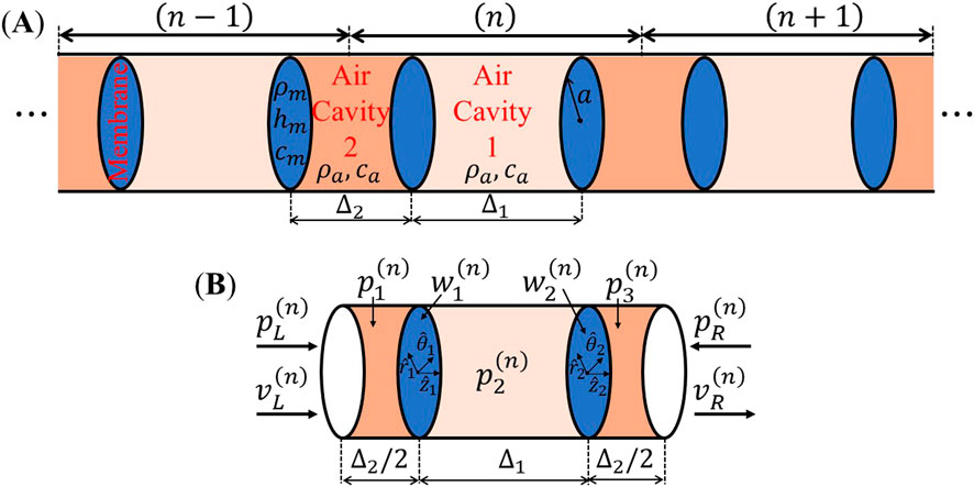
Figure 1. Schematic of the infinite vibroacoustic multilayered phononic metamaterial constructed by coupling alternating unit-cells (layers) consisting of half cavity 2 – membrane–cavity 1 – membrane–half cavity 2: (A) Three adjacent unit-cells, and (B) the
According to Bloch’s theorem, the change in wave amplitude between adjacent unit cells is independent of their specific locations within the lattice. Therefore, a complete characterization of wave propagation in the infinite periodic assembly can be achieved solely through analyzing a representative unit cell. In Figure 1B, the
A detailed analysis, based on the transfer matrix method, of a generalized version of this multilayered vibroacoustic lattice, where each unit cell is constructed from two distinct membranes and cavities, was recently reported in (Gzal et al., 2024b). However, the selection of the unit cell was different from our choice in the current study. Here, the unit cell is shifted (compared to the case in (Gzal et al., 2024b)) to preserve inversion symmetry. As a result, while the band structure remains identical and independent of the unit cell selection, the acoustic pressure distribution along the unit cell, as well as the components of the transfer matrix in this study, will be different from those derived in (Gzal et al., 2024b). Furthermore, altering the basis of the unit cell changes the geometric phase accumulated by the eigenmodes, such as changing the Zak phase from that of the unit cell in (Gzal et al., 2024b). Therefore, for the inversion symmetry case selected here, the governing equations and boundary conditions will be detailed, followed by the final analytical solution for the coupled vibroacoustic phononic lattice.
2.2 Equations of motion and boundary conditions
Omitting dissipation effects, we denote by
where
Here,
where
To analytically solve the coupled sound-structure problem defined by Equations 1–4, we follow the approach in (Gzal et al., 2024c), where the transverse displacements of the membranes were explicitly solved without assuming eigenfunction (modal) expansions; as discussed in (Gzal et al., 2024c) this is important in order to satisfy the boundary conditions without resorting to infinite series expansions whose truncation is problematic for accuracy purposes. To this, the steady-state solution of the problem is explicitly derived for axisymmetric modes operating in the low-frequency range
2.3 Analytical solution for the coupled sound-membrane vibroacoustic system
Let the steady-state axisymmetric acoustic pressure and velocity at the left edge of the
Where the amplitudes
In addition, the transverse deflection fields of the two membranes are given by:
Here,
Remarkably, Equations 5–8 satisfy the equations of motion Equation 1 and Equation 3 as well as the boundary conditions Equation 2 and Equation 4. The explicit expressions for the pressure amplitudes
2.4 Transfer matrix formalism
To construct the local transfer matrix for a single unit cell, we denote the acoustic state vectors at the left and right boundaries of the
The acoustic velocity compatibility and the pressure equilibrium at the junction between the
By definition, the local transfer matrix, denoted by
where the frequency-dependent components of
where,
As the considered system is time-invariant, linear, and possesses scalar material properties, the reciprocity principle holds (Jalas et al., 2013), necessitating that the local transfer matrix,
2.5 Local impedance, scattering matrices, and reflection-transmission spectra
Rearranging the terms in Equation 11 yields a relation between the acoustic pressures at the left and right boundaries of the
The symmetry of the local impedance matrix,
Another way to describe the acoustical behavior of the vibroacoustic lattice is by using the local scattering matrix, denoted by
By construction, the local scattering matrix, given in Equation 14, encodes the reflection and transmission coefficients, respectively denoted by
2.6 Band structure characterization
The band structure of the vibroacoustic phononic metamaterial with infinite unit cells is fully characterized using the Bloch-Floquet theorem, where the eigenvalues of the local transfer matrix are given by:
where
Moreover, the corresponding eigenvectors of matrix
According to Equation 16, wave propagation occurs when
3 Vibroacoustic topological interface states–the lattice of infinite extent
In this section, we outline a systematic approach to constructing vibroacoustic topological interface states by examining topological phase transitions through band structure evolution and symmetry analysis of band-edge pressure distributions. We then analyze the interface states in infinite lattices using the Zak phase, surface impedance, and reflection coefficients. Rather than relying on the straightforward expression of the Zak phase, we approach it through the transfer matrix perspective. While the Zak phase is a well-established tool for characterizing band topology, its abstract nature complicates the design of interface modes, particularly in complex systems like the proposed vibroacoustic system. To make the design of topological states more practical and physically insightful, we adopt the surface impedance concept. Through the transfer matrix formalism, we establish explicit criteria for the existence of topological interface states and, remarkably, derive a direct relation for locating these states based on the system’s physical parameters. Our analysis also uncovers new insights into the role of reflection coefficients in determining the location of interface states.
3.1 Construction of topological interface states
To study the topological properties of the multilayered vibroacoustic phononic metamaterial, we introduce a contrast parameter
where
The influence of the contrast parameter,
where,
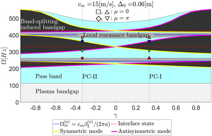
Figure 2. The six leading bandgaps/bands in the multilayered vibroacoustic metamaterial for varying contrast parameter (
In addition to preserving the unit-cell length, i.e.,
Consistently, the band-crossing phenomenon in Figure 2 occurs exclusively within the Bragg-like band-splitting induced bandgaps (or within the classical Bragg bandgaps that appear at high-frequencies) and not within the local resonance bandgaps. Within the range
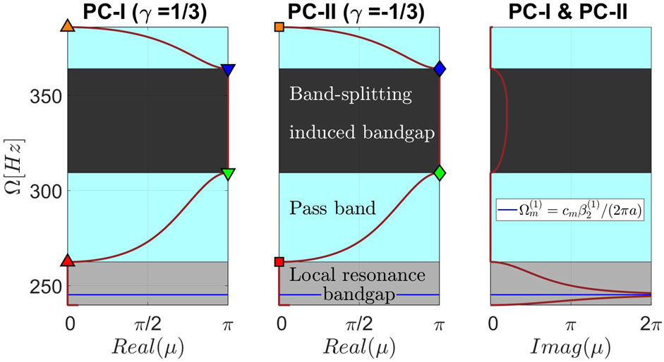
Figure 3. The third and fourth bands/bandgaps of the band structure for infinite lattices composed of uniform PC-I or PC-II unit-cells. Real and imaginary parts of the propagation constant,
Prior to examining the topological structures of infinite vibroacoustic lattices composed of PC-I or PC-II unit-cells, we utilize the derived analytical pressure distribution inside the three cavities along a representative unit-cell, as provided in Equation 6, to assess the symmetry of the eigenmodes at the bounding frequencies of the band-splitting induced bandgaps (i.e., band-edge states). To this end, the eigenmodes corresponding to
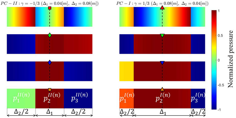
Figure 4. Acoustic pressure eigenfunctions (mode shapes) inside the three cavities along a representative unit cell, computed at the four bounding frequencies marked in Figures 2, 3 for the PC-I lattice configuration (right column) and the PC-II lattice configuration (left column).
To visualize the acoustic pressure eigenfunctions (mode shapes) within a representative unit-cell for PC-I and PC-II lattice configurations, we selected the four bounding frequencies that determine the edges of the third and fourth bands, i.e., band-edge states. These band-edge states are marked in Figure 2 by upward- and downward-pointing triangles for the PC-I configuration, and by squares and diamonds for the PC-II configuration. The exact locations of these selected band-edge states projected on the dispersion curves are illustrated in Figure 3 for both PC-I and PC-II lattice configurations, where the third and fourth bands/bandgaps of the band structure are presented. Visualizations of the corresponding pressure mode shapes, within a representative unit-cell for the PC-I and PC-II configurations, at these selected band-edge states frequencies are illustrated in Figure 4. For the PC-I configuration, the pressure eigenfunction associated with the cut-off frequency of the third band (green downward-pointing triangle) is symmetric, while the pressure eigenfunction associated with the cut-on frequency of the fourth band (blue downward-pointing triangle) is antisymmetric. However, these characteristics are inverted for the PC-II configuration, where the frequency of the symmetric mode becomes higher than that of the antisymmetric one. Therefore, PC-I and PC-II lattice configurations are topologically distinct despite their apparently identical band structures. The observed switching of the band-edge states is attributed to the band-inversion phenomenon, which has been previously exploited in electronic (Hasan and Kane, 2010), photonic (Xiao et al., 2014), and phononic (Wang et al., 2015) crystals to achieve localized states. Such localized states appear at the interface of two topologically distinct lattices, in the present case one with
Based on the aforementioned discussion, topological interface states can be realized at the interface of two connected lattices with different topological phases within a common bandgap. Figure 5 depicts the schematic of the composite lattice with the interface formed by two semi-infinite lattices with topologically distinct unit-cell configurations; namely, a right lattice composed of PC-I unit-cells (
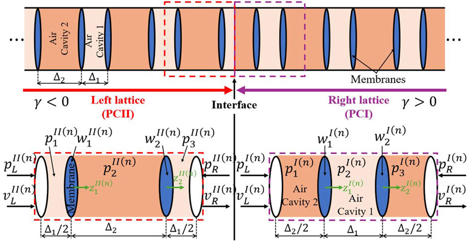
Figure 5. Schematic of the composite vibroacoustic lattice, composed of two semi-lattices with PC-I (right) and PC-II (left)unit-cells.
Superscripts “I” and “II” are used in Figure 5 to distinguish between the right lattice of PC-I unit-cells, and the left one of PC-II unit-cells, respectively. In the subsequent analysis, we will explore the physical mechanisms behind the formation of topological interface states in this composite lattice system from two perspectives: First, by examining the properties of the infinite lattice, and second, by analyzing the finite lattice formed by a limited number of PC-I and PC-II unit-cells.
3.2 Vibroacoustic topological interface states
In this section we employ the previous transfer matrix derivations to investigate the topological interface states in the composite lattice of infinite extent. To this end, let
In the following analysis we aim to study the emergence of localized topological modes at the interface of the two semi-infinite lattices (see Figure 5) employing different methodologies. We start with the classical approach based on the Zak phase.
3.2.1 Zak phase computation
The geometric phase concept, specifically the Zak phase (Zak, 1989), is recognized as a well-established method for understanding topological phase transitions and classifying the topological properties of bulk bands in 1D periodic systems. The Zak phase quantifies the geometric phase acquired over the Brillouin zone, enabling the classification of bulk bands in phononic systems. This quantization is directly tied to the emergence of topologically protected interface states, that is, of localized modes that appear at the boundaries between regions with distinct topological characteristics. Specifically, the Zak phase for the
where
Due to the inversion symmetry of the unit-cell and the derived analytical solution for the sound-membrane interaction, the Zak phase for the
The second approach for determining the Zak phase of the inversion-symmetric unit-cell relies on the components of the eigenvectors of the local transfer matrices,
Considering that
where
After determining the Zak phase for each band, the existence of an interface state is established by the summation of Zak phases below the gap. Specifically, if two unit-cells with different sums of Zak phases below the
3.2.2 Surface impedance
To bring the design of topological states to a practical level, providing physical insights and predictive design tools, we now consider an alternative approach for establishing topological interface modes in the infinite composite lattice based on surface impedance. The concept of surface impedance, which encodes surface scattering properties, was introduced in (Xiao et al., 2014) to describe the topological properties of bulk dispersion through the geometric (Zak) phases of the bulk bands. Remarkably, a rigorous relation was derived that relates the surface impedance of a 1D PC to its bulk properties through the geometric (Zak) phases of the bulk bands. This relation can be employed to determine the existence or absence of interface states at the interface between two PCs within a specific bandgap, as well as to determine the exact frequency of any such states if they exist. Specifically, it was shown that the condition for the formation of an interface state in the interfacial region between two 1D PCs, i.e., PC-I and PC-II in this case, is simply (Xiao et al., 2014),
where
Proposition: For the composite vibroacoustic lattice of infinite extent depicted in Figure 5, within an arbitrary
Proof: According to Equation 13, it is evident that the surface impedance components,
To determine the surface impedance components
where “Existence” (“Nonexistence”) indicates the presence (absence) of an interface state within the
To determine the location (i.e., the frequency) of the interface state, denoted by
When an interface state exists within the
Relation Equation 28 holds for any 1D unit-cell with inversion symmetry, regardless of the interface states. The combination of Equations 27, 28 provides the following relations that must be satisfied at an interface state in the composite lattice of infinite extent with inversion-symmetric unit cells:
To the best of our knowledge, such straightforward relations characterizing the interface states in terms of the local transfer matrix components have not been previously reported. A physical interpretation of relations Equation 29 will be provided in the next subsection.
After introducing the components of the local transfer matrices from Equations 22–29 and performing algebraic manipulations, the following transcendental frequency equation for determining the exact location of the interface state within the
where, the relations for
3.2.3 Reflection coefficients
Lastly, further perspective on the physical mechanism governing the formation of interface states in the composite vibroacoustic lattice of Figure 5, can be gained from the viewpoint of reflection coefficients for the component right (I) and left (II) semi-infinite lattices. From Equation 15, the corresponding reflection coefficients, denoted by
In addition, the interface state relations given in Equation 29 can be rearranged as follows:
While Equation 31 applies for any arbitrary frequency, the relations given in Equation 32 hold only at an interface frequency,
Interestingly, Equation 33 reveals that at the interface state frequency,
4 Vibroacoustic topological interface states–The lattice of finite extent
Thus far, the analysis of the topological interface states has been conducted in terms of the local transfer matrix of the composite vibroacoustic metamaterial of infinite extent composed of two semi-infinite left and right sub-lattices with different topological features. This analysis was performed independently of the number of unit-cells and without consideration of any boundary conditions. In this section, we consider the corresponding system of finite extent composed of only a finite number of coupled unit-cells. Specifically, the composite lattice described in Figure 5 is constructed by connecting two finite sub-lattices: The right sub-lattice consists of
By construction, both PC-I and PC-II sub-lattice configurations possess the same “spatial period” (
The acoustic state vectors of the finite composite lattice at the left- and right-most boundaries are denoted by
Based on the unimodularity of the transfer matrices
where the superscript “#” can be replaced with either “I” or “II”, indicating the components of matrices
In Equation 36, the relations
The existence of topological interface states in the finite composite lattice can be identified as peaks in the transmission spectra or dips in the reflection spectra measured at the interfacial region. To obtain the scattering (transmission and reflection) spectra for the composite lattice, we introduce the components of the global transfer matrix into the general formula for scattering spectra derived in (Gzal et al., 2024a). As a result, we obtain:
Here
An alternative way to analyze the topological interface states in the composite lattice is through the eigenfrequency spectrum of an appropriately defined frequency response (or transmission) function, where peaks in the transmission spectra, indicate resonant transmission (i.e., perfect transparency if the peaks reach unity). By applying different boundary conditions, defined in terms of acoustic pressure and velocity, at the left and right boundaries of the finite composite vibroacoustic lattice, one can derive characteristic equations for the corresponding natural frequencies. For example, imposing free-free boundary conditions, i.e.,
The roots of the characteristic equations provided in Equation 38 determine the eigenfrequency spectrum corresponding to the composite lattice with both edges free. Clearly, the condition
To demonstrate the insensitivity of the bulk eigenspectrum and the topological interface states to boundary conditions, we consider a different scenario where both edges of the finite composite lattice are fixed, i.e.,
The condition
While the insensitivity of topological interface states to the number of unit-cells within the finite composite lattice as well as to external boundary conditions is well known—largely attributed to topological protection that keeps these states localized and robust against perturbations—this has mainly been demonstrated numerically. Here, however, we systematically and rigorously prove these robust characteristics. It is worth noting that demonstrating the persistence of topological states becomes more challenging as the number of unit cells increases due to the need for extremely fine resolution. With our approach, however, this was achieved naturally.
5 Results and discussion
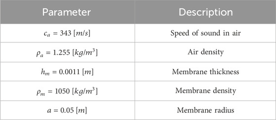
Unless stated otherwise, throughout this study the system parameters listed in Table 1 are considered. We used the actual values for air speed (
5.1 Demonstrating the existence of topological interface states
Panels (A) and (B) of Figure 6 present the six primary pass bands and bandgaps in the band structures for a vibroacoustic metamaterial with an infinite number of unit-cells, constructed uniformly with PC-I (
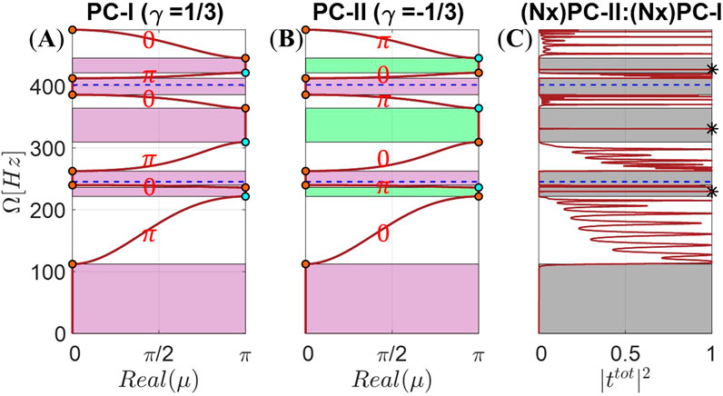
Figure 6. The six leading passbands and bandgaps of the band structure for a vibroacoustic metamaterial with an infinite number of uniform unit cells, with (A) PC-I (
Given that the summation of Zak phases below the second, fourth, and sixth bandgaps differs between the PC-I and PC-II configurations, edge states localized at the interface between the two PCs are expected within these bandgaps. Another indication of the non-trivial topological nature of these bandgaps is the difference in the sign of the imaginary part of
Although the existence of topological interface states was derived from the perspective of the infinite vibroacoustic lattices, the result in Figure 6C confirms the family of topological interface modes in the composite finite lattice. Specifically, the transmission spectrum, computed using Equation 37, for the composite finite lattice composed of a total of 10 unit-cells (5 PC-I unit-cells on the right and another 5 PC-II unit-cells on the left) confirms the topological character of the localized interface modes inside an infinite number of stopbands. The formation of these interface states, which in Figure 6C appear as resonant transmission peaks within the second, fourth, and sixth bandgaps, is evident and marked with black stars. The emergence of these interface states specifically within the even bandgaps, and not in others, can be attributed to the fact that as the contrast parameter
5.2 Determining the exact locations (frequencies) of topological interface states
After establishing the existence of interface states, determining their precise location within the corresponding topological bandgaps is of significant practical interest for predictive design of lattices with multi-frequency interface states. To this end, panel (A) of Figure 7 illustrates the imaginary parts of the local transfer matrix components,
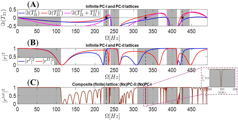
Figure 7. In panel (A) we depict the imaginary parts of the local transfer matrix components
Within the odd bandgaps shown in Figure 7A, both the PC-I (blue line) and PC-II (red line) configurations possess the same value of
Further physical insight on the interface states can be gained from the reflection coefficients of the infinite uniform lattices composed of PC-I or PC-II unit-cells. At an interface state, the reflection coefficients of these two topologically distinct lattices must intersect, as mathematically proven by Equation 33. This condition is illustrated in Figure 7B. The presence of topological interface states within the even bandgaps is also evident from the reflection spectrum, computed using Equation 37, for the composite finite vibroacoustic lattice of 10 PC-I and PC-II unit-cells, as shown in Figure 7C. Although the location of the interface states in the finite composite lattice was determined based on arguments involving the corresponding uniform infinite lattices, the formation of these localized states in the presented numerical results indicates their robustness with respect to the number of unit-cells of in the finite composite lattice, as was mathematically studied in Section 3.3.
5.3 Natural frequencies and mode shape of topological interface states
By definition, resonant transmission occurs at the natural frequencies of the finite composite vibroacoustic lattice, as given by Equation 38 for free boundary conditions, or by Equation 39 for fixed ones. The upper panel of Figure 8 illustrates the projection of the natural frequencies—indicated by black-edged circles—onto the third and fourth bands for a free-free multilayered vibroacoustic composite lattice consisting of 20 PC-I unit-cells on the right of the interface, and 20 PC-II unit-cells on the left. The emergence of an interface state within the fourth bandgap is evident, marked by a red-filled circle. The lower panel of Figure 8 depicts the acoustic pressure mode shape across the unit-cells for the interface mode. The strong localization of acoustic pressure at the interface between the two lattices is clearly shown.
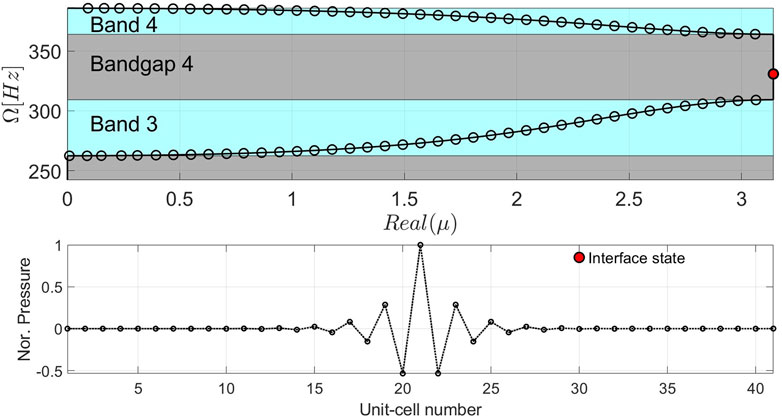
Figure 8. Projection of the natural frequencies (circles) for a free–free multilayered vibroacoustic composite lattice consisting of
5.4 Evolution of topological interface states
We have mathematically proven and numerically demonstrated the insensitivity of the topological interface states (modes) in the composite vibroacoustic multilayered lattice under “perturbations” including boundary conditions, number of unit-cells (in finite systems), and variations in system parameters. Specifically, we established the independence of these states from changes in the contrast parameter
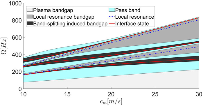
Figure 9. Evolution of the first three interface modes along with the corresponding band structure of the infinite multilayered vibroacoustic lattice as the nominal cavity depth is fixed to
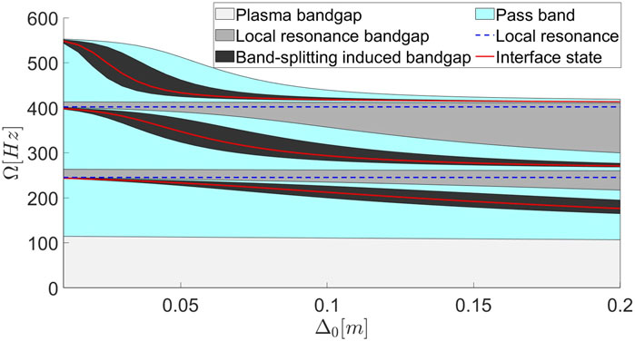
Figure 10. Evolution of the first three interface states along with the corresponding band structure of the infinite multilayered vibroacoustic lattice as the speed of elastic wave propagation in the membrane is fixed to
5.5 Delocalization phenomenon of interface states
Figure 11 depicts the localization behavior of the third interface state across points P1 to P6. For points P1 to P3, where the hosting bandgap is relatively wide, the interface state is strongly localized at the interfacial region. However, as the bandgap width decreases, the interface state becomes delocalized, merging with the bulk states, as shown for points P4 to P6. This hybridization results in mixed states that exhibit both strong localization at the interface and extended field distribution within the bulk. A similar delocalization behavior of edge states, accompanied by “mixed states,” has been recently reported in (Downing et al., 2019; Zhao et al., 2024) while investigating the topological phases of polaritons in a cavity waveguide modeled as an extended SSH model, where a breakdown of the bulk-edge correspondence was observed.
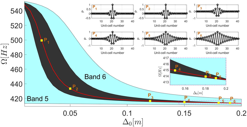
Figure 11. Delocalization of the third interface state, from Figure 10, in the topological phase as the nominal cavity depth (
5.6 Demonstrating the robustness of topological interface states
To rigorously assess the robustness of the interface states, we introduce random variations in the membrane wave speed as follows,
where
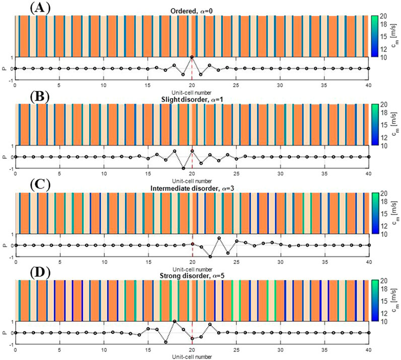
Figure 12. Sensitivity of interface states to varying levels of disorder in the membrane wave speed,
6 Concluding remarks
In this study, we systematically and rigorously explored the formation, evolution, and robustness of subwavelength topological interface states in a multilayered vibroacoustic phononic lattice composed of repetitive membrane-air cavity layers. Focusing on the challenging low-frequency range and assuming axisymmetric modes, we employed a purely analytical approach based on the transfer matrix formalism to analyze the interface states in inversion-symmetric unit cells. We began by solving the sound-membrane interaction problem in an exact manner within a representative unit-cell of an infinite multilayered vibroacoustic lattice, enabling a detailed characterization of its band structure. This led to the development of a systematic procedure for constructing topological interface states through phase transitions by coupling two topologically distinct semi-infinite vibroacoustic lattices. Through this framework, we derived analytical criteria for the existence of interface states based on three distinct concepts, namely, the Zak phase, surface impedance, and a newly proposed perspective based on reflection coefficients, all expressed in closed form through the components of the transfer matrix. Notably, we obtained an explicit expression for the exact location of the interface states, offering insight into their evolution and providing a practical guide for their design and realization. Furthermore, our analysis of the topological interface states within finite composite lattices demonstrated the robustness characteristic of these states against variations in the number of unit cells, as well as perturbations in system parameters and boundary conditions. Interestingly, beyond their typical strong localization at the interfacial region between two topologically distinct lattices, our findings reveal that as the width of the hosted bandgap narrows, the interface states begin to hybridize with the bulk, leading to a delocalization phenomenon. This delocalization not only offers new avenues in the design of these robust topological states but can also be harnessed to achieve tunable waveguiding and energy transfer in advanced metamaterial systems.
It is worth noting that the majority of previous studies on topological states relied heavily on finite element analysis, numerical simulations, or experimental verification to support primary analyses, often based on computational methods or analytical approximations such as infinite eigenmode expansions or effective medium theory. In contrast, our study presents an exact analysis of the interface states by directly solving the sound-membrane interaction problem in the low-frequency range, entirely free from infinite series truncations or other approximations. This precise methodology negates the need for further validation through approximated methods, highlighting the robustness and accuracy of our findings. Our work provides a comprehensive characterization of interface states purely through analysis, underscoring the strength of the transfer matrix method. Though originally derived for infinite lattices, this method enables a full characterization of interface states and offers direct physical insight into their behavior. Beyond its analytical rigor, our approach serves as a predictive design tool for practical topological lattices, paving the way for advances in applications of topological phenomena. This systematic approach is not only applicable to a broad range of vibroacoustic systems but can also be extended to other physical systems composed of repetitive unit cells with inversion symmetry, where subwavelength phenomena play a crucial role, including more general configurations of phononic and photonic crystals.
Moving forward, experimental validation will be essential for confirming the practical applicability of these results in real-world settings. These experiments will focus on verifying the robustness of the predicted topological interface states under disorder and material imperfections. Additionally, further research will explore the extension of the model to more complex multilayered systems and the incorporation of nonlinearities or non-Hermiticity to study their effects on the topological properties. Numerical simulations will complement both the analytical and experimental efforts, providing a comprehensive framework for potential practical applications in sound filters, waveguides, and acoustic sensors.
Data availability statement
The original contributions presented in the study are included in the article/Supplementary Material, further inquiries can be directed to the corresponding author.
Author contributions
MG: Conceptualization, Formal Analysis, Investigation, Methodology, Visualization, Writing–original draft, Writing–review and editing. JT: Conceptualization, Writing–review and editing. KM: Conceptualization, Writing–review and editing. AV: Conceptualization, Funding acquisition, Writing–review and editing.
Funding
The author(s) declare that financial support was received for the research, authorship, and/or publication of this article. The authors declare financial support was received for the research and authorship of this article. The research was financially supported by the Israeli Council of Higher Education (CHE-VATAT) and the Department of Mechanical Science and Engineering (MechSE) at the University of Illinois Urbana-Champaign.
Acknowledgments
The authors declare that there were no contributions or discussions related to this research beyond those of the listed authors.
Conflict of interest
The authors declare that the research was conducted in the absence of any commercial or financial relationships that could be construed as a potential conflict of interest.
The author(s) declared that they were an editorial board member of Frontiers, at the time of submission. This had no impact on the peer review process and the final decision.
Publisher’s note
All claims expressed in this article are solely those of the authors and do not necessarily represent those of their affiliated organizations, or those of the publisher, the editors and the reviewers. Any product that may be evaluated in this article, or claim that may be made by its manufacturer, is not guaranteed or endorsed by the publisher.
Supplementary material
The Supplementary Material for this article can be found online at: https://www.frontiersin.org/articles/10.3389/facou.2024.1489401/full#supplementary-material
References
Atala, M., Aidelsburger, M., Barreiro, J. T., Abanin, D., Kitagawa, T., Demler, E., et al. (2013). Direct measurement of the Zak phase in topological Bloch bands. Nat. Phys. 9, 795–800. doi:10.1038/nphys2790
Bansil, A., Lin, H., and Das, T. (2016). Colloquium: topological band theory. Rev. Mod. Phys. 88, 021004. doi:10.1103/revmodphys.88.021004
Bernevig, A. B., and Hughes, T. L. (2013). Topological insulators and topological superconductors. Princeton, NJ: Princeton University Press.
Chaunsali, R., Chen, C.-W., and Yang, J. (2018). Subwavelength and directional control of flexural waves in zone-folding induced topological plates. Phys. Rev. B 97, 054307. doi:10.1103/physrevb.97.054307
Chiu, C.-K., Teo, J. C. Y., Schnyder, A. P., and Ryu, S. (2016). Classification of topological quantum matter with symmetries. Rev. Mod. Phys. 88, 035005. doi:10.1103/revmodphys.88.035005
Darabi, A., and Leamy, M. J. (2019). Reconfigurable topological insulator for elastic waves. J. Acoust. Soc. Am. 146, 773–781. doi:10.1121/1.5114920
Downing, C. A., Sturges, T. J., Weick, G., Stobi´nska, M., and Mart´ın-Moreno, L. (2019). Topological phases of polaritons in a cavity waveguide. Phys. Rev. Lett. 123, 217401. doi:10.1103/physrevlett.123.217401
Fleury, R., Khanikaev, A. B., and Alù, A. (2016). Floquet topological insulators for sound. Nat. Comm. 7, 11744. doi:10.1038/ncomms11744
Gzal, M., Vakakis, A. F., and Gendelman, O. V. (2024c). Vibroacoustics of a membrane-finite cavity resonator: traditional and alternative approaches for analysis. J. Sound. Vib. 573, 118214. doi:10.1016/j.jsv.2023.118214
Gzal, M. O., Bergman, L. A., Matlack, K. H., and Vakakis, A. F., Analytical study of a monolayered vibroacoustic metamaterial, arXiv:2408.09660 (2024a).
Gzal, M. O., Bergman, L. A., Matlack, K. H., and Vakakis, A. F., Sub-bragg phenomena in multilayered vibroacoustic phononic metamaterials, arXiv:2410.01178 (2024b).
Haldane, F. D. M., and Raghu, S. (2008). Possible realization of directional optical waveguides in photonic crystals with broken time-reversal symmetry. Phys. Rev. Lett. 100, 013904. doi:10.1103/physrevlett.100.013904
Harari, G., Bandres, M. A., Lumer, Y., Rechtsman, M. C., Chong, Y. D., Khajavikhan, M., et al. (2018). Topological insulator laser: theory. Science 359, aar4003. doi:10.1126/science.aar4003
Hasan, M. Z., and Kane, C. L. (2010). Colloquium: topological insulators. Rev. Mod. Phys. 82, 3045–3067. doi:10.1103/revmodphys.82.3045
He, C., Ni, X., Ge, H., Sun, X., Chen, Y., Lu, M., et al. (2016). Acoustic topological insulator and robust one-way sound transport. Nat. Phys. 12, 1124–1129. doi:10.1038/nphys3867
He, H., Qiu, C., Ye, L., Cai, X., Fan, X., Ke, M., et al. (2018). Topological negative refraction of surface acoustic waves in a Weyl phononic crystal. Nature 560, 61–64. doi:10.1038/s41586-018-0367-9
Jalas, D., Petrov, A., Eich, M., Freude, W., Fan, S., Yu, Z., et al. (2013). What is — and what is not — an optical isolator. Nat. Phot 7, 579–582. doi:10.1038/nphoton.2013.185
Kliewer, E., Darabi, A., and Leamy, M. J. (2021). Additive manufacturing of channeled acoustic topological insulators. J. Acoust. Soc. Am. 150 (4), 2461–2468. doi:10.1121/10.0006452
Lu, J., Qiu, C., Ke, M., and Liu, Z. (2016). Valley vortex states in sonic crystals. Phys. Rev. Lett. 116, 093901. doi:10.1103/physrevlett.116.093901
Lu, L., Joannopoulos, J., and Soljačić, M. (2014). Topological photonics. Nat. Phot. 8, 821–829. doi:10.1038/nphoton.2014.248
Ma, G., Xiao, M., and Chan, C. T. (2019). Topological phases in acoustic and mechanical systems. Nat. Rev. Phys. 1, 281–294. doi:10.1038/s42254-019-0030-x
Mei, J., Ma, G., Yang, M., Yang, Z., Wen, W., and Sheng, P. (2012). Dark acoustic metamaterials as super absorbers for low-frequency sound. Nat. Comm. 3, 756. doi:10.1038/ncomms1758
Miniaci, M., Pal, R. K., Morvan, B., and Ruzzene, M. (2018). Experimental observation of topologically protected helical edge modes in patterned elastic plates. Phys. Rev. X 8, 031074. doi:10.1103/physrevx.8.031074
Morse, P. M. (1948). Vibration and sound. second edition. New York: McGraw-Hill Book Company, Inc., 200–203.
Mousavi, S. H., Khanikaev, A. B., and Wang, Z. (2015). Topologically protected elastic waves in phononic metamaterials. Nat. Comm. 6, 8682. doi:10.1038/ncomms9682
Pal, R. K., and Ruzzene, M. (2017). Edge waves in plates with resonators: an elastic analogue of the quantum valley Hall effect. New J. Phys. 19, 025001. doi:10.1088/1367-2630/aa56a2
Peng, Y., Qin, C., Zhao, D., Shen, Y., Xu, X., Bao, M., et al. (2016). Experimental demonstration of anomalous Floquet topological insulator for sound. Nat. Comm. 7, 13368. doi:10.1038/ncomms13368
Qi, X.-L., and Zhang, S.-C. (2011). Topological insulators and superconductors. Rev. Mod. Phys. 83, 1057–1110. doi:10.1103/revmodphys.83.1057
Rechtsman, M. C., Zeuner, J. M., Plotnik, Y., Lumer, Y., Podolsky, D., Dreisow, F., et al. (2013). Photonic floquet topological insulators. Nature 496, 196–200. doi:10.1038/nature12066
Segev, M., and Bandres, M. A. (2021). Topological photonics: where do we go from here? Nanophot 10, 425–434. doi:10.1515/nanoph-2020-0441
Su, W. P., Schrieffer, J. R., and Heeger, A. J. (1979). Solitons in polyacetylene. Phys. Rev. Lett. 42, 1698–1701. doi:10.1103/physrevlett.42.1698
Su, W. P., Schrieffer, J. R., and Heeger, A. J. (1980). Soliton excitations in polyacetylene. Phys. Rev. B 22, 2099–2111. doi:10.1103/physrevb.22.2099
Vila, J., Pal, R. K., and Ruzzene, M. (2017). Observation of topological valley modes in an elastic hexagonal lattice. Phys. Rev. B 96, 134307. doi:10.1103/physrevb.96.134307
von Klitzing, K. (1986). The quantized Hall effect. Rev. Mod. Phys. 58, 519–531. doi:10.1103/revmodphys.58.519
von Klitzing, K., Dorda, G., and Pepper, M. (1980). New method for high-accuracy determination of the fine-structure constant based on quantized Hall resistance. Phys. Rev. Lett. 45, 494–497. doi:10.1103/physrevlett.45.494
Wang, P., Lu, L., and Bertoldi, K. (2015). Topological phononic crystals with one-way elastic edge waves. Phys. Rev. Lett. 115, 104302. doi:10.1103/physrevlett.115.104302
Wang, Q., Xiao, M., Liu, H., Zhu, S., and Chan, C. T. (2016). Measurement of the Zak phase of photonic bands through the interface states of a metasurface/photonic crystal. Phys. Rev. B 93, 041415. doi:10.1103/physrevb.93.041415
Wang, Z., Chong, Y., Joannopoulos, J., and Soljačić, M. (2009). Observation of unidirectional backscattering immune topological electromagnetic states. Nature 461, 772–775. doi:10.1038/nature08293
Wang, Z., Chong, Y. D., Soljačić, M., and Soljačić, M. (2008). Reflection-free one-way edge modes in a gyromagnetic photonic crystal. Phys. Rev. Lett. 100, 013905. doi:10.1103/physrevlett.100.013905
Wielian, R., Toftul, I., and Kivshar, Y. S., Transfer matrix approach for topological edge states, arXiv:2406.01005 (2024).
Xiao, M., Chen, W., He, W., and Chan, C. T. (2015a). Synthetic gauge flux and Weyl points in acoustic systems. Nat. Phys. 11, 920–924. doi:10.1038/nphys3458
Xiao, M., Ma, G., Yang, Z., Sheng, P., Zhang, Z. Q., and Chan, C. T. (2015b). Geometric phase and band inversion in periodic acoustic systems. Nat. Phys. 11, 240–244. doi:10.1038/nphys3228
Xiao, M., Zhang, Z. Q., and Chan, C. T. (2014). Surface impedance and bulk band geometric phases in one-dimensional systems. Phys. Rev. X 4, 021017. doi:10.1103/physrevx.4.021017
Xue, H., Yang, Y., and Zhang, B. (2022). Topological acoustics. Nat. Rev. Mat. 7, 974–990. doi:10.1038/s41578-022-00465-6
Yang, Z., Dai, H., Chan, N., Ma, G., and Sheng, P. (2010). Acoustic metamaterial panels for sound attenuation in the 50–1000Hz regime. Appl. Phys. Lett. 96, 041906. doi:10.1063/1.3299007
Yang, Z., Gao, F., Shi, X., Lin, X., Gao, Z., Chong, Y. D., et al. (2015). Topological acoustics. Phys. Rev. Lett. 114, 114301. doi:10.1103/physrevlett.114.114301
Yin, J., Ruzzene, M., Wen, J., Yu, D., Cai, L., and Yue, L. (2018). Band transition and topological interface modes in 1D elastic phononic crystals. Sci. Rep. 8 (1), 6806. doi:10.1038/s41598-018-24952-5
Yves, S., Fleury, R., Lemoult, F., Fink, M., and Lerosey, G. (2017). Topological acoustic polaritons: robust sound manipulation at the subwavelength scale. New J. Phys. 19, 075003. doi:10.1088/1367-2630/aa66f8
Zak, J. (1989). B’errys phase for energy bands in solids. Phys. Rev. Lett. 62, 2747–2750. doi:10.1103/physrevlett.62.2747
Zhang, X., Xiao, M., Cheng, Y., Lu, M.-H., and Christensen, J. (2018). Topological sound. Comm. Phys. 1, 97. doi:10.1038/s42005-018-0094-4
Zhang, Z., Wei, Q., Cheng, Y., Zhang, T., Wu, D., and Liu, X. (2017). Topological creation of acoustic pseudospin multipoles in a flow-free symmetry-broken metamaterial lattice. Phys. Rev. Lett. 118, 084303. doi:10.1103/physrevlett.118.084303
Zhao, D., Wang, Z., Yang, L., Zhong, Y., Xi, X., Zhu, Z., et al. (2024). Observation of tunable topological polaritons in a cavity waveguide. arXiv:2401, 10450.
Keywords: vibroacoustic metamaterial, Zak phase, surface impedance, local resonance bandgap, plasma bandgap, sub-Bragg bandgaps, topological interface modes
Citation: Gzal MO, Tempelman JR, Matlack KH and Vakakis AF (2024) Subwavelength topological interface modes in a multilayered vibroacoustic metamaterial. Front. Acoust. 2:1489401. doi: 10.3389/facou.2024.1489401
Received: 01 September 2024; Accepted: 23 October 2024;
Published: 11 November 2024.
Edited by:
Raj Kumar Pal, Kansas State University, United StatesReviewed by:
Zhongtao Hu, Beihang University, ChinaMurat Kaynak, Harvard Medical School, United States
Copyright © 2024 Gzal, Tempelman, Matlack and Vakakis. This is an open-access article distributed under the terms of the Creative Commons Attribution License (CC BY). The use, distribution or reproduction in other forums is permitted, provided the original author(s) and the copyright owner(s) are credited and that the original publication in this journal is cited, in accordance with accepted academic practice. No use, distribution or reproduction is permitted which does not comply with these terms.
*Correspondence: Majdi O. Gzal, Z3phbEBpbGxpbm9pcy5lZHU=
 Majdi O. Gzal
 Joshua R. Tempelman2
 Kathryn H. Matlack