 Themistoklis Tsalkatidis
 Youcef Amara2
 Samuel Embaye
 Einar Nathan
- 1Faculty of Science and Technology, Norwegian University of Life Sciences, Ås, Norway
- 2UnionConsult, Oslo, Norway
Hybrid steel to timber connections are found in many buildings and bridges. These connections offer several advantages such as ease of construction and energy dissipation. This research paper aims to study the mechanical behavior of bolted hybrid connections that consists of a square hollow steel column (SHS) and a glulam timber beam. The connection between the two structural members is achieved by means of angles and preloaded bolts. A reference model is constructed and verified by comparison to experimental and numerical data from the international literature. Additionally, several parameters that affect the response of the connection are modified in order to investigate and quantify their effect, resulting in seven different case studies. These parameters are the size of the bolts, the thickness of the angles and the addition of stiffener. The moment-rotation curve of each case study is constructed and the results are commented. Finally, a proposed optimal configuration of the hybrid connection is presented.
Introduction
Steel and wood are materials that have been extensively used in constructions worldwide, even from ancient times. Nowadays, the need for a sustainable built environment encourages structural engineers to think of new design options that can maximize the benefits of the aforementioned materials. By combining the strength and ductility of steel with the low weight of wood, environmental friendly structures are achieved. The structural members in this type of constructions are connected using hybrid solutions. In countries like Norway where the access to wood resources is easy, these hybrid structures could become the norm for future lightweight structures.
Methods
Problem Formulation
Connections between steel and concrete or steel and timber structural elements are referred as hybrid. In general, the design of connections between members is always a challenge for the structural engineers. Loads and stresses need to be transferred from one structural member to another. In the presented paper, finite element modeling is used as a tool to investigate the behavior of hybrid bolted steel- timber connections considering several proposals made in technical literature, such as Amara and Embaye (2017). This type of connections has not been thoroughly examined. The numerical simulations of the hybrid connections under study are governed by the contact conditions at the steel-timber interface. Emphasis is placed on the construction of moment-rotation curves of the connections. Only the elastic stiffness of the connection is determined since elastic design is traditionally selected in the case of connections. The reference beam to column hybrid connection is depicted in Figure 1.
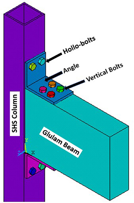
Figure 1. Rendering of the reference connection, figure based on Karagiannis et al. (2017).
Moment-Rotation Curve
In structural engineering, the behavior of a certain structure under design load situations is represented by unique action-deformation curves. If the structure is examined at member level then the moment-rotation (M-ϕ) curve represents the behavior of a certain connection between structural members. The rotational stiffness of the connection is equal to the slope of the curve and the initial value of this stiffness is used for the classification of the connection, which is important for the design of MRFs. According to Eurocode 3 part 1.8 (EN 1993-1-8, 2005), a connection can be classified as pinned, semi-rigid or rigid, if it satisfies the respective criteria presented below in Equations (1)–(5):
where:
Sj, ini is the initial rotational stiffness of the connection (kN/mrad)
EIb is the bending stiffness of the beam (kN/mrad)
Lb is the span of the beam (mm)
The classification of the joint according to the initial rotational stiffness presented in Eurocode 3 (EN 1993-1-8, 2005) and Eurocode 5 (EN 1995-1-1, 2004) is depicted in Figure 2. The M-ϕ curve can be either non-linear or have a simplified tri-linear or even bi-linear form as described in Eurocode 3. In our analysis, only the first linear branch of the M-ϕ curve is plotted since it is adequate to classify the hybrid connections when performing elastic analysis of connections at the Serviceability Limit State (SLS).
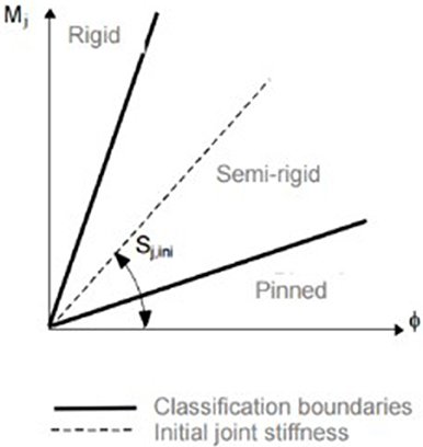
Figure 2. Connection classification by initial rotational stiffness, figure from Eurocode (EN 1993-1-8, 2005).
Analytical Solution
The general procedure for determining the rotational stiffness of a connection proposed by Eurocode (EN 1993-1-8, 2005) is the component method. The key idea of this method is to calculate the stiffness of all the components of a connection and then the total stiffness by assembling a mechanical model of the whole system of elementary springs. The components of a connection are the connected parts and the connecting elements. Of course, the identification of the active components of the connection and the evaluation of their contribution according to Porteous and Kermani (2013) must be done in the beginning. The problem with this method is that it cannot be applied in hybrid connections without assumptions. These assumptions are often very conservative thus leading to overdesigned connection solutions. Therefore, the following method is used. First, the rotation ϕ of the connection is calculated, for every load step, using the trigonometric Equation (6), neglecting the elastic deformation of the column:
where:
ϕ is the rotation of the connection (mrad)
Δe is the elastic deformation of the beam (mm)
db is the depth of the beam (mm)
Then, the reaction force Pe, as shown in Figure 3, is calculated using the Eq. (7):
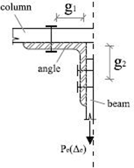
Figure 3. Analytical solution of semi-rigid angle connection, figure based on Lee and Moon (2002).
where:
Pe is the reaction force (kN)
g1 is the gauge distance parallel to the column (mm)
g2 is the gauge distance parallel to the beam (mm)
Finally, the elastic moment of the connection is found, using the Equation (8):
where:
M is the elastic moment of the connection (kNm)
le is the effective length of the angle (mm)
Equations (7) and (8) together with the corresponding Figure 3, are empirical analytical formulas that are valid for semi- rigid connections with angles. These formulas were proposed by Lee and Moon (2002) and predict accurately the early response of the connection.
The final step is to construct the moment-rotation curve and to calculate the initial rotational stiffness, which is equal to the slope of the M-ϕcurve. The calculation is done using the Equation (9):
where:
Sj, ini is the initial rotational stiffness of the connection (kN/mrad)
Numerical Analysis
Reference Model
The reference beam-column hybrid connection consists of glulam beam and a steel SHS column. The beam has a height of 405 mm and width of 140 mm, whereas the column is 150 mm wide and 10 mm thick. Top and seat angles are 150*200 mm, 15 mm thick and they are connected using M12 HR bolts to the glulam beam and M16 HR bolts to the tubular steel column, respectively. The steel grade of the column is S355, of the top and seat angle is S275 and of the bolts. Glulam is of category GL28h. The model is constructed according to the geometric and mechanical characteristics of an experimental specimen found in the international literature by Karagiannis et al. (2017). The reference model does not have blind bolts penetrating the SHS column for simplicity reasons although mechanical models that describe the behavior of blind-bolted angle connections have been proposed by Malaga-Chuquitaype and Elghazouli (2010). In this paper, the focus is on the effect of the different components on the connection by Anwar and Najam (2016), in relation to the strength and the rotational stiffness of the joint. The support and loading conditions of the three-dimensional finite element simulation are the same as the experiment by Karagiannis et al. (2017) for verification purposes.The displacement-induced load at the end of the beam is limited to 7mm in order the behavior of the joint to remain elastic. Only one quarter of the joint is modeled due to symmetry. The model is constructed using ANSYS version 17.2 finite element package (Ansys Inc., 2017). Figure 4 depicts the comparison of the moment-rotation curve between the numerical and the experimental analysis, within the elastic response of the connection.
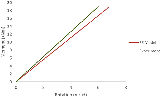
Figure 4. Verification of numerical model.
The beam, the column and the angles are simulated with three-dimensional structural solid finite elements and the contact interfaces with surface-to-surface contact elements. Contact, itself, is a complex phenomenon that adds nonlinearities to a finite element simulation as presented by Bathe (1996) and Mistakidis and Stavroulakis (1998). In the case of hybrid connections, the interaction of different materials adds an extra level of difficulty. ANSYS software offers the option of pair-based contact where one surface is regarded as the contact and the other as the target one. The interface behavior is set as bonded with a Coulomb coefficient of friction equal to 0.7 in order to simulate unilateral frictional contact conditions described by Popov (2010) and Tsalkatidis and Avdelas (2010). The contact elements overlay the solid elements and the contact is detected at Gauss points. The pretension of the bolts and the resulting clamping forces are modeled by using the PRETS179 element from the ANSYS library. As stated before, the blind bolts of the experimental specimen are replaced by bolts with nuts.
Case Studies
A total number of seven case studies is examined by Amara and Embaye (2017), as presented in the Table 1. The parameters examined are the thickness of the angles (case studies 2, 3, and 7), the diameter of the vertical bolts (case studies 4 and 5), the width of the angles (case study 6) and the addition of stiffener (case study 7). The aforementioned parameters have been examined in several research studies such as Theofanous et al. (2015), Tartaglia et al. (2018), and Gil et al. (2015).
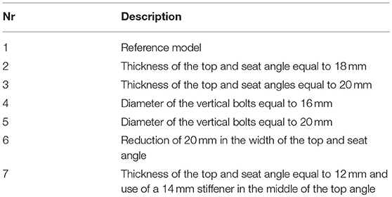
Table 1. Case studies examined.
Results
The main results of the numerical analysis are the moment-rotation curves together with the corresponding initial rotational stiffness and the von Mises stresses that develop in the connection. The results are presented in Figures 5–10.
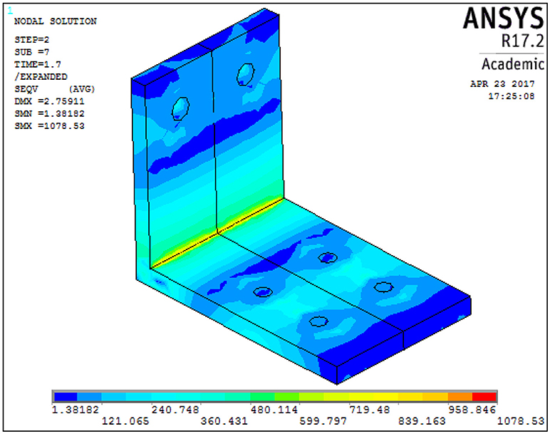
Figure 5. Von Mises stress distribution in the top angle for case 1.
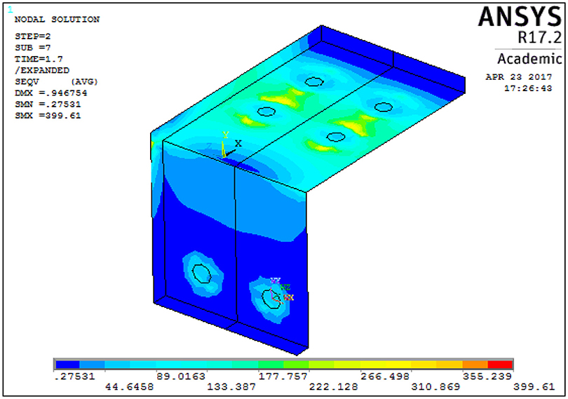
Figure 6. Von Mises stress distribution in the seat angle for case 1.
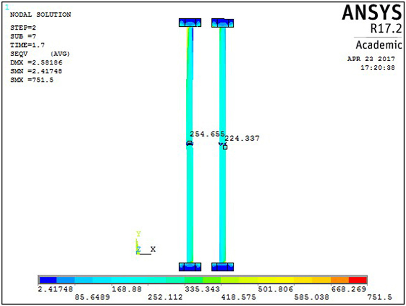
Figure 7. Von Mises stress distribution in the vertical bolts for case 1.
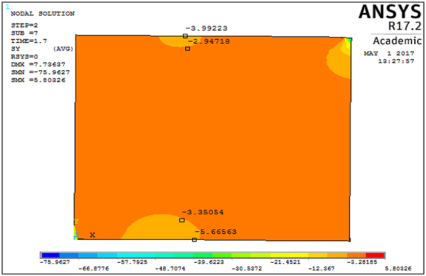
Figure 8. Von Mises stress distribution in the glulam beam for case 1.
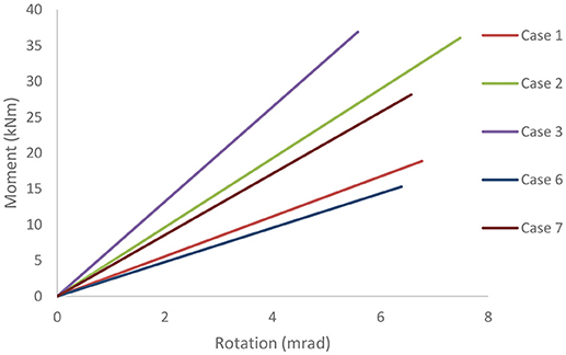
Figure 9. Numerical moment-rotation curves.
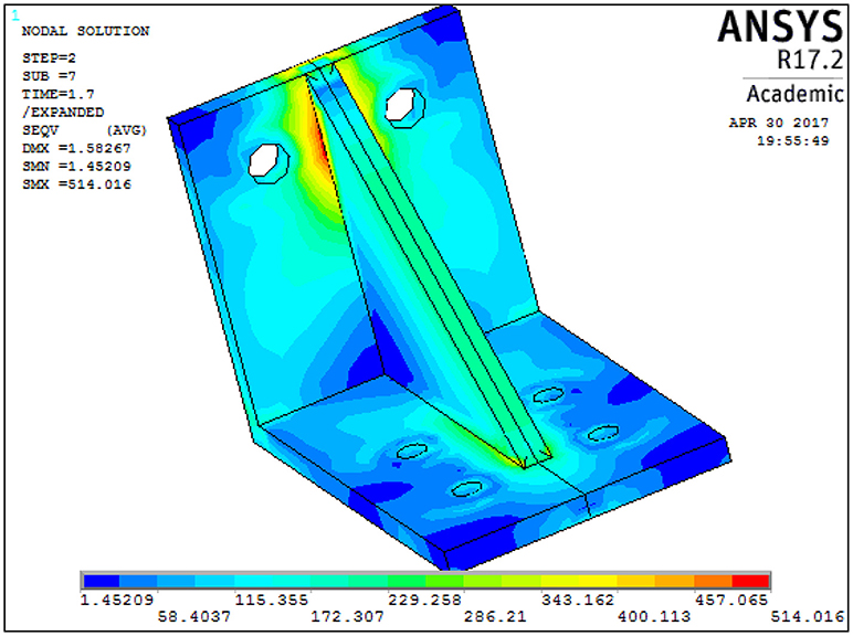
Figure 10. Von Mises stress distribution in the top angle for case 7.
Discussion and Conclusion
The numerical analysis of the hybrid steel-timber connection focuses on the initial rotational stiffness and the developing von Mises stresses in the top angle.
Effect of angle thickness
• By changing the thickness of the top and the seat angles from 15 mm (case study 1) to 18 mm (case study 2) or to 20 mm (case study 3), the rotational stiffness of the connection increases. For case 2 the increase is 73% and for case 3 is 137%, in comparison to case 1. This denotes that even a small increase in thickness of the angles has a significant effect on the rotational stiffness of the connection. As expected, the connection becomes stiffer when the thickness of the angles is increased. Moreover, the maximum von Mises stress in the top angle is decreased by 12.2% in case 2 and by 15.5 % in case 3. The increase in the amount of steel used is 21 and 35.2%, respectively.
Effect of bolt diameter
• By changing the diameter of the vertical bolts from12 mm (case study 1) to 16 mm (case study 4) or to 20 mm (case study 5), the rotational stiffness of the connection is not affected. The change in the diameter of the bolts is reciprocal to the change in the pretension force. Moreover, the maximum von Mises stress in the top angle is decreased by 20.7% in case 4 and by 32.7% in case 5. The increase in the amount of used steel is higher by 21 and 35.2%, respectively.
Effect of angle width
• By reducing the width of the of the top and the seat angles from 150 mm (case study 1) to 130 mm (case study 6), the rotational stiffness of the connection is reduced by 14.15%. Moreover, the maximum von Mises stress in the top angle increases by 14.28%.
Effect of stiffener
• By adding a stiffener at the top angle (case study 7), the rotational stiffness of the connection increases by 53.6% in relation to the reference model. The addition of stiffener leads to the development of high von Mises stresses in the seat angle near the bolt heads due to bending of the horizontal leg of the seat angle. After the pretension of the bolt, the stiffener also enhances the clamping forces at the bolt-angle interface.
• Local surface crushing of the glulam beam is present in all models, due to compression from the top and seat angle. The effect is more significant when the stiffness of the angle is higher, thus resulting in a huge difference in deflection between the beam and the angle.
• The connection in all the case studies remains semi-rigid, as assumed. Case studies 2, 3, and 7 have the higher values of initial rotational stiffness. The von Mises stress in case study 5 has its minimum value.
• The recommended connection is a combination of case studies 3 and 5. The geometry of the joint remains the same, as in the reference model, but the thickness of both angles and the diameter of the bolts are set equal to 20 mm. This design option increases the initial rotational stiffness of the connection by 137%, whereas the von Mises stress decreases by at least 32.7%. The aforementioned benefits in the response of the connection by far outweigh the increase in steel use.
Author Contributions
TT, YA, and SE contributed conception, design of the study, and performed the analysis; TT wrote the first draft of the manuscript; TT, YA, SE, and EN wrote sections of the manuscript. All authors read and approved the submitted manuscript version.
Conflict of Interest Statement
The authors declare that the research was conducted in the absence of any commercial or financial relationships that could be construed as a potential conflict of interest.
References
Amara, Y., and Embaye, S. (2017). Analyzing the Behaviour of a Hybrid Steel to Timber Connection by Modifying Different Parameters. dissertation/master's thesis, Norwegian University of Life Sciences, Ås.s
EN 1993-1-8 (2005). Eurocode 3: Design of Steel Structures, Part 1–8: Design of Joints. Brussels: CEN.
EN 1995-1-1 (2004). Eurocode 5: Design of Timber Structures, Part 1–1: General Common Rules and Rules for Buildings. Brussels: CEN.
Gil, B., Bijlaard, F., and Bayo, E. (2015). T-stub behavior under out-of-plane bending. II: parametric study and analytical characterization. Eng. Struct. 98, 242–250. doi: 10.1016/j.engstruct.2015.03.039
Karagiannis, V., Malaga-Chuquitaype, C., and Elghazouli, A. Y. (2017). Behavior of hybrid timber beam-to-column moment connections. Eng. Struct. 131, 243–263. doi: 10.1016/j.engstruct.2016.11.006
Lee, S. S., and Moon, T. S. (2002). Moment rotational model of semi rigid connection with angles. Eng. Struct. 24, 227–237. doi: 10.1016/S0141-0296(01)00066-9
Malaga-Chuquitaype, C., and Elghazouli, A. Y. (2010). Component-based mechanical models for blind-bolted angle connection. Eng. Struct. 32, 3048–3067. doi: 10.1016/j.engstruct.2010.05.024
Mistakidis, E. S., and Stavroulakis, G. E. (1998). Non Convex Optimization and its Applications: Non Convex Optimization in Mechanics. Dordrecht: Kluwer Academic Publishers. doi: 10.1007/978-1-4615-5829-3
Popov, V. L. (2010). Contact Mechanics and Friction. Berlin: Springer-Verlag. doi: 10.1007/978-3-642-10803-7
Porteous, J., and Kermani, A. (2013). Structural Timber Design to Eurocode. Oxford: Wiley-Blackwell.
Tartaglia, R., D'Aniello, M., and Landolfo, R. (2018). The influence of rib stiffeners on the response of extended end-plate joints. J. Const. Steel Res. 148, 669–690. doi: 10.1016/j.jcsr.2018.06.025
Theofanous, M., Liew, A., and Gardner, L. (2015). Experimental study of stainless steel angles and channels in bending. Structures 4, 80–90. doi: 10.1016/j.istruc.2015.10.004
Keywords: FEM analysis, parametric investigation, hybrid steel-timber connections, bolted connections, hollow sections
Citation: Tsalkatidis T, Amara Y, Embaye S and Nathan E (2018) Numerical Investigation of Bolted Hybrid Steel-Timber Connections. Front. Built Environ. 4:48. doi: 10.3389/fbuil.2018.00048
Received: 02 July 2018; Accepted: 29 August 2018;
Published: 27 September 2018.
Edited by:
George C. Tsiatas, University of Patras, GreeceReviewed by:
Mario D'Aniello, Università degli Studi di Napoli Federico II, ItalyMassimo Latour, Università degli Studi di Salerno, Italy
Copyright © 2018 Tsalkatidis, Amara, Embaye and Nathan. This is an open-access article distributed under the terms of the Creative Commons Attribution License (CC BY). The use, distribution or reproduction in other forums is permitted, provided the original author(s) and the copyright owner(s) are credited and that the original publication in this journal is cited, in accordance with accepted academic practice. No use, distribution or reproduction is permitted which does not comply with these terms.
*Correspondence: Themistoklis Tsalkatidis, dGhlbWlzdG9rbGlzLnRzYWxrYXRpZGlzQG5tYnUubm8=