 Naqeeb Ul Islam
 R. S. Jangid
- Department of Civil Engineering, Indian Institute of Technology Bombay, Mumbai, India
Passive energy dissipation devices or supplemental damping devices have been successfully implemented into structures for controlling the excessive vibrations under wind and seismic excitation. Recent developments in the form of negative stiffness dampers (NSDs) and inerter-based vibration absorbers (IVAs) as potential energy dissipation devices are of considerable interest to researchers. The present study evaluates the performance of the combined NSD and IVA as a possible alternative to the traditional energy dissipation devices such as viscous dampers (VDs) and viscoelastic dampers (VEDs). The mathematical formulation and optimal design of the combined NSD and IVA mechanism are presented. A 20-storey benchmark building is modeled as a multi-degree-of-freedom (MDOF) shear building. The dynamic equations for the MDOF building are written in the state-space form, and a simple optimization approach based on effective modal damping is prescribed. Comparative performance between traditionally applied and novel IVA and NSD is investigated. The design considerations to analyze structures employing combined NSDs and IVAs are developed. It is demonstrated that NSDs and IVA-based passive energy dissipation devices are the most efficient devices in reducing inter-storey drifts and floor accelerations compared with VDs and VEDs using the same damping coefficient.
Introduction
Vibrations induced to a structure due to different kinds of dynamic loading such as winds, earthquakes, or vibrating machinery need special design steps for mitigating the adverse effects. Traditional strength-based or ductility-based design methods have limitations of higher construction cost and permanent damage to the structures. Due to these limitations, researchers have developed intelligent structure systems or structural control systems (Cheng et al., 2008; Saaed et al., 2015). A “structural control device” or “control system” is a mechanical system that operates specifically to alter the structural response. This modification of system response is based on design consideration, and hence, the output is desirable in other structures without any control device. Based on the operation style, control devices are classified into four main categories: passive control devices/system, semi-active control devices/systems, active control devices/systems, and hybrid control devices/systems (Housner et al., 1997; Constantinou et al., 1998; Spencer and Nagarajaiah, 2003; Symans et al., 2008; Saaed et al., 2015). An active structural control system can automatically supply force into the structure based on the present state to counter the undesirable dynamic vibrations. Passive control systems invoke mechanical properties of materials for vibration control. Semi-active systems use adaptive systems to increase the efficiency of the otherwise passive damper. The hybrid control system is the combination of passive control, semi-active control, and active control families. Various studies (Spencer and Nagarajaiah, 2003; Symans et al., 2008; Basu et al., 2014; Saaed et al., 2015) provide detailed reviews and novel advances in structural control research and applications to civil engineering.
Passive control systems are considered very robust and less complex. Passive control systems include passive energy dissipation devices and seismic isolation devices (Saaed et al., 2015). Seismic isolation devices provide a buffer between the vibration source and structure (Kelly, 1986; Buckle and Mayes, 1990; Buckle, 2000; Connor and Laflamme, 2014; Balaji and Karthik SelvaKumar, 2021). Passive energy dissipating devices are usually introduced between the main structure and bracing system to absorb input vibrational energy. This tends to reduce the energy dissipation demand in the main structure. Examples of energy dissipating devices include hysteretic devices, fluid viscous dampers (FVDs), or simple viscous dampers (VDs), viscoelastic dampers (VEDs), dynamic vibration absorbers (DVAs) etc. The VEDs and VDs have been successfully used as passive energy dissipation devices for seismic protection of structures. These devices dissipate energy in a rate-dependent manner, i.e., the damping force developed depends on relative displacement and velocity across the devices (Housner et al., 1997; Spencer and Nagarajaiah, 2003; Cheng et al., 2008; Symans et al., 2008; Saaed et al., 2015; Losanno et al., 2018). VEDs dissipate energy by shear deformation of a polymeric material, while VDs dissipate energy by the principle of flow through orifice (Movaffaghi and Friberg, 2006; Saaed et al., 2015). To design passive energy dissipation systems, optimum size and placement of dampers in a structure need due considerations for the best possible control (Zhang and Soong, 1992). A variety of optimization procedures have been proposed in the literature for optimal location and sizing of VEDs and VDs. Gürgöze and Müller (1992) investigated the best location of VDs based on an energy criterion for linear multi-degree-of-freedom (MDOF) systems. Zhang and Soong (1992) presented a sequential optimization strategy based on the degree of controllability for the optimal placement of passive devices. Using the solution for the linear quadratic regulator (LQR) problem, Gluck et al. (1996) derived storey-wise optimum damping distributions. Furthermore, Loh et al. (2000) have also presented two control theory-based design methods: one is derived from the LQR, while the other is derived from the modal control theory. By minimizing a norm of the response transfer function evaluated at the structure’s undamped first mode frequency, a gradient-based strategy for optimal damper placement was applied by Takewaki (1997). The optimal design of linear damping devices, such as VDs and VEDs, is addressed using a gradient-based approach. The performance metric to be minimized is a function of the system’s response, which is calculated using a stochastic description of the input (Singh and Moreschi, 2001). The optimum damping of a VD to provide the minimized response under harmonic excitation and the smallest mean square responses under stationary white-noise random excitation are determined using closed-form formulas (Bhaskararao and Jangid, 2007). Genetic algorithms for optimum passive damper problems have also been employed for effective control (Singh and Moreschi, 2002; Wongprasert and Symans, 2004; Movaffaghi and Friberg, 2006; Lavan and Dargush, 2009). Murakami et al. (2013) and Cetin et al. (2017) studied the optimization of simultaneous use of multiple passive dampers of various kinds. High-level computer-aided damper placement optimization for complex 3D structures is presented by Wang and Mahin (2018). Aydin et al. (2019) presented damper optimization based on minimizing the sum of damping coefficients of various dampers. Several articles have looked into the use of VDs and VEDs in building structures (Silvestri and Trombetti, 2007; Silvestri et al., 2011; Takewaki et al., 2011; Whittle et al., 2012; Patel and Jangid, 2014).
Inerter vibration absorbers (IVAs) are a novel form of passive vibration reduction device that has gained a lot of attention in control engineering. The force created by an inerter is proportional to the relative acceleration between its two terminals, similar to the force developed by an electrical capacitor (Smith, 2002; Chen et al., 2009; Takewaki et al., 2012; Lazar et al., 2014). The constant of proportionality is called inertance with units of the kilogram. Initially, inerters were used in Formula One suspension systems (Chen et al., 2009) under the name of J-dampers. However, now the use of inerter systems as control devices has been extended to civil engineering structures (Baker, 2007; Takewaki et al., 2012; Marian and Giaralis, 2014; Brzeski et al., 2015; Hu et al., 2015; Chen et al., 2021). The feasibility of fabricating an inerter device whose inertance (apparent mass) scales up practically independent of its weight has been proven by studying mechanisms that convert the translational motion of the device terminals into rotational motion of a flywheel through gearing (Smith, 2002, 2020; Chen and Hu, 2019). This unique characteristic is advantageous in vibration control. IVAs can be grouped into inerter-based energy dissipators (EDs), inerter-based dynamic vibration absorbers (DVAs), and inerter-based vibration isolators (Ma et al., 2021). Inertial mass dampers (IMDs) are inerter-spring-damper setups that are used instead of standard spring-damper arrangements in inerter-based EDs. It has a higher energy dissipation efficiency than the precise spring-damper arrangement, which is known as the damping enhancement effect (Zhang et al., 2020). IMDs have been developed in a variety of configurations (Luo et al., 2016; Basili et al., 2017). Inerter-based DVAs are used to upgrade conventional DVAs by exploiting the mass amplification property. Inerter-based DVAs include tuned mass damper inerter (query) (TMDI) (Marian and Giaralis, 2014), tuned inerter-damper (TID) (Baker, 2007), tuned liquid inerter system (TLIS) (Zhao et al., 2019), and shape memory alloy-tuned mass damper system (SMA-TMDI) (Tiwari et al., 2021). The effectiveness of inerter-based isolators can be attributed to the fact inerters introduce a negative stiffness effect (Takewaki et al., 2012). Inerter-based isolators have a similar working mechanism to inerter-based automobile suspension (Smith and Wang, 2004; Wen et al., 2017). For various kinds of inerter-based isolator systems, refer to studies by Hu et al. (2015), Luo et al. (2016), Jiang et al. (2020), and Ma et al. (2020). Numerical modeling considering geometric and material nonlinearity of building structures equipped with IVAs has been evaluated by Talley et al. (2021). Experimental seismic analysis along with numerical modeling of nonlinear IVAs has been studied by Pietrosanti et al. (2021). This result suggests that for optimal TMDI design, the standard assumption of modeling inerter devices with an ideal inerter element in tandem with a linear dashpot is sufficient. Uemura et al. (2021) presented a global simultaneous optimization of oil, hysteretic, and inertial dampers with a real-valued genetic algorithm and local search. For other optimization studies of structures with IVAs, refer to studies by Tsai and Lin (1993), Marian and Giaralis (2014), Domenico and Ricciardi (2018), Taflanidis et al. (2019), Jiang et al. (2020), Gao et al. (2021); Jangid (2021), Li et al. (2021), and Nyangi and Ye (2021).
Recently negative stiffness dampers (NSDs) have been widely studied as new passive energy dissipation devices. Geometrically, an NSD consists of a compressed spring (working on the force assisting motion, also referred to as true negative stiffness (TNS) and a conventional viscous damper (VD). The concept of a true negative stiffness device was introduced by Nagarajaiah et al. (2010); Pasala et al. (2013), and the device was named an adaptive negative stiffness system (ANSS). The analytical study and experimental evaluation of ANSS as a control device have substantially reduced base displacement, base shear, floor acceleration, and inter-storey drifts (Sarlis et al., 2013, 2016; Pasala et al., 2014). ANSS devices have been supplemented to isolated bridge models as energy dissipation devices (Attary et al., 2015b; 2015a). Analytical studies for the optimal number and placement of ANSS devices in an MDOF system have been carried out by Mathew and Jangid (2018). Jadhav and Shaikh (2019) presented an optimization study involving NSDs based on seismic response control. Another kind of passive NSD, called negative stiffness amplifying damper (NSAD) (Wang et al., 2019b; 2019a), utilizes a combination of TNS and Maxwell damping element (MDE). It has been shown that NSAD achieves increased damping (called damping magnification) and is effective in seismic control under both FF- and NF-type excitations. The use of NSAD in an MDOF system and the modal optimization of NSAD parameters have also been examined (Wang et al., 2019a). Comparative performance of IVAs and NSDs is explored in a study by Shi and Zhu (2019). A thorough evaluation of NSDs for vibration control may be found here (Li et al., 2020). According to the above review, there is a lot of interest in IVAs for structural vibration control.
As potential future passive control devices, NSDs and IVAs are currently undergoing extensive research. This study introduces the concurrent use of an inerter and NSD as a supplemental energy dissipation device or supplemental damper. The combination of an inerter and NSD is referred to as the negative stiffness inerter damper (NSID). The emphasis of this study is upon developing optimal parameters of the NSID applied to the MDOF system. The present study evaluates the performance of NSID and NSD as possible alternatives to traditional energy dissipation devices such as viscous dampers (VDs) and viscoelastic dampers (VEDs). A comparative study between conventional dampers VD and VED, with NSD and NSID, is presented under near-fault (NF) and far-field (FF) ground motions. The NSID, NSD, VD, and VED are implemented as supplemental dampers to a simplified shear model of a 20-storey benchmark structure. The responses for evaluating the dampers’ efficiency are inter-storey drift and floor acceleration.
MDOF Structure With Supplemental Dampers
The mechanical schematic model of supplemental dampers selected for the study is given in Figure 1. In this study, the NSD is based on the working principles of the NSAD (Wang et al., 2019a; 2019b), and the schematic representation of NSDs is given in Figure 1A. Geometrically, an NSD consists of a negative stiffness (NS) spring (kns) in parallel combination with a VD (cd), series connected with a positive stiffness spring (kp). Previous studies have shown NSDs can generate sufficient TNS for civil engineering structures (Pasala et al., 2013; Mathew and Jangid, 2018). For the current study, NS is considered linear. The schematic representation of a novel NSID is given in Figure 1B. Geometrically, the NSID is a series combination of two groups of elements. One parallel group of positive spring (kp) and VD (cd) and another parallel group of inerter (b) and NS (kns). In this study, an inerter device develops acceleration-dependent force with constant inertance (b), i.e., an ideal linear inerter system. VD and VED dampers are selected for comparative analysis, and the respective schematic representation is given in Figures 1C,D.
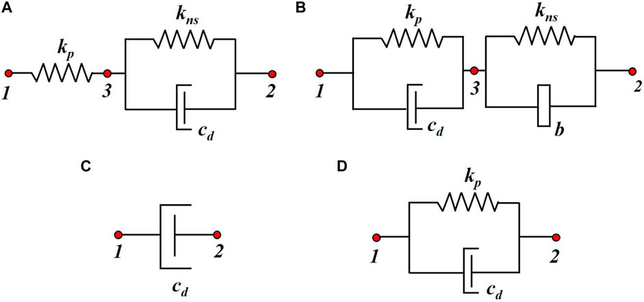
FIGURE 1. Mechanical model of supplemental dampers (A) NSD (B) NSID (C) VD (D) VED.
The supplemental dampers represented in Figure 1 are implemented to n-degree of freedom (DOF) structure (n denotes the number of the storey). The schematic representation of the n-DOF system with supplemental dampers is given in Figure 2. For any ith storey subjected to ground motion
where
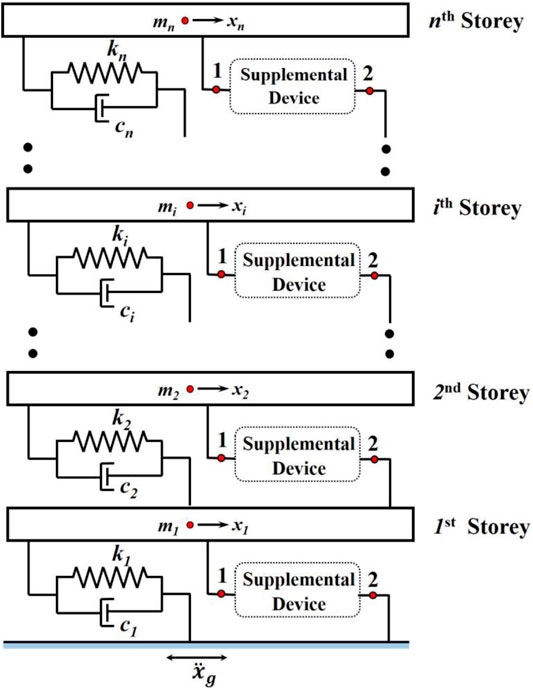
FIGURE 2. MDOF structure with supplemental dampers.
The damping force for different damping devices has the following expressions:
For NSD, we have
where
For NSID, we have
where
For a VD, we have
For a VED, we have
When introducing nd number of damping devices into the n-DOF structure, the equations of motion can be expressed into the compact matrix form:
where
For instance, a 4-DOF system with four supplemental dampers at each storey level,
When NSIDs are used as supplemental devices, the equation of motion is modified, and the structural mass matrix, damping matrix, and stiffness matrix are rewritten in the following format:
where
Defining
where
Optimization of NSID Parameters
The goal of an optimal design is to reduce or maximize an objective or multiple objectives. For the optimization problems concerned with the supplemental damping, the objective is to minimize the maximum storey acceleration and inter-storey drifts. Thus, the control problem reduces to a minimax optimization problem. For the current study, the design variables are the various non-dimensional parameters of the NSID, which are defined as follows:
Here,
Here,
Effective Damping and Frequencies of MDOF Structure With the NSID
Mathematically, eigenvalues define the physical characteristics of a system. For a dynamic system, eigenvalues are the roots of the characteristic equation. When the governing equation of motion is written in the state-space form (as described in the previous section), the state matrix
where
The circular modal frequencies (
As an example, the 20-storey benchmark structure (Spencer et al., 1998) is used to show the influence of the NSID on

TABLE 1. Parameters for the 20-storey benchmark shear building model.
Consider the 20-storey benchmark shear model equipped with the NSID at each floor level. Using Eqs 15 and 16 fundamental effective damping ratios (
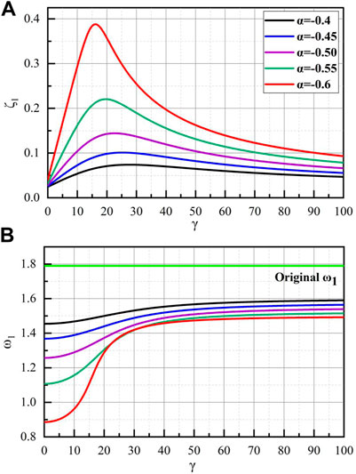
FIGURE 3. Effect of the NSID negative stiffness ratio (α) on fundamental mode (A) Effective damping ratios (B) Effective Frequencies.
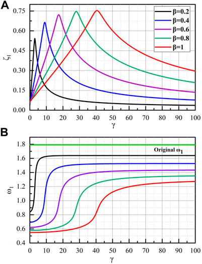
FIGURE 4. Effect of the NSID Positive stiffness ratio (β) on fundamental mode (A) Effective damping ratios (B) Effective Frequencies.
For the MDOF structure, the lower modes contribute a major part of the displacement response, while higher modes always influence the acceleration response of the system. Thus, it becomes imperative to study the effect of the NSID on the different modes of the benchmark shear building. Figure 5 presents the NSID influence on the first three modes of the benchmark model. The higher mode damping ratio curves are also bell-shaped. The damping parameter
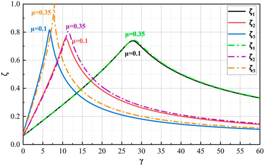
FIGURE 5. Modal damping curves with different mass ratios of NSID.
Optimization Procedure for NSID
An NSID consists of four parameters:
1) Select a minimum possible value of
2) Determine the modified structural matrices
3) Run the eigenvalue analysis for the system matrix
4) If modal frequency values are largely separated, increase the value of
5) Repeat steps 2,3, and 4 till the modal frequency values are in a close range.
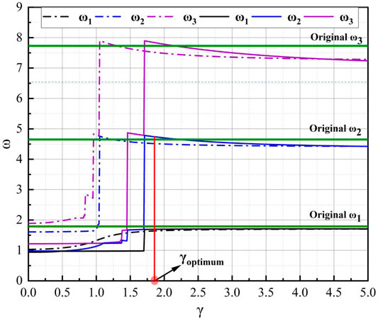
FIGURE 6. Effect of the NSID mass ratio (μ) on Modal Frequencies (μ = 0.25 for dashed lines and 0.7 for solid lines).
Seismic Response Evaluation of the 20-Storey Benchmark Building
This section presents the performance of the proposed NSID as a supplemental damping device (or energy dissipation device). The 20-storey benchmark building defined by Spencer et al. (1998) and simplified as a shear model by Wang et al. (2009) is used for performance evaluation. Table 1 describes the parameters of this benchmark model. First three natural frequencies are 1.7898, 4.6498, and 7.728 rad/sec. The first two modal damping ratios are assumed to be 2%, and the rest are calculated using Rayleigh damping criteria. Two sets of real earthquake records, near-fault (NF) and far-field (FF) are selected to evaluate the effectiveness of the NSID as a potential supplemental damper to the benchmark building. Ground motions used in response history analysis are described in Tables 2, 3. The control objective of this study is to suppress both drift and floor acceleration of the MDOF structure.
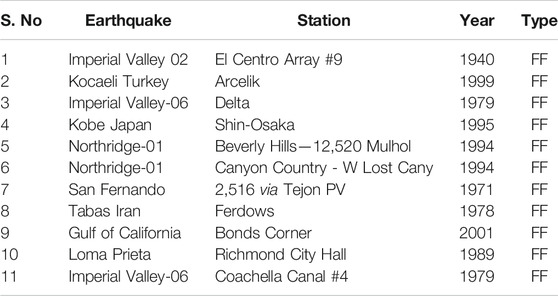
TABLE 2. A suite of FF real earthquake records.
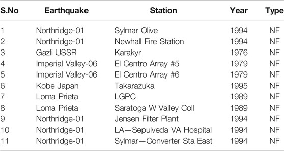
TABLE 3. A suite of NF real earthquake records.
The positive stiffness of the NSID at each storey level is given by
Time history plots are given in Figure 7 under Imperial Valley-02El Centro (FF) and Northridge-01 Sylmar Olive (NF). Figure 7 demonstrates the first storey drift of the benchmark structure under various supplemental dampers. Peak values of the drift are indicated for each supplemental damper. The drift of the system under the NSID as a supplemental damper has been effectively reduced. Similarly, Figure 8 depicts the time history for the top storey acceleration of the benchmark structure. These graphs illustrate that top-storey acceleration is likewise well-controlled.
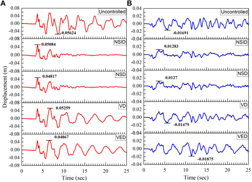
FIGURE 7. First Storey displacement time history (A) Northridge-NF (B) El Centro-FF.
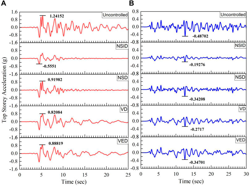
FIGURE 8. Top Storey acceleration time history (A) Northridge-NF (B) El Centro-FF.
Mean response envelopes for peak storey drifts and acceleration for the 20-storey benchmark building with different supplemental devices under FF and NF earthquakes are given in Figures 9, 10. The introduction of the VD reduces the uncontrolled structure’s peak storey drift and acceleration for both NF and FF excitations to some extent due to additional damping. In comparison with the VD, the application of the VED further reduces the peak inter-storey drift. However, VEDs enhance structural stiffness, which elevates structural modal frequencies. As a result, the earthquake force increases. The advantage of the reduced inter-storey drift by VED’s damping feature is lost because of increased acceleration values due to increased stiffness. Therefore, VED reduces acceleration to a less extent than VDs. In contrast with the VED and VD, the NSD reduces both the acceleration response and inter-storey drift for both NF and FF motions. These results can be attributed to the noticeable damping magnification effect, which offsets the disadvantage of reducing stiffness. The performance of the NSD is highly improved by the NSID as a control device under both NF and FF motions, especially in controlling the acceleration response. NSID uses the combined negative stiffness effect of the inerter and negative spring to reduce stiffness and modal frequencies. Also, combining the VED to an inerter and negative stiffness assembly reduces the disadvantage of VEDs. This enhances the damping behavior, and hence, better response control is achieved. Figures 9, 10 demonstrate that the NSID controls the acceleration response substantially, but lower storeys (1–5) show an average reduction in the drift. The efficiency of drift reduction increases from the 6th storey onwards. This observation is also noticed in time history plots. The possible reason is the lowering of lateral stiffness of the system.
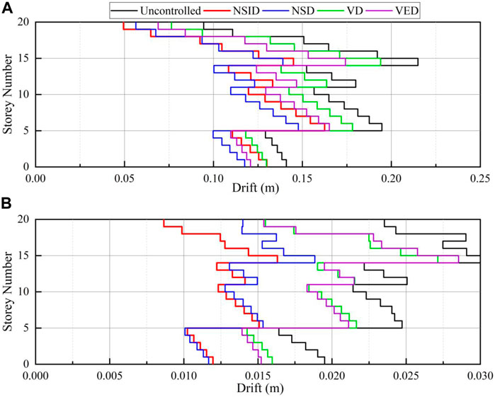
FIGURE 9. Mean Storey drift envelope (A) Near-Fault (B) Far-Field.
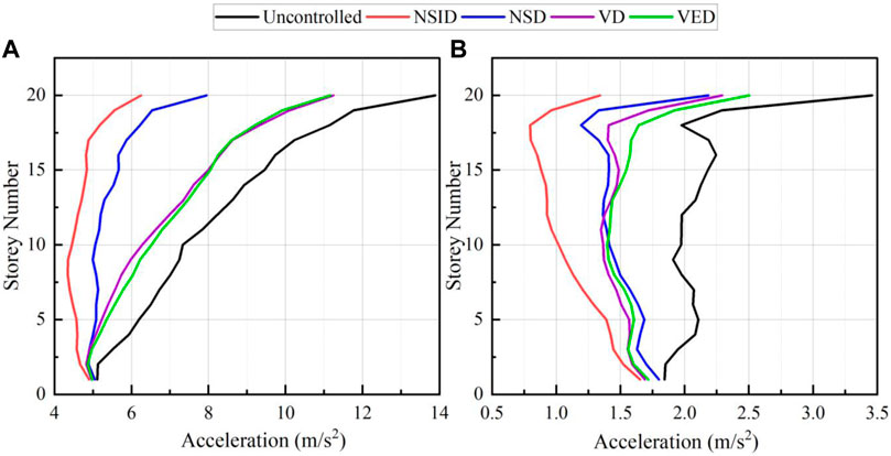
FIGURE 10. Mean Storey acceleration envelope (A) Near-Fault (B) Far-Field.
Discussion of Results for Partially Arranged NSIDs
The previous section shows the effectiveness of the NSID as a potential supplemental damper. An optimal NSID controls both objective variables of storey acceleration and the inter-storey drift. Due to the various considerations, uniform damper placement throughout the building may not be the case. Therefore, the performance of partially arranged NSIDs throughout the benchmark structure is evaluated in this section. The case of uniform distribution of NSIDs is referred to as Design I. In addition, two partial distributions of NSIDs are considered as Design II (bottom to 10th storey) and Design III (11th to the top-level). Table 4 describes optimal parameters for three design cases. Figures 11, 12 present the seismic response envelopes of the three above discussed design cases.
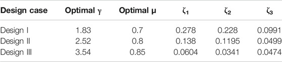
TABLE 4. Optimal parameters for the partial arrangement problem.
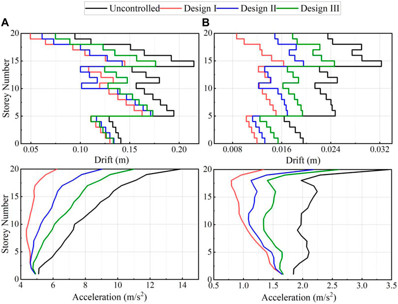
FIGURE 11. Mean response plots for three design cases (A) Near-Fault (B) Far-Field.

FIGURE 12. Mean shear envelope for three design cases (A) Near-Fault (B) Far-Field.
In terms of controlling both objective variables, Design I is ideal, followed by Design II. The influence of partially arranged NSIDs showcases an exciting feature. Partially placed NSIDs decrease the inter-storey drift marginally at the levels where NSIDs are implemented. However, an effective decrease in the drift of other storeys is achieved where no dampers are used. This feature is more pronounced in the storey shear distribution given in Figure 12. In particular, at the 10th storey level, a sudden decrease in the drift and corresponding shear is noticed for Design II. In other words, storeys, where NSID is introduced, concentrate the seismic deformation while other storeys are protected.
Therefore, the NSID is best introduced at storeys with relatively more minor inter-storey drift responses. In this way, the seismic-excited deformation will be concentrated mainly in these storeys. The performance of other storeys without NSIDs that have more significant drifts will be effectively improved. For the uncontrolled 20-storey benchmark structure, the maximum inter-storey drift occurs at the upper storeys (10th to 20th storeys shown in Figure 11). Therefore, NSIDs, when implemented at lower levels, generally perform better than NSIDs placed at higher storeys, reducing the maximum inter-storey drift. This inter-storey drift control is directly translated into storey shear control, as shown in Figure 12.
Conclusion
This research aims to improve the energy dissipation capacity of VDs and VEDs by combining negative stiffness and an inerter damper. NSDs have demonstrated the ability to improve the seismic performance in both NF and FF motions. The simultaneous use of negative stiffness and inerter elements has been proposed as NSIDs to improve NSDs. A simple optimization procedure has been put forward that considers the effect on modal frequencies and modal damping. Significant findings of this study are summarized as follows:
1) Traditional supplemental dampers, such as VD and VEDs, have quite drawbacks. The structural stiffness and thus the earthquake forces are increased by using these types of dampers.
2) The NSD and NSID are used in place of the traditional dampers, and they prove to be superior alternatives. The energy dissipation capacity of VDs and VEDs is improved by the synergy of negative stiffness and inerter elements. As a result of using the dashpot’s minimum damping co-efficient, a better seismic response can be obtained.
3) The inter-storey drifts and structural acceleration responses under FF and NF earthquakes are controlled by the proposed optimal design method for NSID as a supplemental damper.
4) NSID proposed in this study reduces the modal frequencies and introduces the negative stiffness in a wide frequency range. This feature helps NSIDs to outperform NSDs in terms of storey acceleration control.
5) For the low value of the positive stiffness ratio β, it is possible to obtain the mass ratio μ where the modal frequencies of the supplemented system match the original frequencies of the uncontrolled system. This property can be utilized to improve drift control for a low value of the damping parameter γ.
6) For partially implemented NSIDs, it is recommended to introduce these at storeys with a relatively smaller drift. This will ensure drift control at the levels where no dampers are installed.
Data Availability Statement
The raw data supporting the conclusion of this article will be made available by the authors, without undue reservation.
Author Contributions
All authors listed have made a substantial, direct, and intellectual contribution to the work and approved it for publication.
Conflict of Interest
The authors declare that the research was conducted in the absence of any commercial or financial relationships that could be construed as a potential conflict of interest.
Publisher’s Note
All claims expressed in this article are solely those of the authors and do not necessarily represent those of their affiliated organizations, or those of the publisher, the editors, and the reviewers. Any product that may be evaluated in this article, or claim that may be made by its manufacturer, is not guaranteed or endorsed by the publisher.
References
Attary, N., Symans, M., Nagarajaiah, S., Reinhorn, A. M., Constantinou, M. C., Sarlis, A. A., et al. (2015b). Performance Evaluation of Negative Stiffness Devices for Seismic Response Control of Bridge Structures via Experimental Shake Table Tests. J. Earthquake Eng. 19, 249–276. doi:10.1080/13632469.2014.962672
Attary, N., Symans, M., Nagarajaiah, S., Reinhorn, A. M., Constantinou, M. C., Sarlis, A. A., et al. (2015a). Experimental Shake Table Testing of an Adaptive Passive Negative Stiffness Device within a Highway Bridge Model. Earthquake Spectra 31, 2163–2194. doi:10.1193/101913EQS273M
Aydin, E., Öztürk, B., and Dutkiewicz, M. (2019). Analysis of Efficiency of Passive Dampers in Multistorey Buildings. J. Sound Vibration 439, 17–28. doi:10.1016/j.jsv.2018.09.031
Baker, J. W. (2007). “Measuring Bias in Structural Response Caused by Ground Motion Scaling,” in 8th Pacific Conf. Earthq. Eng., 1–6. doi:10.1002/eqe
Balaji, P. S., and Karthik SelvaKumar, K. (2021). Applications of Nonlinearity in Passive Vibration Control: A Review. J. Vib. Eng. Technol. 9, 183–213. doi:10.1007/s42417-020-00216-3
Basili, M., Angelis, M. D., and Pietrosanti, D. (2017). Dynamic Response of a Viscously Damped Two Adjacent Degree of freedom System Linked by Inerter Subjected to Base Harmonic Excitation. Proced. Eng. 199, 1586–1591. doi:10.1016/j.proeng.2017.09.062
Basu, B., Bursi, O. S., Casciati, F., Casciati, S., Del Grosso, A. E., Domaneschi, M., et al. (2014). A European Association for the Control of Structures Joint Perspective. Recent Studies in Civil Structural Control across Europe. Struct. Control. Health Monit. 21, 1414–1436. doi:10.1002/stc.1652
Bhaskararao, A. V., and Jangid, R. S. (2007). Optimum Viscous Damper for Connecting Adjacent SDOF Structures for Harmonic and Stationary white-noise Random Excitations. Earthquake Engng Struct. Dyn. 36, 563–571. doi:10.1002/EQE.636
Brzeski, P., Pavlovskaia, E., Kapitaniak, T., and Perlikowski, P. (2015). The Application of Inerter in Tuned Mass Absorber. Int. J. Non-Linear Mech. 70, 20–29. doi:10.1016/j.ijnonlinmec.2014.10.013
Buckle, I. G., and Mayes, R. L. (1990). Seismic Isolation: History, Application, and Performance-A World View. Earthquake Spectra 6, 161–201. doi:10.1193/1.1585564
Buckle, I. G. (2000). Passive Control of Structures for Seismic Loads. Bnzsee 33, 209–221. doi:10.5459/bnzsee.33.3.209-221
Chen, L., Nagarajaiah, S., and Sun, L. (2021). A Unified Analysis of Negative Stiffness Dampers and Inerter-Based Absorbers for Multimode cable Vibration Control. J. Sound Vibration 494, 115814. doi:10.1016/j.jsv.2020.115814
Chen, M., Papageorgiou, C., Scheibe, F., Wang, F.-c., and Smith, M. (2009). The Missing Mechanical Circuit Element. IEEE Circuits Syst. Mag. 9, 10–26. doi:10.1109/MCAS.2008.931738
Chen, M. Z. Q., Hu, Y., Huang, L., and Chen, G. (2014). Influence of Inerter on Natural Frequencies of Vibration Systems. J. Sound Vibration 333, 1874–1887. doi:10.1016/j.jsv.2013.11.025
Chen, M. Z. Q., and Hu, Y. (2019). Inerter and its Application in Vibration Control Systems. Singapore: Springer. doi:10.1007/978-981-10-7089-1
Cheng, F., Jiang, H., and Lou, H. (2008). Smart Structures: Innovative Systems for Seismic Response Control. 672. Available at: http://www.crcnetbase.com/doi/book/10.1201/9781420008173.
Connor, J., and Laflamme, S. (2014). Structural Motion Engineering. Springer. doi:10.1007/978-3-319-06281-5
Constantinou, M., Soong, T., and Dargush, G. (1998). Passive Energy Dissipation Systems for Structural Design and Retrofit. Multidiscip. Cent. Earthq. Eng. Res, 320. Available at: https://www.researchgate.net/profile/Michael-Constantinou/publication/265528194_Passive_Energy_Dissipation_Systems_for_Structural_Design_and_Retrofit_Monograph_No_1/links/555f886f08ae8c0cab30b3a0/Passive-Energy-Dissipation-Systems-for-Structural-Design-an (Accessed September 10, 2021).
De Domenico, D., and Ricciardi, G. (2018). Optimal Design and Seismic Performance of Tuned Mass Damper Inerter (TMDI) for Structures with Nonlinear Base Isolation Systems. Earthquake Engng Struct. Dyn. 47, 2539–2560. doi:10.1002/EQE.3098
Gao, H., Wang, H., Li, J., Wang, Z., Liang, R., Xu, Z., et al. (2021). Optimum Design of Viscous Inerter Damper Targeting Multi-Mode Vibration Mitigation of Stay Cables. Eng. Structures 226, 111375. doi:10.1016/j.engstruct.2020.111375
Gluck, N., Reinhorn, A. M., Gluck, J., and Levy, R. (1996). Design of Supplemental Dampers for Control of Structures. J. Struct. Eng. 122, 1394–1399. doi:10.1061/(asce)0733-9445(1996)122:12(1394)
Gürgöze, M., and Müller, P. C. (1992). Optimal Positioning of Dampers in Multi-Body Systems. J. Sound Vibration 158, 517–530. doi:10.1016/0022-460X(92)90422-T
Housner, G. W., Bergman, L. A., Caughey, T. K., Chassiakos, A. G., Claus, R. O., Masri, S. F., et al. (1997). Structural Control: Past, Present, and Future. J. Eng. Mech. 123, 897–971. doi:10.1061/(asce)0733-9399(1997)123:9(897)
Hu, Y., Chen, M. Z. Q., Shu, Z., and Huang, L. (2015). Analysis and Optimisation for Inerter-Based Isolators via Fixed-point Theory and Algebraic Solution. J. Sound Vibration 346, 17–36. doi:10.1016/j.jsv.2015.02.041
Jadhav, P. A., and Shaikh, S. A. (2019). Optimization of Seismic Response of Steel Structure Using Negative Stiffness Damper. Int. J. Adv. Struct. Eng. 11, 351–360. doi:10.1007/s40091-019-00237-7
Jangid, R. S. (2021). Optimum Tuned Inerter Damper for Base-Isolated Structures. J. Vib. Eng. Technol. 9, 1483–1497. doi:10.1007/s42417-021-00309-7
Jiang, Y., Zhao, Z., Zhang, R., De Domenico, D., and Pan, C. (2020). Optimal Design Based on Analytical Solution for Storage Tank with Inerter Isolation System. Soil Dyn. Earthquake Eng. 129, 105924. doi:10.1016/j.soildyn.2019.105924
Kelly, J. M. (1986). Aseismic Base Isolation: Review and Bibliography. Soil Dyn. Earthquake Eng. 5, 202–216. doi:10.1016/0267-7261(86)90006-0
Lavan, O., and Dargush, G. F. (2009). Multi-objective Evolutionary Seismic Design with Passive Energy Dissipation Systems. J. Earthquake Eng. 13, 758–790. doi:10.1080/13632460802598545
Lazar, I. F., Neild, S. A., and Wagg, D. J. (2014). Using an Inerter-Based Device for Structural Vibration Suppression. Earthquake Engng Struct. Dyn. 43, 1129–1147. doi:10.1002/eqe.2390
Li, H., Li, Y., and Li, J. (2020). Negative Stiffness Devices for Vibration Isolation Applications: A Review. Adv. Struct. Eng. 23, 1739–1755. doi:10.1177/1369433219900311
Li, Y., Li, S., and Chen, Z. (2021). Optimal Design and Effectiveness Evaluation for Inerter-Based Devices on Mitigating Seismic Responses of Base Isolated Structures. Earthq. Eng. Eng. Vib. 20, 1021–1032. doi:10.1007/s11803-021-2066-z
Loh, C.-H., Lin, P.-Y., and Chung, N.-H. (2000). Design of Dampers for Structures Based on Optimal Control Theory. Earthquake Engng. Struct. Dyn. 29, 1307–1323. doi:10.1002/1096-9845(200009)29:9<1307:aid-eqe972>3.0.co;2-d
Losanno, D., Londono, J. M., Zinno, S., and Serino, G. (2018). Effective Damping and Frequencies of Viscous Damper Braced Structures Considering the Supports Flexibility. Comput. Structures 207, 121–131. doi:10.1016/j.compstruc.2017.07.022
Luo, H., Zhang, R., and Weng, D. (2016). Mitigation of Liquid Sloshing in Storage Tanks by Using a Hybrid Control Method. Soil Dyn. Earthquake Eng. 90, 183–195. doi:10.1016/j.soildyn.2016.08.037
Ma, R., Bi, K., and Hao, H. (2020). Heave Motion Mitigation of Semi-submersible Platform Using Inerter-Based Vibration Isolation System (IVIS). Eng. Structures 219, 110833. doi:10.1016/j.engstruct.2020.110833
Ma, R., Bi, K., and Hao, H. (2021). Inerter-based Structural Vibration Control: A State-Of-The-Art Review. Eng. Structures 243, 112655. doi:10.1016/j.engstruct.2021.112655
Marian, L., and Giaralis, A. (2014). Optimal Design of a Novel Tuned Mass-Damper-Inerter (TMDI) Passive Vibration Control Configuration for Stochastically Support-Excited Structural Systems. Probabilistic Eng. Mech. 38, 156–164. doi:10.1016/j.probengmech.2014.03.007
Mathew, G. M., and Jangid, R. S. (2018). Seismic Response Control of a Building by Negative Stiffness Devices. Asian J. Civ. Eng. 19, 849–866. doi:10.1007/s42107-018-0068-6
Movaffaghi, H., and Friberg, O. (2006). Optimal Placement of Dampers in Structures Using Genetic Algorithm. Eng. Computations 23, 597–606. doi:10.1108/02644400610680324
Murakami, Y., Noshi, K., Fujita, K., Tsuji, M., and Takewaki, I. (2013). Simultaneous Optimal Damper Placement Using Oil, Hysteretic and Inertial Mass Dampers. Earthquakes and Structures 5, 261–276. doi:10.12989/eas.2013.5.3.261
Nagarajaiah, S., Reinhorn, A. M., Constantinou, M. C., Taylor, D. P., Pasala, D. T. R., and Sarlis, A. A. (2010). “True Adaptive Negative Stiffness: A New Structural Modification Approach for Seismic protection,” in 5th World Conf. Struct. Control Monit, 1–15.
Nyangi, P., and Ye, K. (2021). Optimal Design of Dual Isolated Structure with Supplemental Tuned Inerter Damper Based on Performance Requirements. Soil Dyn. Earthquake Eng. 149, 106830. doi:10.1016/j.soildyn.2021.106830
Ozturk, B., Cetin, H., and Aydin, E. (2017). Optimal Damper Allocation in Shear Buildings with Tuned Mass Dampers and Viscous Dampers. Ijeie 2, 89–120. doi:10.1504/ijeie.2017.10010008
Pasala, D. T. R., Sarlis, A. A., Nagarajaiah, S., Reinhorn, A. M., Constantinou, M. C., and Taylor, D. (2013). Adaptive Negative Stiffness: New Structural Modification Approach for Seismic protection. J. Struct. Eng. 139, 1112–1123. doi:10.1061/(ASCE)ST.1943-541X.0000615
Pasala, D. T. R., Sarlis, A. A., Reinhorn, A. M., Nagarajaiah, S., Constantinou, M. C., and Taylor, D. (2014). Simulated Bilinear-Elastic Behavior in a SDOF Elastic Structure Using Negative Stiffness Device: Experimental and Analytical Study. J. Struct. Eng. 140, 1–13. doi:10.1061/(ASCE)ST.1943-541X.0000830
Patel, C. C., and Jangid, R. S. (2014). Dynamic Response of Identical Adjacent Structures Connected by Viscous Damper. Struct. Control. Health Monit. 21, 205–224. doi:10.1002/stc.1566
Pietrosanti, D., De Angelis, M., and Giaralis, A. (2021). Experimental Seismic Performance Assessment and Numerical Modelling of Nonlinear Inerter Vibration Absorber (IVA)‐equipped Base Isolated Structures Tested on Shaking Table. Earthquake Engng Struct. Dyn. 50, 2732–2753. doi:10.1002/eqe.3469
Saaed, T. E., Nikolakopoulos, G., Jonasson, J.-E., and Hedlund, H. (2015). A State-Of-The-Art Review of Structural Control Systems. J. Vibration Control. 21, 919–937. doi:10.1177/1077546313478294
Sarlis, A. A., Pasala, D. T. R., Constantinou, M. C., Reinhorn, A. M., Nagarajaiah, S., and Taylor, D. P. (2013). Negative Stiffness Device for Seismic protection of Structures. J. Struct. Eng. 139, 1124–1133. doi:10.1061/(ASCE)ST.1943-541X.0000616
Sarlis, A. A., Pasala, D. T. R., Constantinou, M. C., Reinhorn, A. M., Nagarajaiah, S., and Taylor, D. P. (2016). Negative Stiffness Device for Seismic protection of Structures: Shake Table Testing of a Seismically Isolated Structure. J. Struct. Eng. 142, 1–13. doi:10.1061/(ASCE)ST.1943-541X.0001455
Shi, X., and Zhu, S. (2019). A Comparative Study of Vibration Isolation Performance Using Negative Stiffness and Inerter Dampers. J. Franklin Inst. 356, 7922–7946. doi:10.1016/j.jfranklin.2019.02.040
Silvestri, S., Gasparini, G., and Trombetti, T. (2011). Seismic Design of a Precast r.C. Structure Equipped with Viscous Dampers. Earthquakes and Structures 2, 297–321. doi:10.12989/EAS.2011.2.3.297
Silvestri, S., and Trombetti, T. (2007). Physical and Numerical Approaches for the Optimal Insertion of Seismic Viscous Dampers in Shear-type Structures. J. Earthquake Eng. 11, 787–828. doi:10.1080/13632460601034155
Singh, M. P., and Moreschi, L. M. (2002). Optimal Placement of Dampers for Passive Response Control. Earthquake Engng. Struct. Dyn. 31, 955–976. doi:10.1002/eqe.132
Singh, M. P., and Moreschi, L. M. (2001). Optimal Seismic Response Control with Dampers. Earthquake Engng. Struct. Dyn. 30, 553–572. doi:10.1002/eqe.23
Smith, M. C. (2002). Synthesis of Mechanical Networks: The Inerter. IEEE Trans. Automat. Contr. 47, 1648–1662. doi:10.1109/TAC.2002.803532
Smith, M. C. (2020). The Inerter: A Retrospective. Annu. Rev. Control. Robot. Auton. Syst. 3, 361–391. doi:10.1146/annurev-control-053018-023917
Smith, M. C., and Wang, F.-C. (2004). Performance Benefits in Passive Vehicle Suspensions Employing Inerters. Vehicle Syst. Dyn. 42, 235–257. doi:10.1080/00423110412331289871
Spencer, B. F., Christenson, R. E., and Dyke, S. J. (1998). Next Generation Benchmark Control Problem for Seismically Excited Buildings. In 2nd World Conf. Struct. Control. 1135–1360. Available at: http://nees.org/resources/2405/download/Report_bldg_full2.pdf.
Spencer, B. F., and Nagarajaiah, S. (2003). State of the Art of Structural Control. J. Struct. Eng. 129, 845–856. doi:10.1061/(asce)0733-9445(2003)129:7(845)
Symans, M. D., Charney, F. A., Whittaker, A. S., Constantinou, M. C., Kircher, C. A., Johnson, M. W., et al. (2008). Energy Dissipation Systems for Seismic Applications: Current Practice and Recent Developments. J. Struct. Eng. 134, 3–21. doi:10.1061/(asce)0733-9445(2008)134:1(3)
Taflanidis, A. A., Giaralis, A., and Patsialis, D. (2019). Multi-objective Optimal Design of Inerter-Based Vibration Absorbers for Earthquake protection of Multi-Storey Building Structures. J. Franklin Inst. 356, 7754–7784. doi:10.1016/j.jfranklin.2019.02.022
Takewaki, I., Fujita, K., Yamamoto, K., and Takabatake, H. (2011). Smart Passive Damper Control for Greater Building Earthquake Resilience in Sustainable Cities. Sustain. Cities Soc. 1, 3–15. doi:10.1016/j.scs.2010.08.002
Takewaki, I., Murakami, S., Yoshitomi, S., and Tsuji, M. (2012). Fundamental Mechanism of Earthquake Response Reduction in Building Structures with Inertial Dampers. Struct. Control. Health Monit. 19, 590–608. doi:10.1002/stc.457
Takewaki, I. (1997). Optimal Damper Placement for Minimum Transfer Functions. Earthquake Engng. Struct. Dyn. 26, 1113–1124. doi:10.1002/(sici)1096-9845(199711)26:11<1113:aid-eqe696>3.0.co;2-x
Talley, P. C., Javidialesaadi, A., Wierschem, N. E., and Denavit, M. D. (2021). Evaluation of Steel Building Structures with Inerter-Based Dampers under Seismic Loading. Eng. Structures 242, 112488. doi:10.1016/j.engstruct.2021.112488
Tiwari, N. D., Gogoi, A., Hazra, B., and Wang, Q. (2021). A Shape Memory alloy-tuned Mass Damper Inerter System for Passive Control of Linked-SDOF Structural Systems under Seismic Excitation. J. Sound Vibration 494, 115893. doi:10.1016/j.jsv.2020.115893
Tsai, H.-C., and Lin, G.-C. (1993). Optimum Tuned-Mass Dampers for Minimizing Steady-State Response of Support-Excited and Damped Systems. Earthquake Engng. Struct. Dyn. 22, 957–973. doi:10.1002/eqe.4290221104
Uemura, R., Akehashi, H., Fujita, K., and Takewaki, I. (2021). Global Simultaneous Optimization of Oil, Hysteretic and Inertial Dampers Using Real-Valued Genetic Algorithm and Local Search. Front. Built Environ. 7, 795577. doi:10.3389/fbuil.2021.795577
Wang, M., Sun, F.-F., Yang, J.-q., and Nagarajaiah, S. (2019b). Seismic protection of SDOF Systems with a Negative Stiffness Amplifying Damper. Eng. Structures 190, 128–141. doi:10.1016/j.engstruct.2019.03.110
Wang, M., Sun, F. f., and Nagarajaiah, S. (2019a). Simplified Optimal Design of MDOF Structures with Negative Stiffness Amplifying Dampers Based on Effective Damping. Struct. Des. Tall Spec. Build 28, 1–26. doi:10.1002/tal.1664
Wang, S., and Mahin, S. A. (2018). High-performance Computer-Aided Optimization of Viscous Dampers for Improving the Seismic Performance of a Tall Building. Soil Dyn. Earthquake Eng. 113, 454–461. doi:10.1016/j.soildyn.2018.06.008
Wang, Y., Lynch, J. P., and Law, K. H. (2009). Decentralized ℋþ∞controller Design for Large-Scale Civil Structures. Earthquake Engng Struct. Dyn. 38, 377–401. doi:10.1002/eqe.862
Wen, Y., Chen, Z., and Hua, X. (2017). Design and Evaluation of Tuned Inerter-Based Dampers for the Seismic Control of MDOF Structures. J. Struct. Eng. 143, 04016207. doi:10.1061/(ASCE)st.1943-541x.0001680
Whittle, J. K., Williams, M. S., Karavasilis, T. L., and Blakeborough, A. (2012). A Comparison of Viscous Damper Placement Methods for Improving Seismic Building Design. J. Earthquake Eng. 16, 540–560. doi:10.1080/13632469.2011.653864
Wongprasert, N., and Symans, M. D. (2004). Application of a Genetic Algorithm for Optimal Damper Distribution within the Nonlinear Seismic Benchmark Building. J. Eng. Mech. 130, 401–406. doi:10.1061/(asce)0733-9399(2004)130:4(401)
Zhang, R. H., and Soong, T. T. (1992). Seismic Design of Viscoelastic Dampers for Structural Applications. J. Struct. Eng. 118, 1375–1392. doi:10.1061/(asce)0733-9445(1992)118:5(1375)
Zhang, R., Zhao, Z., Pan, C., Ikago, K., and Xue, S. (2020). Damping Enhancement Principle of Inerter System. Struct. Control. Health Monit. 27, 1–21. doi:10.1002/stc.2523
Keywords: energy dissipation devices, inerters, negative stiffness dampers, seismic design, vibration control, benchmark structure
Citation: Islam NU and Jangid RS (2021) Seismic Performance of the Inerter and Negative Stiffness–Based Dampers for Vibration Control of Structures. Front. Built Environ. 7:773622. doi: 10.3389/fbuil.2021.773622
Received: 10 September 2021; Accepted: 02 December 2021;
Published: 22 December 2021.
Edited by:
Farhad Behnamfar, Isfahan University of Technology, IranCopyright © 2021 Islam and Jangid. This is an open-access article distributed under the terms of the Creative Commons Attribution License (CC BY). The use, distribution or reproduction in other forums is permitted, provided the original author(s) and the copyright owner(s) are credited and that the original publication in this journal is cited, in accordance with accepted academic practice. No use, distribution or reproduction is permitted which does not comply with these terms.
*Correspondence: Naqeeb Ul Islam, bmFxZWVidWxpc2xhbUBpaXRiLmFjLmlu