 Tomoya Nakamura
 Kohei Fujita
 Izuru Takewaki
- Department of Architecture and Architectural Engineering, Graduate School of Engineering, Kyoto University, Kyoto, Japan
We revisit a unique building system including a base-isolation, building-connection hybrid control system. The base-isolation system withstands pulse-type earthquake ground motions effectively and the building-connection system resists long-duration earthquake ground motions efficiently. A simple smart critical response evaluation method without nonlinear time-history response analysis is proposed for this hybrid building system under near-fault ground motions. An analytical expression of the maximum elastic-plastic deformation of a damped bilinear hysteretic single-degree-of-freedom (SDOF) model under critical double impulse as a representative of pulse-type ground motions derived in our previous paper plays an important role in the development of the simple critical response evaluation method. A two-step transformation procedure into an SDOF model is proposed. The first step is the transformation of the main base-isolated building into an SDOF system and the second step is the reduction of the connecting dampers supported on a sub building to a damper with a sophisticated compensation factor on an assumed rigid wall. The evaluation of damping coefficients with the consideration of yielding of the base-isolation story is a key step in this paper. Different from the previous work, the equivalent damping coefficient is derived depending on the response range before and after yielding of the base-isolation story. This treatment enhances the accuracy of the proposed method. The accuracy and reliability of the proposed response evaluation method is demonstrated by the time-history response analysis of the multi-degree-of-freedom (MDOF) model.
1 Introduction
The resilience of building structures during and after natural disasters is a central theme of late, and many investigations have been accumulated (Bruneau and Reinhorn, 2006; Takewaki et al., 2012). Bruneau and Reinhorn (2006) introduced four factors (redundancy, robustness, rapidity, and resourcefulness) to characterize structure resilience. In earthquake-prone countries and regions, it is essential to design building structures so as to resist severe earthquakes without major damage that obstructs their continuing use (Amadio et al., 2003; Takewaki et al., 2012; Takewaki, 2013; Takewaki et al., 2013). Since intrinsically uncertain characteristics of earthquake ground motions are inevitable, the reliable prediction of forthcoming events in regards to time, space, and character is extremely difficult (Takewaki, 2013; Takewaki et al., 2011; Takewaki et al., 2012; Takewaki et al., 2013). Although newer buildings systems such as passive control systems and base-isolation systems are anticipated as effective strategies for guaranteeing the structural safety of building structures, the structural properties of constituent members and elements of such innovative systems are not certain (Ben-Haim, 2006; Fujita et al., 2021). In Japan, the consideration of the variabilities of structural properties of isolators and dampers is mandatory in the design of passively controlled buildings and base-isolated buildings because the uncertainty degree (
Since the 1980s, base-isolated buildings have been developed rapidly. They are effective for pulse-type ground motions with predominant periods shorter than a few seconds or random earthquake ground motions (Hall et al., 1995; Jangid, 1995; Kelly, 1999; Naeim and Kelly, 1999; Jangid and Kelly, 2001; Hino et al., 2008; Takewaki and Fujita, 2009). However, their earthquake resilience is not completely guaranteed for long-period ground motions with a predominant period of 5–8 s (Kamae et al., 2004; Ariga et al., 2006). Although it is believed in general that passive energy dissipating systems (especially connected building systems) are effective for long-duration and long-period ground motions due to allowing sufficient time for energy dissipation (Luco and Barros, 1998; Basili and Angelis, 2007; Takewaki, 2007; Patel and Jangid, 2011; Takewaki et al., 2011; Takewaki et al., 2012; Richardson et al., 2013; Fukumoto and Takewaki, 2015; Kawai et al., 2021), they are not necessarily resilient against impulsive pulse-type ground motions.
In this paper, a new kind of hybrid or dual passive control building systems is treated in which a base-isolated building model is supported by a sub building (e.g., car parking tower) through oil dampers (Murase et al., 2013; Kasagi et al., 2016; Fukumoto and Takewaki 2017). Some researchers demonstrated that this new passive control system is effectively robust for two counterpart-type earthquake ground motions, i.e., pulse-type ground motions and long-duration, long-period ground motions (Murase et al., 2013; Kasagi et al., 2016; Fukumoto and Takewaki 2017). It has also been demonstrated through the input energy analysis in the frequency domain that, although the connecting oil dampers do not withstand pulse-type ground motions effectively due to the lack of time for energy dissipation, those dampers work smartly for long-duration, long-period ground motions (Taniguchi et al., 2016; Tamura et al., 2017). However, these analyses are limited to linear models. Although Hayashi (2018) and Hayashi et al. (2018) developed a simple method using a single-degree-of-freedom (SDOF) model for simulating the earthquake response of these buildings including the base-isolation, building connection hybrid damper system of nonlinear properties, the accuracy for near-fault ground motions is relatively low because of the non-robust evaluation of damping properties (Hayashi, 2018), or the method was applied only to the response under long-duration ground motion (Hayashi et al., 2018).
A simple and sophisticated response evaluation method using an SDOF model is proposed in this paper for the above-mentioned base-isolation, building-connection hybrid structural system under a near-fault ground motion. As in the previous method (Hayashi, 2018; Hayashi et al., 2018), a two-step transformation of the overall structural system into an SDOF model is conducted. The first step is the transformation into an SDOF system and the second step is the reduction of the connecting oil dampers supported on a sub building to upper-story concentrated oil dampers with a smart compensation factor on a rigid wall. It is shown that application of the previously derived analytical expression (Akehashi et al., 2018) of the maximum deformation to the reduced SDOF model under the critical double impulse as a representative of pulse-type near-fault ground motions enables the establishment of a simplified, but rather accurate response evaluation method.
2 Double Impulse as Representative of Near-Fault Ground Motion
2.1 Transformation of the Main Part of Near-Fault Ground Motion into Double Impulse
The concept of a pair of impulses with inverse directions to each other, called a double impulse, was introduced by Kojima and Takewaki (2015a) to represent a major part of near-fault ground motions. Since the characteristic main part of near-fault ground motions is well known to be expressed by a pulse-type one-cycle or 1.5-cycle sine wave and is influential particularly for tall and base-isolated buildings, with a rather long natural period (Sasani and Bertero, 2000; Mavroeidis and Papageorgiou, 2003; Makris and Black, 2004; Mavroeidis et al., 2004; Kalkan and Kunnath, 2006). Figure 1A shows an example of a near-fault ground motion (Rinaldi FN component during the 1994 Northridge earthquake) and its modeling into a one-cycle sine wave and a double impulse. Figure 1B illustrates the velocity and displacement properties of the one-cycle sine wave and the double impulse. The red arrows indicate the Dirac delta function
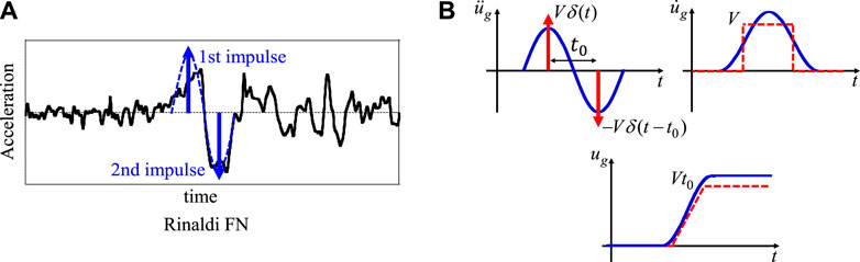
FIGURE 1. Transformation of recorded ground motion into a one-cycle sine wave and double impulse, (A) Example of Rinaldi Station FN component during 1994 Northridge earthquake and its modeling into a one-cycle sine wave and double impulse, (B) Velocity and displacement properties of a one-cycle sine wave and double impulse.
To make the double impulse a reliable substitute for near-fault ground motions, it is important to compare it with the one-cycle sine wave. The equivalent one-cycle sine wave with the circular frequency
where
3 Summary of Previous Research for Accuracy Upgrade
The base-isolation, building-connection hybrid control system as shown in Figure 2A was treated by Murase et al. (2013). They demonstrated the high performance of this control system for both impulsive and long-duration ground motions. Then, Hayashi (2018) tried to propose a simple response evaluation method using an SDOF model for impulsive and long-duration ground motions (Kojima and Takewaki, 2015b). It was shown that, while his simple model is effective for long-duration ground motions (Hayashi et al., 2018), it is not for impulsive ground motions resulting from the narrow-band estimation performance of the equivalent damping for a broader range of deformation including a plastic region. In this paper, a revised transformation method effective also for impulsive ground motions is presented. For this purpose, the method by Hayashi (2018) is explained first.
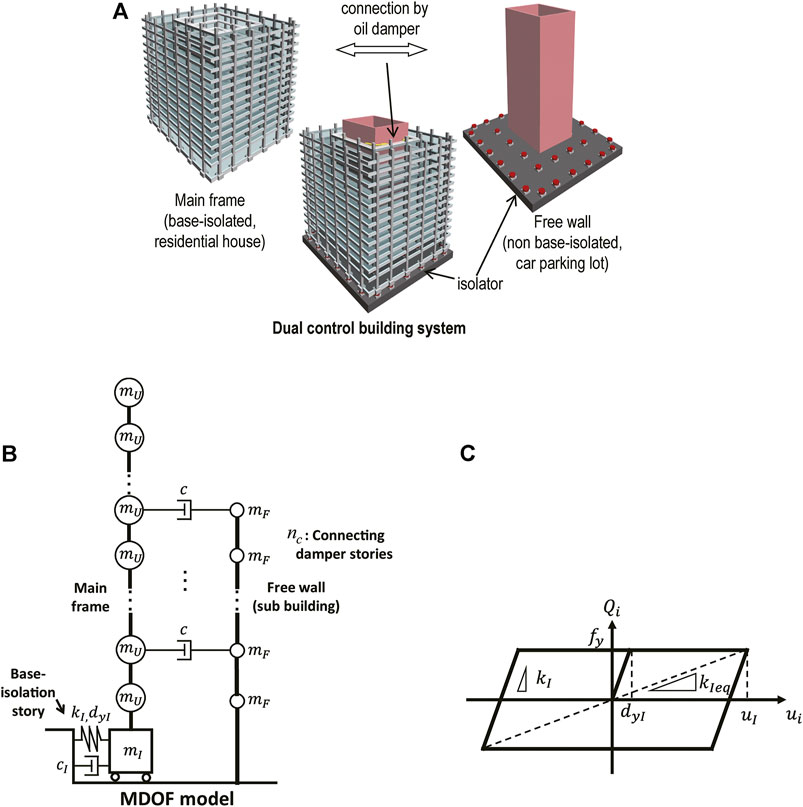
FIGURE 2. Base-isolation, building-connection hybrid control system, (A) Overview of system (Fukumoto and Takewaki, 2017), (B) MDOF shear building model with the base-isolation, building-connection hybrid control system, (C) Restoring force-deformation relation of the base-isolation story.
Consider a multi-degree-of-freedom (MDOF) shear building model with the base-isolation, building-connection hybrid control system as shown in Figure 2B. The common mass of the main building, the common mass of the sub building, and the mass of the base-isolation story are denoted by
In the method of Hayashi (2018), an elastic-perfectly plastic SDOF model with viscous damping was introduced to make use of an effective response evaluation method by the critical (resonant) double impulse (Kojima et al., 2018).
In the single base-isolated building, the superstructure is modeled into an SDOF model and a 2DOF model is constructed with the super building model mass
By applying the above-mentioned assumption, the mass of the SDOF model is obtained as
The series-spring assumption leads to the following initial stiffness of the SDOF model.
As for the damping, the series-spring assumption of complex springs provides the damping coefficient
where i is the imaginary unit and
From Eqs 5, 6,
The problem in deriving
The compensation coefficient
4 A Simple Critical Response Evaluation Method for Base-Isolated Building Under Double Impulse as Representative of Near-Fault Ground Motion
As explained before, it was shown that, while Hayashi’s simple model (Hayashi, 2018) is effective for long-duration ground motions (Hayashi et al., 2018), it is not for impulsive ground motions. In this paper, a revised transformation method effective for even impulsive ground motions is presented.
4.1 Plane Frame Model of Base-Isolated High-Rise Building
Consider a 40-story base-isolated frame building model as shown in Figure 3. Unlike the base-isolation system used in Section 3, lead rubber isolators and oil dampers are employed as the constituent members of the base-isolated story. The total depth of these isolators is 200 [mm]. This base-isolated frame building model is reduced to an SDOF mass-spring model with a dashpot via a 2DOF model as illustrated in Figure 3. For the simplicity of presentation of the proposed theory, the super building frame has a constant floor mass
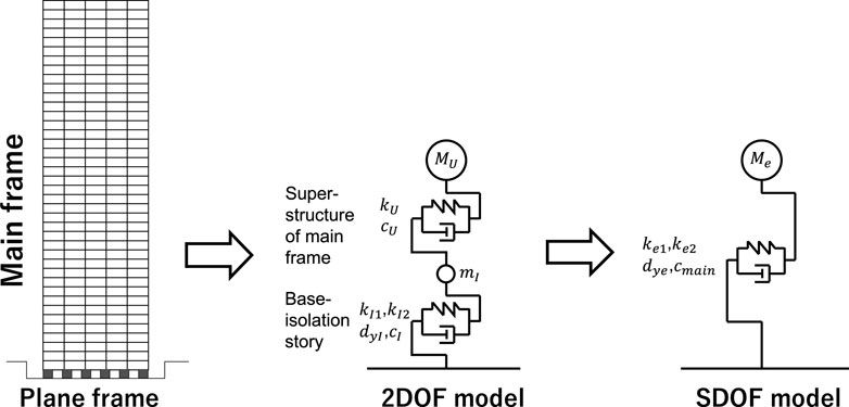
FIGURE 3. Reduction of base-isolated tall plane frame into SDOF model.
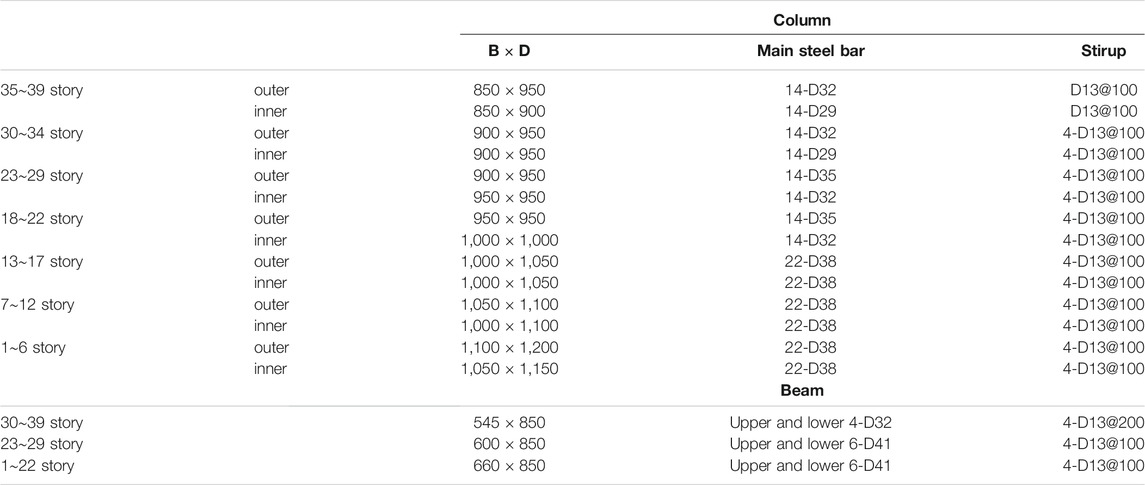
TABLE 1. Member parameters of plane frame.
4.2 Transformation of Base-Isolated Building Frame into SDOF Model
Consider the transformation of a base-isolated building frame into a 2DOF model.
Since the fundamental natural period of the super building with a fixed base is 3.0 (s), the stiffness of the super building can be obtained as
The initial stiffness
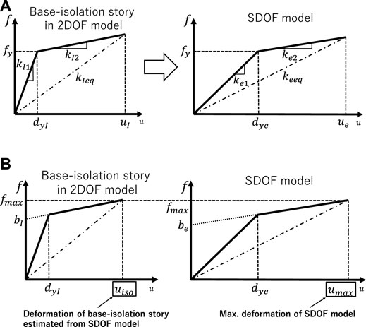
FIGURE 4. Transformation from 2DOF model into SDOF model, (A) Force-deformation relation of a base-isolation story in 2DOF model and that in SDOF model, (B) Evaluation of deformation of the base-isolation story in SDOF model.
The damping coefficient of the base-isolation story is determined by considering the number of oil dampers.
The 2DOF model set above is modeled into an SDOF model as shown in Figure 3. Since
The stiffness and damping coefficient of the SDOF model are determined differently in the elastic region and the plastic region of the base-isolation story. While Hayashi (2018) determined the equivalent damping coefficient only for the initial stiffness, that is determined differently in the elastic region and the plastic region of the base-isolation story.
In the region before the yielding of the base-isolation story, the equivalent stiffness
where
After the yielding of the steel damper in the base-isolation story, the stiffness reduces to
where n indicates the iteration cycle number. Based on these values, the equivalent stiffness and the equivalent damping coefficient of the SDOF model are obtained from
where
In Eq. 15,
Once
Through the above-mentioned procedure, the parameters
The maximum deformation of the bilinear hysteretic SDOF model to the critical double impulse was derived by Akehashi et al. (2018). In this paper, this closed-form expression is used. The relation between
where
In Eq. 14, the parameters of the SDOF model are determined for an assumed equivalent stiffness
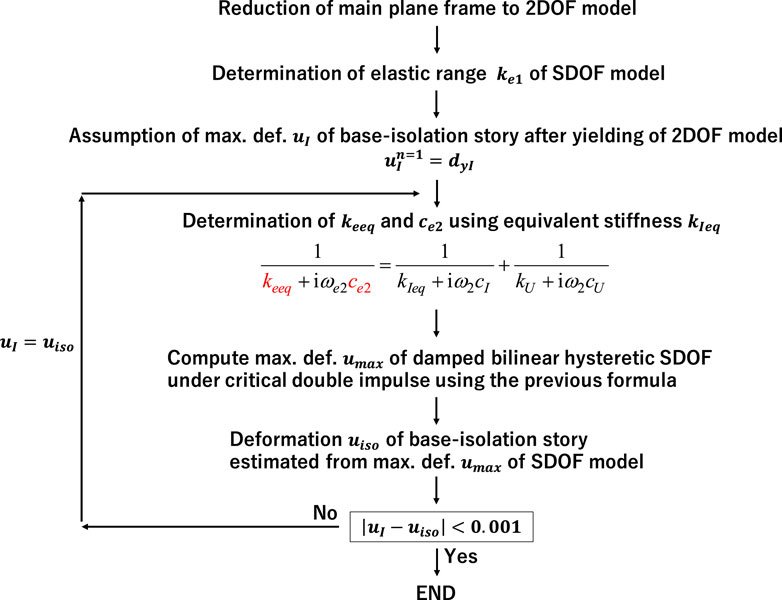
FIGURE 5. Flow for determining equivalent stiffness.
4.3 Accuracy Check of Proposed Simple Response Evaluation Method Using SDOF Model Through Comparison With Time-History Response Analysis Result for Plane Frame Model
The parameters of the 2DOF model and the SDOF model obtained by the above-mentioned procedure are shown in Table 2.
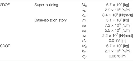
TABLE 2. Parameters of 2DOF model and SDOF model of base-isolated building.
Since the second stiffness
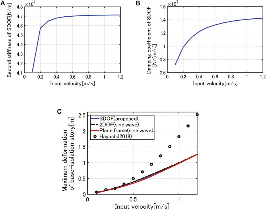
FIGURE 6. Parameters of reduced SDOF model with respect to input velocity level and accuracy check of proposed simple response evaluation method for SDOF model with respect to input velocity level, (A) Second-branch stiffness of SDOF model, (B) Damping coefficient, (C) Maximum deformation comparison of base-isolation story among proposed one, 2DOF model under one-cycle sine wave, plane frame under one-cycle sine wave and previous work by Hayashi (2018).
5 A Simple Critical Response Evaluation Method for Base-Isolation Building-Connection Hybrid System Under Double Impulse as Representative of Near-Fault Ground Motion
Consider a base-isolation, building-connection hybrid control system as shown in Figure 7. By extending the previous method by Hayashi (2018) to a more sophisticated method including an accurate damping evaluation, a more reliable response evaluation method for a simple SDOF model is presented. This method enables the evaluation of the maximum deformation of the base-isolation story under a double impulse as a representative of near-fault ground motions without laborious time-history response analysis.
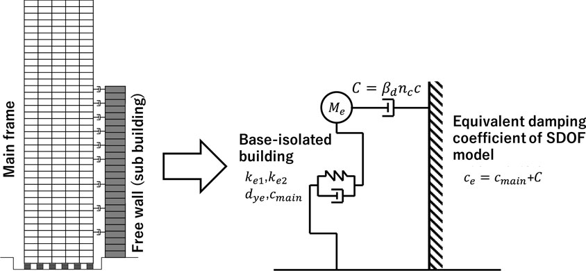
FIGURE 7. Plane frame including base-isolation building-connection hybrid control system and its reduction to SDOF model supported on rigid wall by compensated oil dampers.
5.1 Base-Isolation Building-Connection Hybrid System
The member parameters of this system are the same as those in Table 1. The connection dampers are placed on stories 4, 8, 12, 16, 18, 20, 22, 24, and 26. While Hayashi (2018) treated a shear building model, the present paper deals with a reinforced concrete plane frame. As in Section 4.1, the structural damping ratio of the super-structure (instantaneous stiffness-proportional damping) is set to 0.03. The strength of concrete is Fc60 (60 [N/mm2]) and the Young’s modulus is 33,500 [N/mm2]. In addition, the restoring-force characteristic of the base-isolation story is extended from the elastic-perfectly plastic model to the bilinear hysteretic model for the purpose of practicality.
5.2 Transformation of Base-Isolation Building-Connection Hybrid System into SDOF Model
The simplified SDOF model of a base-isolated building is further reduced to another SDOF model by connecting that SDOF model to a rigid wall as a representative of a stiff sub-building as shown in Figure 7. In this simplification procedure, a compensation coefficient
As in the method by Hayashi (2018), the RMDOF model with the compensation factor
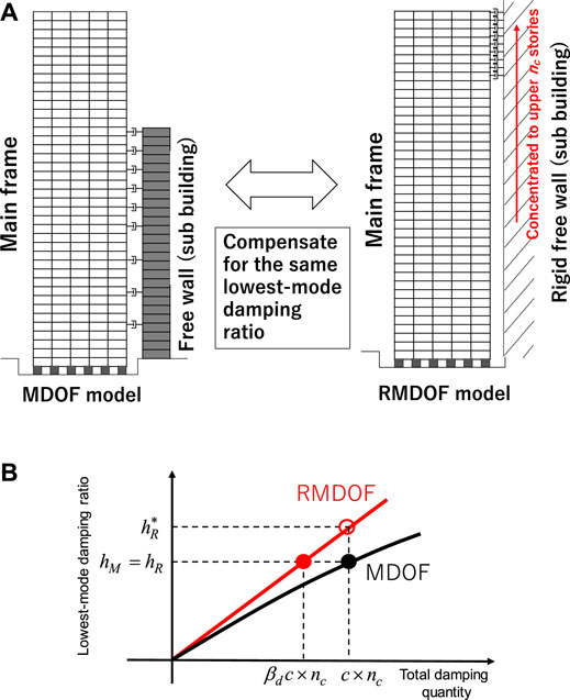
FIGURE 8. Introduction of RMDOF model and procedure for evaluating compensation factor
The compensation factor
Equation 19 requires repetition for obtaining
In the complex eigenvalue analysis, it is necessary to determine the equivalent stiffness of the base-isolation story. In this paper, the equivalent stiffness is to be obtained from the analysis for the SDOF model with
Figure 9A shows the relation of the lowest-mode damping ratio of the MDOF model and the RMDOF model with the equivalent stiffness of the base-isolation story where five damping coefficients of the connecting damper are taken. The following observation can be drawn from Figure 9A
*The lowest-mode damping ratio of the MDOF model exhibits different values depending on the equivalent stiffness. The variation is large in the range of smaller equivalent stiffness.
*The lowest-mode damping ratio of the RMDOF model indicates larger values than the MDOF model. The difference is larger in the range of larger equivalent stiffness.
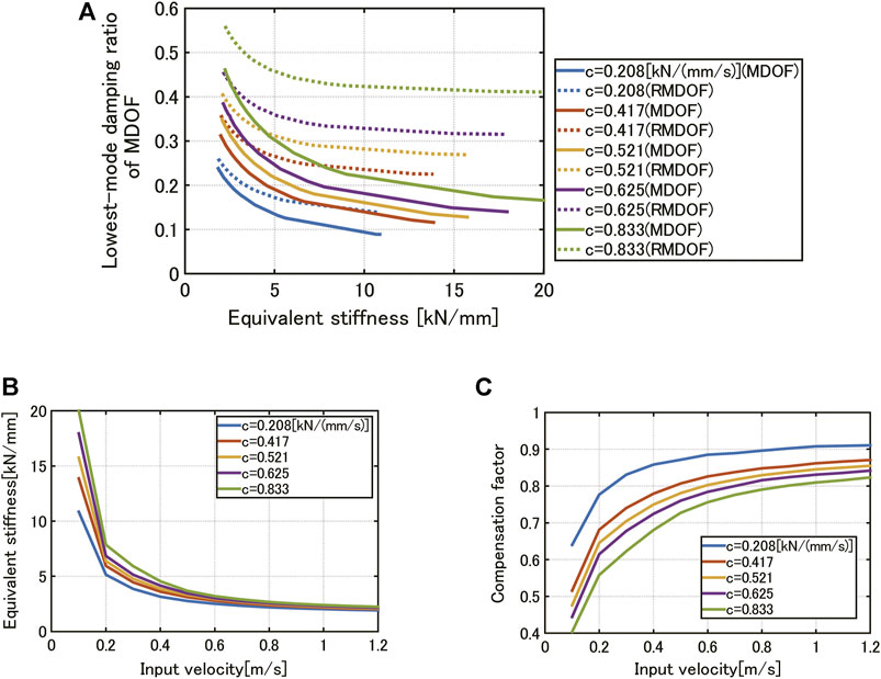
FIGURE 9. Evaluation of compensation factor, (A) Relation of lowest-mode damping ratio of MDOF model and RMDOF model with equivalent stiffness of base-isolation story where five damping coefficients of connecting damper, (B) Relation of equivalent stiffness of base-isolation story with input velocity level, (C) Relation of compensation factor with input velocity level.
Once such a relationship is obtained, the compensation factor
Figure 10 presents the comparison of the maximum deformation of the base-isolation story by the proposed method for the SDOF model (with and without compensation factor) with that by time-history response analysis for the plane frame model for various connection damper levels. It can be observed that, while the proposed method exhibits a good correspondence to the plane frame model regardless of the compensation factor
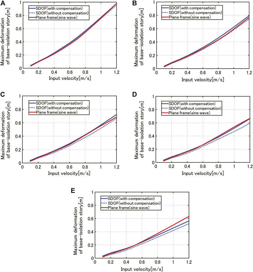
FIGURE 10. Comparison of the maximum deformation of the base-isolation story by the proposed method for the SDOF model (with and without compensation factor) with that by time-history response analysis for the plane frame model for various connection damper levels, (A)
6 Verification of Validity of Using One-Cycle Sine Wave Equivalent to Critical Double Impulse for SDOF Model as Critical Input for Plane Frame
In Sections 4, 5, the one-cycle sine wave equivalent to the critical double impulse for the SDOF model was used to verify the accuracy of the proposed response evaluation method. However, it seems necessary to check whether the critical double impulse for the SDOF model is actually critical for the plane frame model. In this section, this issue will be investigated.
6.1 Critical Double Impulse for Plane Frame
Recently, many multi-purpose structural analysis programs have become available. In this paper, a general-purpose structural analysis program SNAP (Kozo System Co., 2019) is used. In this program, the accuracy check is included automatically, e.g., the processing of unbalanced forces.
The double impulse
Kawai et al. (2021) showed that
Furthermore, Akehashi and Takewaki (2019) made clear that the critical input of the second impulse can be characterized by the criterion that the critical timing of the second impulse is the time of the zero story shear in the first story. For the present model, the following relation holds.
where
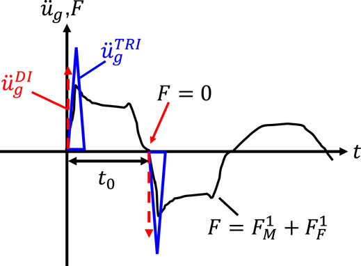
FIGURE 11. Critical timing of second impulse and simulation of impulse by one-point acceleration input.
6.2 Comparison of the Response of Plane Frame to One-Cycle Sine Wave With Response to Impulsive Acceleration Input
Figure 12A shows the comparison of the maximum deformation of the base-isolation story of the plane frame model under the one-cycle sine wave equivalent to the critical double impulse for the SDOF model with that under the critical double impulse (a pair of inverse-direction one-point acceleration inputs) for the plane frame model. The connection damping coefficient is given by
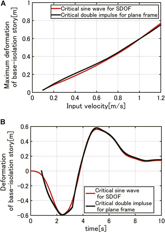
FIGURE 12. Comparison of deformation of the base-isolation story of plane frame model under one-cycle sine wave equivalent to the critical double impulse for SDOF model with that under critical double impulse (a pair of inverse-direction one-point acceleration inputs) for plane frame model, (A) Maximum deformation of base-isolation story, (B) Time history of deformation of the base-isolation story (input velocity level V = 1.0 [m/s]).
Figure 12B illustrates the time histories of the above-mentioned two inputs. The phases of the time histories are adjusted. It can be understood that the responses under both inputs coincide well and the simple response evaluation method proposed in the paper is reliable.
7 Investigation on Performance of Proposed Evaluation Method Through Time-History Response Analysis for Recorded Ground Motion
It seems important to demonstrate the applicability of the proposed simple response evaluation method to actual recorded ground motions.
Figure 13 shows the applicability of the proposed evaluation method to a recorded ground motion through the time-history response analysis (Rinaldi Station FN comp. during1994 Northridge). Figure 13A presents the recorded ground motion acceleration and the corresponding one-cycle sinusoidal wave where the acceleration amplitude and the period of the extracted one-cycle sinusoidal wave are 7.85 [m/s] and 0.8 [s]. As for connecting dampers, the damping coefficient c = 2.5 × 10⁶ [Ns/m] is used. The other parameters are the same as in the previous section. Figure 13B illustrates the maximum displacement of the SDOF model by the proposed method under the critical double impulse and by the time-history response analysis under the recorded ground motion. Since the amplitude and the period of the one-cycle sinusoidal wave are fixed, the model parameters
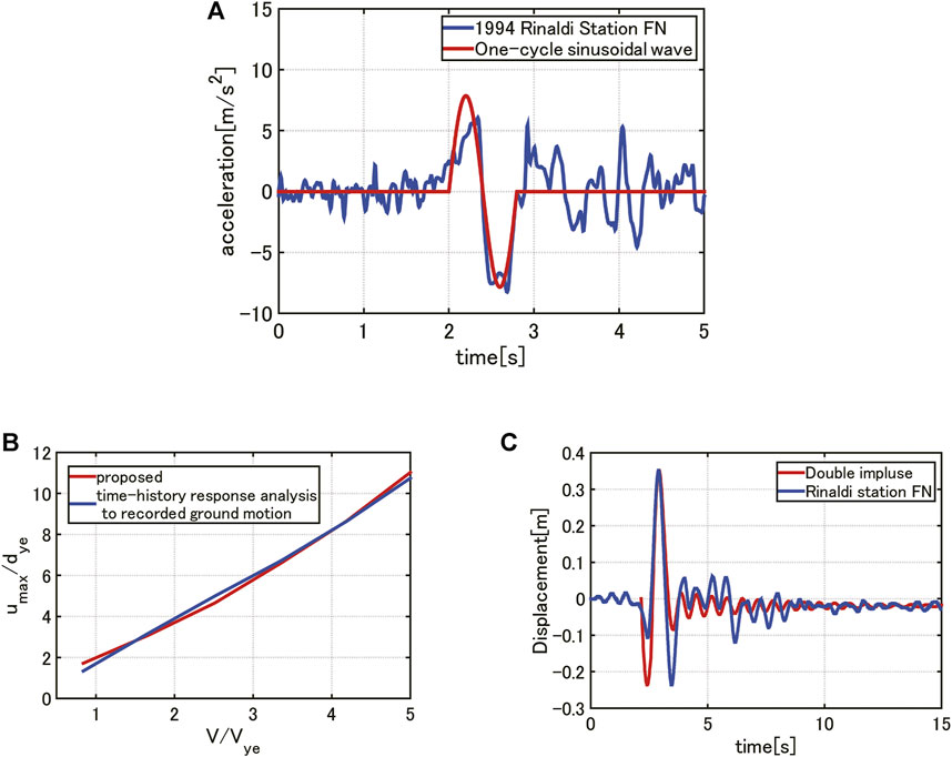
FIGURE 13. Comparison of proposed evaluation method with time-history response analysis for recorded ground motion, (A) Rinaldi Station FN comp. (1994 Northridge) and one-cycle sinusoidal wave, (B) Maximum displacement of SDOF model by the proposed method under critical double impulse and by time-history response analysis under recorded ground motion, (C) Time-history response analysis for SDOF model under critical double impulse and recorded ground motion for
8 Conclusion
An innovative building system including a base-isolation, building-connection hybrid control system proposed in the previous study has been revisited. This building system has advantageous features to withstand pulse-type earthquake ground motions through the base-isolation system and to resist long-duration earthquake ground motions through the building-connection system.
1) While the previous response evaluation method with an amplitude-narrow-band damping evaluation procedure exhibited a rather inaccurate result, a simple and more accurate response evaluation method without nonlinear time-history response analysis has been proposed for this hybrid-controlled building system under near-fault ground motions.
2) It was demonstrated that the previously derived analytical expression of the elastic-plastic deformation of a bilinear hysteretic single-degree-of-freedom (SDOF) model with lead rubber isolators and oil dampers can be used effectively under the double impulse as a representative of pulse-type ground motions.
3) A two-step transformation from this innovative hybrid structural system into an SDOF model via a 2DOF model has been proposed. The first step is the transformation of the main base-isolated building into an SDOF system via a 2DOF model and the second step is the reduction of the connecting oil dampers supported on a sub building to upper-story concentrated oil dampers with a revised compensation factor on a rigid wall. The compensation factor reflects 1) the effect of rigid modeling of the sub building, 2) the effect of the location of connecting dampers, 3) the effect of height of the sub building.
4) It was made clear that the evaluation of damping coefficients is a key step in the upgrade of accuracy. Different from the previous work (Hayashi, 2018; Hayashi et al., 2018), the equivalent damping coefficient was obtained depending on the response range before and after yielding. Effective use of the closed-form expression of the elastic-plastic deformation to the reduced SDOF model enables the development of a simple and sophisticated response evaluation method.
5) The time-history response analysis of the plane frame model under the critical double impulse and a one-cycle sine wave equivalent to the critical double impulse for an SDOF model demonstrated the accuracy of the proposed response evaluation method.
6) It was demonstrated that the proposed method exhibits a reliable performance for recorded ground motions.
The behavior of the sub-building seems to influence the total response of this base-isolation, building-connection hybrid control system because the sub-building is usually made of reinforced-concrete wall structures whose structural properties have never been made clear. The reflection of this property on the total response evaluation system will be desired for a more accurate and reliable design.
Data Availability Statement
The raw data supporting the conclusion of this article will be made available by the authors, without undue reservation.
Author Contributions
TN formulated the problem, conducted the computation, and wrote the paper. KF conducted the computation and discussed the results. IT supervised the research and wrote the paper.
Funding
Part of the present work is supported by the JSPS KAKENHI (No. 18H01584). This support is greatly appreciated.
Conflict of Interest
The authors declare that the research was conducted in the absence of any commercial or financial relationships that could be construed as a potential conflict of interest.
Publisher’s Note
All claims expressed in this article are solely those of the authors and do not necessarily represent those of their affiliated organizations, or those of the publisher, the editors and the reviewers. Any product that may be evaluated in this article, or claim that may be made by its manufacturer, is not guaranteed or endorsed by the publisher.
References
Akehashi, H., Kojima, K., and Takewaki, I. (2018). Critical Response of Single-Degree-Of-freedom Damped Bilinear Hysteretic System under Double Impulse as Substitute for Near-Fault Ground Motion. Front. Built Environ. 4, 5. doi:10.3389/fbuil.2018.00005
Akehashi, H., and Takewaki, I. (2019). Optimal Viscous Damper Placement for Elastic-Plastic MDOF Structures under Critical Double Impulse. Front. Built Environ. 5, 20. doi:10.3389/fbuil.2019.00020
Amadio, C., Fragiacomo, M., and Rajgelj, S. (2003). The Effects of Repeated Earthquake Ground Motions on the Non-linear Response of SDOF Systems. Earthquake Engng. Struct. Dyn. 32, 291–308. doi:10.1002/eqe.225
Ariga, T., Kanno, Y., and Takewaki, I. (2006). Resonant Behaviour of Base-Isolated High-Rise Buildings under Long-Period Ground Motions. Struct. Des. Tall Spec. Build. 15 (3), 325–338. doi:10.1002/tal.298
Basili, M., and Angelis, M. D. (2007). Optimal Passive Control of Adjacent Structures Interconnected with Nonlinear Hysteretic Devices. J. Sound Vib. 301 (1-2), 106–125. doi:10.1016/j.jsv.2006.09.027
Ben-Haim, Y. (2006). Information-gap Decision Theory: Decisions under Severe Uncertainty. London: Academic Press.
Bruneau, M., and Reinhorn, A. (2006). “Overview of the Resilience Concept,” in Proc. of the 8th US Nat. Conf. Earthq. Eng.
Fujita, K., Wataya, R., and Takewaki, I. (2021). Robust Optimal Damper Placement of Nonlinear Oil Dampers with Uncertainty Using Critical Double Impulse. Front. Built Environ. 7, 744973. doi:10.3389/fbuil.2021.744973
Fukumoto, Y., and Takewaki, I. (2015). Critical Demand of Earthquake Input Energy to Connected Building Structures. Earthquakes and Structures 9 (6), 1133–1152. doi:10.12989/eas.2015.9.6.1133
Fukumoto, Y., and Takewaki, I. (2017). Dual Control High-Rise Building for Robuster Earthquake Performance, Front. Built Environ., 3: 12. doi:10.3389/fbuil.2017.00012
Hall, J. F., Heaton, T. H., Halling, M. W., and Wald, D. J. (1995). Near-Source Ground Motion and its Effects on Flexible Buildings. Earthquake Spectra 11, 569–605. doi:10.1193/1.1585828
Hayashi, K., Fujita, K., Tsuji, M., and Takewaki, I. (2018). A Simple Response Evaluation Method for Base-Isolation Building-Connection Hybrid Structural System under Long-Period and Long-Duration Ground Motion. Front. Built Environ. 4, 2. doi:10.3389/fbuil.2018.00002
Hayashi, K. (2018). Simple Response Evaluation Methods for Base-Isolation Building-Connection Hybrid Structural System under Long-Period, Long-Duration Ground Motions and Near-Fault Ground Motions. Thesis of Master of Engineering (in Japanese: Kyoto University).
Hino, J., Yoshitomi, S., Tsuji, M., and Takewaki, I. (2008). Bound of Aspect Ratio of Base-Isolated Buildings Considering Nonlinear Tensile Behavior of Rubber Bearing. Struct. Eng. Mech. 30 (3), 351–368. doi:10.12989/sem.2008.30.3.351
Jangid, R. S., and Kelly, J. M. (2001). Base Isolation for Near-Fault Motions. Earthquake Engng. Struct. Dyn. 30, 691–707. doi:10.1002/eqe.31
Jangid, R. S. (1995). Optimum Isolator Damping for Minimum Acceleration Response of Base-Isolated Structures. Aust. Civil Eng. Trans. 37, 325–331.
Kalkan, E., and Kunnath, S. K. (2006). Effects of Fling Step and Forward Directivity on Seismic Response of Buildings. Earthquake Spectra 22 (2), 367–390. doi:10.1193/1.2192560
Kamae, K., Kawabe, H., and Irikura, K. (2004). “Strong Ground Motion Prediction for Huge Subduction Earthquakes Using a Characterized Source Model and Several Simulation Techniques,” in Proc. of the13th WCEE (Vancouver.
Kasagi, M., Fujita, K., Tsuji, M., and Takewaki, I. (2016). Automatic Generation of Smart Earthquake-Resistant Building System: Hybrid System of Base-Isolation and Building-Connection. Heliyon 2, e00069. doi:10.1016/j.heliyon.2016.e00069
Kawai, A., Maeda, T., and Takewaki, I. (2021). Critical Response of High-Rise Buildings with Deformation-Concentration Seismic Control System under Double and Multi Impulses Representing Pulse-type and Long-Duration Ground Motions. Front. Built Environ. 7, 649224. doi:10.3389/fbuil.2021.649224
Kelly, J. M. (1999). The Role of Damping in Seismic Isolation. Earthquake Engng. Struct. Dyn. 28, 3–20. doi:10.1002/(sici)1096-9845(199901)28:1<3:aid-eqe801>3.0.co;2-d
Kojima, K., Saotome, Y., and Takewaki, I. (2018). Critical Earthquake Response of a SDOF Elastic-Perfectly Plastic Model with Viscous Damping under Double Impulse as a Substitute for Near-Fault Ground Motion. Jpn. Archit Rev. 1 (2), 207–220. doi:10.1002/2475-8876.10019
Kojima, K., and Takewaki, I. (2015a). Critical Earthquake Response of Elastic-Plastic Structures under Near-Fault Ground Motions (Part 1: Fling-step Input). Front. Built Environ. 1, 12. doi:10.3389/fbuil.2015.00012
Kojima, K., and Takewaki, I. (2015b). Critical Input and Response of Elastic-Plastic Structures under Long-Duration Earthquake Ground Motions. Front. Built Environ. 1, 15. doi:10.3389/fbuil.2015.00015
Kozo System Co (2019). SNAP: Software for Elastic-Plastic Analysis of Three-Dimensional Frames of Arbitrary Shapes. Version 7.
Luco, J. E., and De Barros, F. C. P. (1998). Optimal Damping between Two Adjacent Elastic Structures. Earthquake Engng. Struct. Dyn. 27 (7), 649–659. doi:10.1002/(sici)1096-9845(199807)27:7<649:aid-eqe748>3.0.co;2-5
Makris, N., and Black, C. J. (2004). Dimensional Analysis of Rigid-Plastic and Elastoplastic Structures under Pulse-type Excitations. J. Eng. Mech. 130, 1006–1018. doi:10.1061/(asce)0733-9399(2004)130:9(1006)
Masoomi, H., and van de Lindt, J. W. (2019). Community-resilience-based Design of the Built Environment. Asce-asme J. Risk Uncertainty Eng. Syst. Part. A: Civ. Eng. 5 (1), 04018044. doi:10.1061/ajrua6.0000998
Mavroeidis, G. P., Dong, G., and Papageorgiou, A. S. (2004). Near-fault Ground Motions, and the Response of Elastic and Inelastic single-degree-of-Freedom(SDOF) Systems. Earthquake Engng. Struct. Dyn. 33, 1023–1049. doi:10.1002/eqe.391
Mavroeidis, G. P., and Papageorgiou, A. S. (2003). A Mathematical Representation of Near-Fault Ground Motions. Bull. Seismological Soc. America 93 (3), 1099–1131. doi:10.1785/0120020100
Mieler, M., Stojadinovic, B., Budnitz, R., Comerio, M., and Mahin, S. (2015). A Framework for Linking Community-Resilience Goals to Specific Performance Targets for the Built Environment. Earthquake Spectra 31 (3), 1267–1283. doi:10.1193/082213eqs237m
Murase, M., Tsuji, M., and Takewaki, I. (2013). Smart Passive Control of Buildings with Higher Redundancy and Robustness Using Base-Isolation and Inter-connection. Earthquakes and Structures 4 (6), 649–670. doi:10.12989/eas.2013.4.6.649
Patel, C. C., and Jangid, R. S. (2011). Dynamic Response of Adjacent Structures Connected by Friction Damper. Earthquakes and Structures 2 (2), 149–169. doi:10.12989/eas.2011.2.2.149
Richardson, A., Walsh, K. K., and Abdullah, M. M. (2013). Closed-form Design Equations for Controlling Vibrations in Connected Structures. J. Earthquake Eng. 17 (5), 699–719. doi:10.1080/13632469.2013.771590
Sasani, M., and Bertero, V. V. (2000). “Importance of Severe Pulse-type Ground Motions in Performance-Based Engineering: Historical and Critical Review,” in Proceedings of the Twelfth World Conference on Earthquake Engineering (Auckland, New Zealand.
Takewaki, I., Moustafa, A., and Fujita, K. (2012). Improving the Earthquake Resilience of Buildings: The Worst Case Approach. London: Springer.
Takewaki, I. (2013). Critical Excitation Methods in Earthquake Engineering. 2nd edition. Amsterdam: Elsevier Science.
Takewaki, I. (2007). Earthquake Input Energy to Two Buildings Connected by Viscous Dampers. J. Struct. Eng. 133 (5), 620–628. doi:10.1061/(asce)0733-9445(2007)133:5(620)
Takewaki, I., and Fujita, K. (2009). Earthquake Input Energy to Tall and Base-Isolated Buildings in Time and Frequency Dual Domains. Struct. Des. Tall Spec. Build. 18 (6), 589–606. doi:10.1002/tal.497
Takewaki, I., Fujita, K., and Yoshitomi, S. (2013). Uncertainties in Long-Period Ground Motion and its Impact on Building Structural Design: Case Study of the 2011 Tohoku (Japan) Earthquake. Eng. Structures 49, 119–134. doi:10.1016/j.engstruct.2012.10.038
Takewaki, I., Murakami, S., Fujita, K., Yoshitomi, S., and Tsuji, M. (2011). The 2011 off the Pacific Coast of Tohoku Earthquake and Response of High-Rise Buildings under Long-Period Ground Motions. Soil Dyn. Earthquake Eng. 31 (11), 1511–1528. doi:10.1016/j.soildyn.2011.06.001
Tamura, G., Taniguchi, M., Fujita, K., Tsuji, M., and Takewaki, I. (2017). Optimal Damper Placement in Hybrid Control System of Multiple Isolation and Building Connection. Int. J. Earthq. Impact Eng. 2 (1), 67–87. doi:10.1504/ijeie.2017.083718
Taniguchi, M., Fujita, K., Tsuji, M., and Takewaki, I. (2016). Hybrid Control System for Greater Resilience Using Multiple Isolation and Building Connection. Front. Built Environ. 2, 26. doi:10.3389/fbuil.2016.00026
Veletsos, A. S., Newmark, N. M., and Chelapati, C. V. (1965). “Deformation Spectra for Elastic and Elasto-Plastic Systems Subjected to Ground Shock and Earthquake Motions,” in Proc. of the Third World Conference on Earthquake Engineering (New Zealand.
Keywords: base-isolation, building-connection, hybrid control, passive control, near-fault ground motion, double impulse, critical response
Citation: Nakamura T, Fujita K and Takewaki I (2021) A Simple Critical Response Evaluation Method for Base-Isolation Building-Connection Hybrid System Under Double Impulse as Representative of Near-Fault Ground Motion. Front. Built Environ. 7:790584. doi: 10.3389/fbuil.2021.790584
Received: 07 October 2021; Accepted: 22 October 2021;
Published: 09 November 2021.
Edited by:
Ehsan Noroozinejad Farsangi, Graduate University of Advanced Technology, IranReviewed by:
Alireza Tabrizikahou, Poznań University of Technology, PolandVahidreza Gharehbaghi, University of Southern Queensland, Australia
Copyright © 2021 Nakamura, Fujita and Takewaki. This is an open-access article distributed under the terms of the Creative Commons Attribution License (CC BY). The use, distribution or reproduction in other forums is permitted, provided the original author(s) and the copyright owner(s) are credited and that the original publication in this journal is cited, in accordance with accepted academic practice. No use, distribution or reproduction is permitted which does not comply with these terms.
*Correspondence: Izuru Takewaki, dGFrZXdha2lAYXJjaGkua3lvdG8tdS5hYy5qcA==