 Tingyu Wu1,2
 Chaobo Xia
- 1College of Civil Engineering, Zhejiang University of Technology, Hangzhou, China
- 2Zhejiang Key Laboratory of Civil Engineering Structures & Disaster Prevention and Mitigation Technology, Hangzhou, China
- 3Zhejiang Geological and Mineral Exploration Institute Co., Ltd., Hangzhou, China
It is crucial to accurately measure the volume change of specimens in triaxial tests on unsaturated soils. A new type of inner chamber structure has been designed for measuring volume changes, which can accurately measure the volume change of unsaturated soils during monotonic loading tests. Compared to conventional double chamber triaxial systems, the new inner chamber structure has higher precision and compatibility, and the inner chamber can be assembled under air-free water. The inner chamber assembled underwater avoids the problem that the air bubbles being trapped in the inner chamber, significantly reducing the impact of residual air in the system. A solid specimen made of stainless steel was used to calibrate the newly designed inner chamber. Under the net confining pressure (the difference between cell pressure and the initial cell pressure) of 400 kPa, the volume change error of system is only 0.037% of specimen volume, the measurement error is very small. The contact surface between the loading ram and the top cover is coated with Teflon material and smeared with Vaseline to reduce friction, and the friction force measured by high-precision force gauge is 4.14 N. Drained shear test was conducted on an undisturbed saturated soft clay specimen, where the volume change in the saturated soil specimen during drainage was used to verify the accuracy and precision of the inner chamber volume measurement method. The volume change error measured by the system during consolidation and shearing are 0.102% and 0.067% of specimen volume, respectively. The results indicate that the newly designed inner chamber structure is feasible for volume change measurement and has high precision.
1 Introduction
The triaxial test can accurately obtain the changes in various strain components of soil under different loading conditions, so it is widely used for evaluating the mechanical characteristics of soil. Among them, the characteristics of soil such as shear expansion and compression are generally reflected by changes in specimen volume. In saturated soil triaxial tests, the overall volume changes of the specimens are generally indicated by the volume changes of pore water. However, in unsaturated triaxial tests, the volume changes measurement method used for saturated soils are no longer applicable due to the solubility or compressibility of air in the pores. Therefore, accurately measuring the volume changes of the specimens are crucial for unsaturated soils triaxial tests.
Laloui et al. (2006) summarized three methods to measuring volume changes of unsaturated soils: (1) air and water volume measurement; (2) direct measurement of the soil specimen volume change; (3) cell liquid measurement.
The first method is to measure the volume changes of air and water separately. Then adding them together to obtain the volume change of soil specimen (Geiser, 1999; Laudahn et al., 2005). Adams et al. (1996) utilized a pressure-volume controller to measure air volume changes, while using a burette to measure pore-water volume changes. Similarly, Laudahn et al. (2005) proposed a method to measure the volume changes of pore air under atmospheric pressure to avoid the issue of air compressibility. However, these methods are difficulty to detect air leaks at pipes and connections (Carvalho et al., 2018), and are more easily influenced by environmental and atmospheric pressure variations due to direct air measurements. Although many improvements, the method of directly measuring air and water has not been widely applied.
The second method is divided into contact and non-contact measurement. Both methods have the advantage of high precision. Contact measurement generally uses Hall effect transducers (Clayton and Khatrush, 1986; Clayton et al., 1989), local linear variable differential transducers (LVDTs) (Costa Filho, 1985; Klotz and Coop, 2002; Chen et al., 2019) or lateral local deformation transducers (GOTO et al., 1991; Maatouk, 1993; Sun et al., 2012) to measure the axial strain and local radial strain of the specimen. However, since the local displacement transducer is in direct contact with the soil, may have a reinforcing effect on the soil specimen (Laloui et al., 2006). In addition, the transducer installation is complex and has high technical requirements, it is not suitable for large strain or uneven deformation caused by unsaturation soils. The other is non-contact measurement, such as using computer tomography to study the local strain of the specimen (Desrues et al., 1996), laser measurement system to measure the height and radial deformation of the soil specimen (Zhang et al., 2014; Romero et al., 1997), and digital cameras combined with image processing technology to measure the deformation of soil specimen (Gachet et al., 2007; Sachan and Penumadu, 2007; Zhang et al., 2015; Xia et al., 2022). The above have high environmental requirements and high equipment costs, and also need to solve the problems of light refraction and accuracy caused by the transparent material of the triaxial pressure chamber.
The third method is to indirectly measure the total volume change of the soil specimen by measuring the volume change of the liquid in the pressure chamber. The key to this method is to maintain a constant volume of the pressure chamber at different pressure levels. Therefore, a double-chamber structure is usually employed to ensure equal pressure between the inner and outer chambers, thereby avoiding deformation of the pressure chamber due to pressure differences.
The double chamber structure is divided into two types. One type is the connected double-chamber triaxial apparatus with interconnected inner and outer chambers (Bishop, 1961; Ng et al., 2002) (as shown in Figure 1). In this design, the top of the inner chamber is open, the confining pressure is applied through air pressure, and there is no pressure difference between the inner and outer chambers. The volume change of the specimen is determined by reading the change in the liquid level (Bishop, 1961) or by maintaining a constant liquid level while injecting or withdrawing water volume into the inner chamber by a controller. Due to the large cross-sectional area of the inner chamber open at the top, the rise and fall of the liquid in the inner chamber is not obvious. Ng et al. (2002) improved this design with a new double chamber triaxial system, reducing the opening area at the top of the inner chamber and using a differential pressure transducer (DPT) to enhance the measurement accuracy.
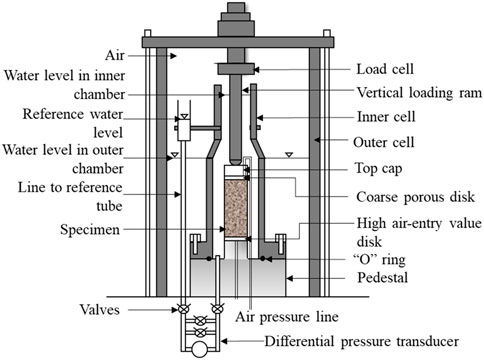
Figure 1. Connected double chamber triaxial (Ng et al., 2002).
Another type is the closed double chamber triaxial apparatus with independent inner and outer chambers that can be pressurized separately (Wheeler, 1988; Sivakumar, 1993; Yin, 2003). Figure 2 shows a double chamber triaxial structure designed by Wheeler (1988). The inner chamber is filled with water, and the volume change is recorded by a pressure-volume controller or a water burette, such as the double chamber structure used by Wheeler (1988). Furthermore, Sivakumar (1993) utilized a DPT to automatically measure the water level change in the inner chamber, with the measurement data recorded automatically by a computer. Yin (2003) added a top cover to the inner chamber and placed the load cell inside the inner chamber, surrounding the inner chamber with the outer chamber. This design addressed issues related to the synchronous extension of the inner chamber’s top under high pressure and water leakage along the loading ram during loading. Carvalho et al. (2018) designed a double chamber triaxial apparatus with a similar structure, where both chambers were pressurized synchronously by a single air pressure controller, and used a high-precision weighing instrument to weigh the mass of the liquid flowing out of the inner chamber to infer the volume change of the specimen.
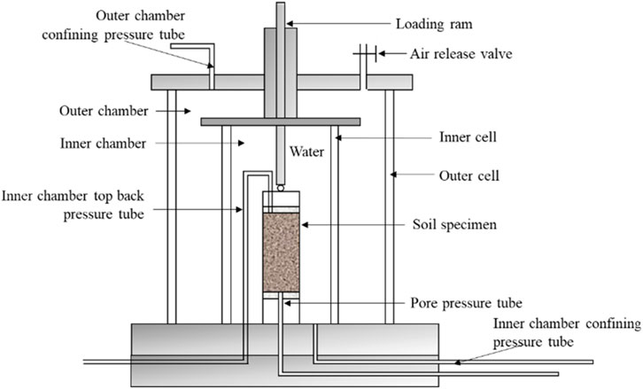
Figure 2. Closed double chamber triaxial (Wheeler, 1988).
However, the above test apparatus still has areas for improvement: (1) The inner chamber could be further minimized while ensuring it does not affect the deformation of the specimen to improve accuracy; (2) The inner chamber’s large size and complex structure make it difficult to completely remove residual air by injecting water after specimen installation. In order to eliminate the influence of bubbles in the chamber, Sivakumar (1993) suggested assembling the inner chamber under air-free water, which requires the inner chamber to have a simple structure, be detachable, small size, without transducers. Based on the existing double chamber volume change measurement principle, this study improves the inner chamber and designs a new inner chamber structure that is simple, compact, high in precision, convenient in test operation, low in cost, and can be applied to different types of triaxial apparatus. Finally, the accuracy of the volume change measurement results of the test apparatus is verified by the saturated soils drained shear test.
2 Improve of double chamber triaxial systems
Figure 3 shows the overall appearance of the double-chamber triaxial test apparatus. Figure 4 is a cross-sectional view of the double chamber structure. Figure 5 shows the disassembly components of the inner chamber structure and the assembly completion diagram. In Figure 5A, “a-j” are respectively the inner wall, nut, water stop cap, top cap, permeable stone, loading ram, specimen base, screw rod, top cover, and inner chamber base; The change of the inner chamber are as follows:
(1) For the standard specimen size of 50 mm diameter and 100 mm height, the inner diameter of the inner chamber is designed to be 60 mm and its inner height is 150 mm, and the maximum allowable radial strain can reach 20%.
(2) The volume of the new inner chamber is further reduced compared to the traditional double chamber structure. Additionally, the load cell is arranged outside the inner chamber, which can effectively reduce the required volume of the inner chamber and improve the precision and accuracy of the volume change measurement system.
(3) The inner chamber is completely separated from the outer chamber, allowing underwater assembly.
(4) The overall height of the inner chamber after installation is 225 mm (see Figure 5B), which can be directly applied to various types of triaxial apparatus without additional processing.
(5) The inner chamber has a simple structure and easy to disassemble (see Figure 5A), and is convenient for pre-vacuuming to remove bubbles after disassembly to reduce the error caused by residual air bubbles during measurement.
(6) The inner chamber is not connected to the outer chamber. The inner and outer pressures are independently controlled by different pressure-volume controllers, ensuring there is no pressure difference between the inside and outside. This reduces the influence of the hysteresis in the pressure change of the outer chamber, and the volume change of the inner chamber can be automatically recorded by the software.
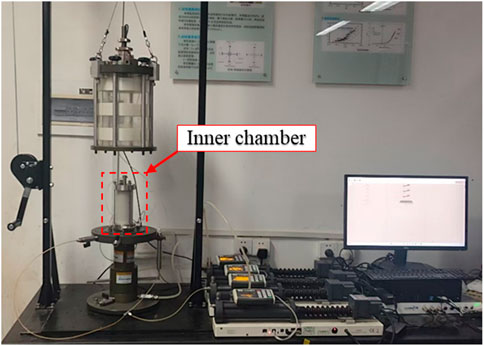
Figure 3. Double chamber triaxial test apparatus.
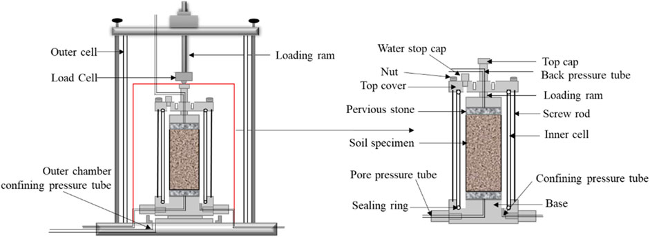
Figure 4. Double chamber triaxial test apparatus structure diagram.
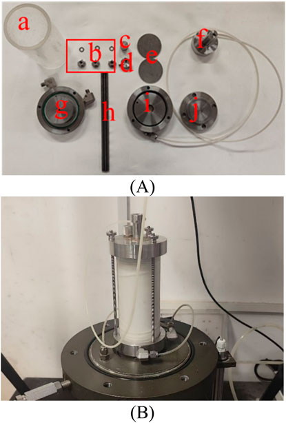
Figure 5. Inner chamber: (A) The inner chamber components disassembly; (B) Inner chamber component assembly.
3 Calibration of the double chamber triaxial system
All experimental instruments have systematic errors during measurement, it must be calibrated in advance. The volume change systematic error is primarily divided into three parts:
(1) Immediate volume change
This refers to the elastic volume change of the system caused by the increase of pressure. Once the pressure increase is completed, the immediate volume change will no longer change. This change is usually related to factors such as the stiffness of the system (including the chamber and pipeline), the compressibility of the chamber liquid, the compressibility of rubber membrane, and the presence of residual air bubbles.
(2) Cyclic volume change
This refers to the periodic fluctuation of volume over time during the testing process. This change is mainly caused by the cyclic change of the measured value due to feedback such as stress servo compensation made by the system. Ng et al. (2002) believe that the fluctuation of the measured value caused by factors such as the temperature difference between day and night also belongs to cyclic volume change.
(3) Creep
This refers to the little volume change that continue to occur over time when the pressure remains unchanged. It is primarily related to the creep characteristics of the material properties, slight leakage of the system.
Volume change calibration tests were carried out using a solid stainless specimen at a constant room temperature of 23°C.
3.1 Volume change calibration
Before the calibration test, the vacuum saturation cylinder is first filled with air-free water. Then, the inner chamber components are placed into the water, and pre-vacuuming is performed, effectively preventing the presence of air in the inner chamber. There are two main reasons for underwater assembly: (1) The phase that the inner chamber components entering into air-free water brings new air into the air-free water. Also, the air in the component pipes, joints, and rubber ring grooves cannot be completely removed. (2) Directly filling the inner chamber with air-free water without underwater assembly leaves air bubbles in the top of chamber.
Figure 6 shows a comparison of the inner chamber components before and after vacuuming. Although the water in the vacuum saturation cylinder is air-free water, there are still many bubbles adhering to the surface of the components after vacuuming. This is because placing the inner chamber components into air-free water introduces air. Before underwater assembly, the components need to be gently shaken underwater and brushed to remove the air bubbles on the surface. Figure 7 shows that the loading ram at the top of the specimen can be divided into two parts. After vacuuming, the loading ram was unscrewed, and air-free water was injected using the controller to ensure there was no residual air in the pipeline. After removing the bubbles, the inner chamber components were assembled underwater.
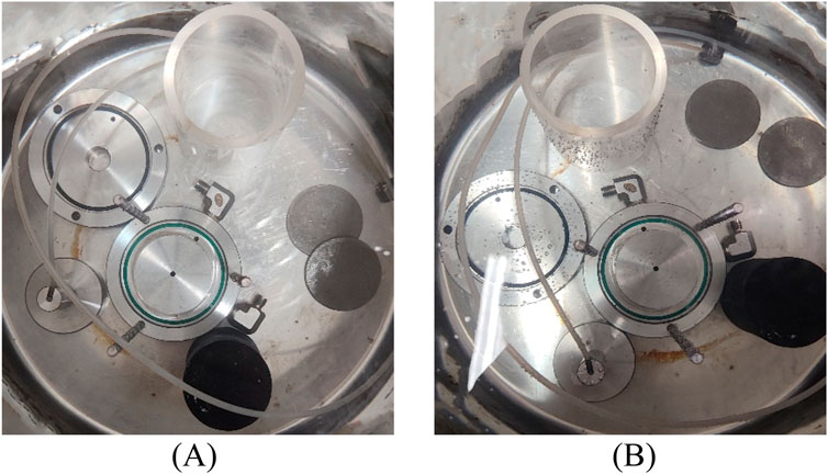
Figure 6. Comparison before and after vacuuming: (A) Before vacuuming; (B) After vacuuming.
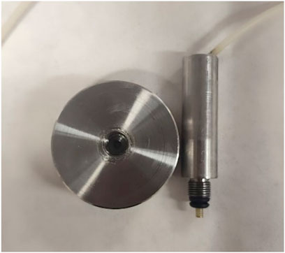
Figure 7. Top loading ram.
After all components were assembled underwater (as shown in Figure 8), the inner chamber was placed in the triaxial outer chamber for airtightness testing. The drainage pipe at the top of specimen was connected to the back pressure controller, and the water stop cap of the inner chamber was closed to completely seal it. Subsequently, the drainage joint “a” at the bottom of the inner chamber was opened, and whether liquid flows out of the joint “a” in Figure 9 was observed. If there is water flowing out of joint “a”, it indicates that the chamber has not been completely sealed (which may be related to whether the bolts are tightened), and it needs to be reassembled underwater.
Figure 8. Assembly of the inner chamber under air-free water.
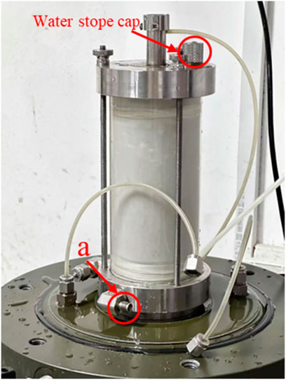
Figure 9. Air tightness test.
The calculation equation for the change in the immediate volume of the inner chamber is as follows:
Where r is the radius of the loading ram, s is the axial displacement, and the specimen compression direction is positive.
The volume of the solid metal specimen changes little with the increase in pressure (Yin, 2003). Therefore, the solid metal specimen is widely used in volume change systematic error calibration tests (Ng et al., 2002; Yin, 2003; Zhang et al., 2014; Chen et al., 2019). Using solid metal specimens can eliminate the influence of soil specimens and calibrate only for the systematic errors of the instrument itself. The dimensions of the stainless specimen are 50 mm × 100 mm. The stainless specimen was installed in the inner chamber following the installation procedure for the soil specimen. During the volume change measurement, the cell pressure of both the inner and outer chambers and the back pressure were first increased to 100 kPa and maintained for a period of time. Then, the cell pressure of both chambers was simultaneously increased by 30 kPa, while the volume of backpressure controller remained unchanged. The B-value was checked and found to be 0.99. After the B value detection was completed, the volume change calibration was performed.
The immediate volume change calibration was based on a back pressure of 100 kPa, with cell pressure increased in steps (the pressure of the inner and outer chambers increases by 50 kPa each time). During the test, the drain valve of the back pressure joint was closed to keep the water volume in the membrane unchanged. At this time, the volume change of the inner chamber caused by the increase in confining pressure is considered the immediate volume change. Calculated by Equation 1, Figure 10A shows the relationship between the volume change of the inner chamber

Figure 10. Volume change: (A) Immediate volume; (B) Creep volume.
The creep calibration was performed after the immediate volume change calibration was completed, with both the inner and outer pressures maintained at 100 kPa for one week. Figure 10B shows the creep result of the inner chamber over this period. The volume changes rapidly during the first 24 h, after which the changes exhibit a linear trend.
Table 1 compares the measurement errors of the double chamber system designed in this study with others existing double-chamber systems. The net confining pressure increases from 0 kPa to 400 kPa. “a” represents specimen diameter 50 mm, height 100 mm; “b” represents specimen diameter 38 mm, height 76 mm; “c” represents specimen diameter 100 mm, height 200 mm.
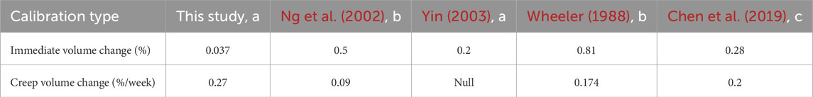
Table 1. Comparison with calibration results of different double-chamber systems.
3.2 Friction calibration
This design minimizes the volume of the inner chamber and improves the measurement accuracy. However, since the load cell is located outside the inner chamber, there is friction between the inner chamber top cover and the vertical loading ram, causing the value measured by the load cell to be the sum of the friction and the actual strength of the specimen. To reduce friction, the contact surface is coated with Teflon and Vaseline, and the friction is calibrated using a high-precision dynamometer. First, the weight of the loading ram was measured by the dynamometer (as shown in Figure 11A), with an average result of 6.18 N from five tests. Then, after assembling the inner chamber, the dynamometer was pulled to raise the loading ram at a uniform speed to measure the sum of the friction force and weight (as shown in Figure 11B), yielding an average of 10.32 N from five tests. The friction force is approximately 4.14 N, resulting in an initial axial stress due to friction of only 2.11 kPa. Using silicone oil or applying lithium-based grease on the contact surface can further reduce friction. (David Suits et al., 2005). During the testing, the initial axial stress is 2∼2.5 kPa without the inner chamber; therefore, initial axial stress of 6.5 kPa was pre-applied at specimen of the double-chamber triaxial test. The direction of friction calibration must be set according to the axial strain direction under other loading stress paths.

Figure 11. Friction calibration: (A) Weight measurement of loading ram; (B) friction measurement.
Tests were conducted using solid rubber specimens (50 mm in diameter and 100 mm in height) both with and without the inner chamber. The test was carried out using two different loading methods: (1) stress loading, where the axial stress is increased to 130 kPa within the same time period and the stress is controlled to be the same; (2) strain loading, the displacement increased to 1.7 mm within the same time period, and the final position was consistent; Friction calibration was performed under different effective confining pressures. The tests were divided into those with and without the inner chamber. In this study, “Friction” indicates the presence of the inner chamber during the calibration test, while “Frictionless” indicates the absence of the inner chamber. Figure 12 shows the test results, indicating that increasing the initial axial stress to 6.5 kPa has little effect on the results.
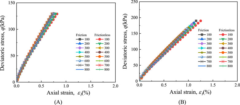
Figure 12. Stress-strain curve with initial axial stress of 6.5 kPa: (A) Stress controlled loading; (B) Strain controlled loading.
3.3 Undisturbed soil shearing test
Due to the metal specimens used during calibration testing, all components of the inner chamber and the specimen can be assembled in air-free water and then placed in the triaxial inner chamber. However, in the soil specimen test, the procedure is slightly adjusted. First, the specimen was installed on the inner chamber base in the atmosphere. After the specimen assembly was completed, the tri-leaflet valve used to protect the specimen was not disassembled (see Figure 13). Instead, as an external constraint, it continued to protect the specimen during the vacuuming. Thus, the specimen has little deformation in both radial and axial directions, avoiding any change in the volume of the specimen when the vacuum was applied. Then the remaining components of the inner chamber and the soil specimen ware placed in a vacuum saturation cylinder for pre-vacuuming. After the vacuum was drawn, the inner chamber was assembled underwater and then placed in the triaxial outer chamber.
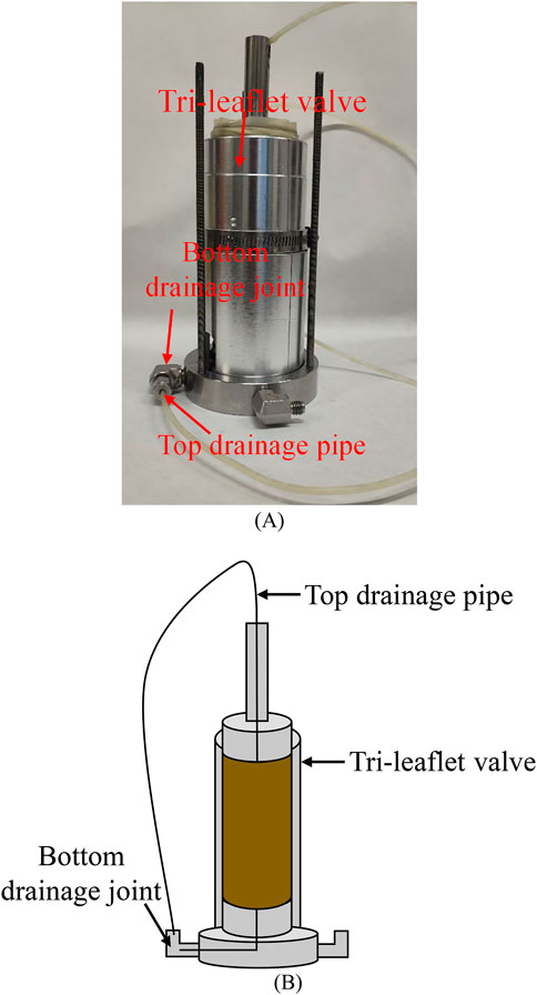
Figure 13. Apply external constraints to the specimen: (A) Physical picture; (B) Diagram.
Generally, in saturated soil drained tests, the volume change of the specimen can be represented by the specimen drained volume. In order to test the measurement precision and accuracy of the apparatus, a drained monotonic shear test was carried out, and the volume change of the inner chamber was compared with the volume of water drained from the specimen. Due to its slower drained shear rate, clay is more susceptible to being influenced by system creep. Therefore, undisturbed soil specimens of soft clay were chosen, sourced from a foundation pit located in Hangzhou, China (see Figure 14). The British GDS stress path triaxial apparatus was used to carry out the consolidation drained shear test. Figure 14 shows the location of the soil utilized in this test and the typical geotechnical profile at that location. The basic physical parameters of the soil specimen are presented in Table 2. Figure 15 shows the particle size distribution curve of soft clay, the diameter of the specimen is 50 mm and the height is 100 mm. To ensure high saturation, in this study the soft clay specimen was saturated under a back pressure of 300 kPa (Wang et al., 2016; Wang et al., 2017; Wu et al., 2017, 2022) and a confining pressure of 310 kPa. The saturation time was not less than 24 h. The B-value was checked and found to be 0.97.
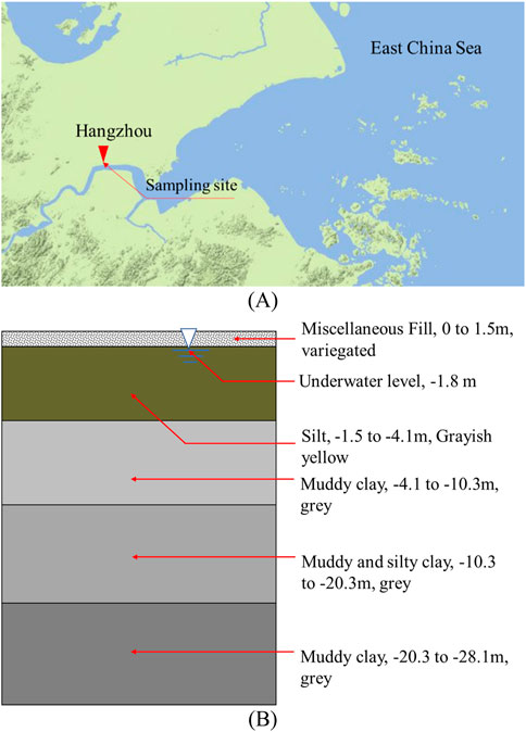
Figure 14. The geographical location of the undisturbed soil: (A) Study area on the map of China; (B) Typical geotechnical profile in the study area.
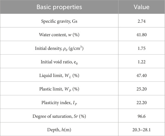
Table 2. Basic properties of the tested soft clay.
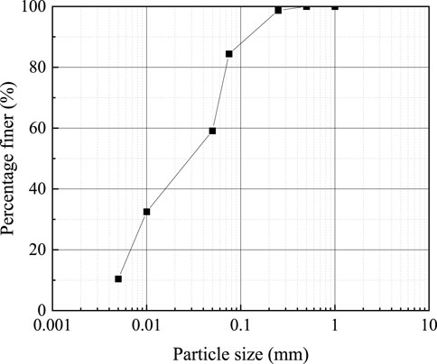
Figure 15. Particle size distribution curve of soil.
Figure 16A shows that during consolidation, the drained volume of the soil specimen was measured to be
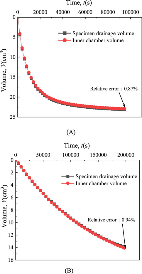
Figure 16. Specimen volume change: (A) Volume change in consolidation; (B) Volume change in shearing.
After consolidation was completed, the “Advanced Loading” test module was used to conduct the drained shear test, with a shear rate of 0.005%/min. Since the confining pressure remains unchanged during shearing, the influence of creep is mainly considered. Figure 16B shows the variation curve of specimen volume with shear time. When shearing is completed, the drained volume of the specimen
4 Conclusion
The current measurement methods of unsaturated soil volume change are summarized, and based on the chamber liquid measurement method, the current double-chamber measuring instrument is introduced and a new type of inner chamber structure is improved. The main conclusions are as follows.
(1) The newly designed and manufactured inner chamber structure overcomes the problem of closed double-chamber triaxial apparatus cannot be assembled underwater, enabling complete underwater assembly. It avoids residual air bubbles in the inner chamber when water is injected, and the inner chamber is easy to disassemble, making it suitable for different models of triaxial apparatus, with strong applicability. It can be used for continuous measurement of unsaturated soil volume changes, and the measurement results are reliable and quite accurate.
(2) When using stainless specimens, the volume change of the inner chamber under net confining pressure of 400 kPa is only 0.037% of the total volume of the specimen, which is a very small error.
(3) Drained shear test was conducted on undisturbed soft clay. The soil specimen drained shear test proved that the designed internal chamber structure is reliable. The measurement errors of the two different methods at the completion of consolidation and shearing were 0.201 cm3 and 0.131 cm3, the measurement errors of 0.102% and 0.067% of the specimen volume, respectively.
Data availability statement
The original contributions presented in the study are included in the article/supplementary material, further inquiries can be directed to the corresponding author.
Author contributions
TW: Methodology, Writing–original draft, Writing–review and editing. CX: Data curation, Formal Analysis, Writing–original draft, Writing–review and editing. HC: Conceptualization, Supervision, Writing–original draft, Writing–review and editing. XX: Data curation, Formal Analysis, Methodology, Writing–original draft, Writing–review and editing. DP: Data curation, Formal Analysis, Writing–original draft, Writing–review and editing. JC: Conceptualization, Data curation, Supervision, Writing–original draft, Writing–review and editing.
Funding
The author(s) declare that financial support was received for the research, authorship, and/or publication of this article. The work presented in this study was financially supported by the National Natural Science Foundation of China Regional Joint Fund (U2006225), the Engineering Research Center of Renewable Energy Infrastructure Construction Technology of the Ministry of Education, and the Zhejiang Provincial Key Laboratory of Engineering Structures and Disaster Prevention and Mitigation Technology for their financial support, which provided a solid material foundation and scientific research platform for this research. Their support is greatly appreciated.
Conflict of interest
Author JC was employed by Zhejiang Geological and Mineral Exploration Institute Co., Ltd.
The remaining authors declare that the research was conducted in the absence of any commercial or financial relationships that could be construed as a potential conflict of interest.
Generative AI statement
The author(s) declare that no Generative AI was used in the creation of this manuscript.
Publisher’s note
All claims expressed in this article are solely those of the authors and do not necessarily represent those of their affiliated organizations, or those of the publisher, the editors and the reviewers. Any product that may be evaluated in this article, or claim that may be made by its manufacturer, is not guaranteed or endorsed by the publisher.
References
Adams, B., Wulfsohn, D., and Fredlund, D. (1996). Air volume change measurement in unsaturated soil testing using a digital pressure-volume controller. Geotechnical Test. J. 19, 12–21. doi:10.1520/GTJ11403J
Bishop, A. W. (1961). “The experimental study of partly saturated soil in the triaxial apparatus,” in Proc International Conference on Soil Mechanics & Foundation Engineering.
Carvalho, T., Campos, T., and Benessiuti Motta, M. (2018). Development of an alternative total volume change measuring system for samples in unsaturated conditions in triaxial tests. doi:10.1061/9780784481684.045
Chen, W.-B., Yin, J.-H., and Feng, W.-Q. (2019). A new double-cell system for measuring volume change of a soil specimen under monotonic or cyclic loading. Acta Geotech. 14, 71–81. doi:10.1007/s11440-018-0629-6
Clayton, C., and Khatrush, S. (1986). A new device for measuring local axial strains on triaxial specimens. Geotechnique 36, 593–597. doi:10.1680/geot.1986.36.4.593
Clayton, C., Khatrush, S., Bica, A., and Siddique, A. (1989). The use of Hall effect semiconductors in geotechnical instrumentation. Geotechnical Test. J. 12, 69–76. doi:10.1520/GTJ10676J
Costa Filho, L. (1985). Measurement of axial strains in triaxial tests on London clay. Geotechnical Test. J. 8, 3–13. doi:10.1520/GTJ10851J
David Suits, L., Sheahan, T., Alshibli, K., and Williams, H. (2005). A true triaxial apparatus for soil testing with mixed boundary conditions. Geotech. Test. J. 28, 12679. doi:10.1520/GTJ12679
Desrues, J., Chambon, R., Mokni, M., and Mazerolle, F. (1996). Void ratio evolution inside shear bands in triaxial sand specimens studied by computed tomography. Géotechnique 46, 529–546. doi:10.1680/geot.1996.46.3.529
Gachet, P., Geiser, F., Laloui, L., and Vulliet, L. (2007). Automated digital image processing for volume change measurement in triaxial cells. Geotechnical Test. J. 30, 98–103. doi:10.1520/GTJ100309
Geiser, F. (1999). Comportement mécanique d’un limon non saturé. Available at: https://api.semanticscholar.org/CorpusID:107729313.
Goto, S., Tatsuoka, F., Shibuya, S., Kim, Y., and Sato, T. (1991). A simple gauge for local small strain measurements in the laboratory. SOILS Found. 31, 169–180. doi:10.3208/sandf1972.31.169
Klotz, E., and Coop, M. (2002). On the identification of critical state lines for sands. Geotechnical Test. J. 25, 289–302. doi:10.1520/GTJ11090J
Laloui, L., Péron, H., Geiser, F., Rifa’i, A., and Vulliet, L. (2006). Advances in volume measurement in unsaturated soil triaxial tests. Soils Found. 46, 341–349. doi:10.3208/sandf.46.341
Laudahn, A., Sosna, K., and Boháč, J. (2005). A simple method for air volume change measurement in triaxial tests. Geotechnical Test. J. 28, 313–318. doi:10.1520/GTJ12656
Maatouk, A. (1993). Application des concepts d’état limite et d’état critique à un sol partiellement saturé effondrable. Available at: https://api.semanticscholar.org/CorpusID:127610503.
Ng, C. W. W., Zhan, L. T., and Cui, Y. J. (2002). A new simple system for measuring volume changes in unsaturated soils. Can. Geotech. J. 39, 757–764. doi:10.1139/t02-015
Romero, E., Facio, J. A., and Lloret, A. (1997). A new suction and temperature controlled triaxial apparatus.
Sachan, A., and Penumadu, D. (2007). Strain localization in solid cylindrical clay specimens using digital image Analysis (DIA) technique. Soils Found. 47, 67–78. doi:10.3208/sandf.47.67
Sun, D. A., Sheng, D. C., Cui, H. B., and Li, J. (2012). “Effect of density on the soil-water-retention behaviour of compacted soil,” in Unsaturated soils 2006, 1338–1347. doi:10.1061/40802(189)110
Wang, Y., Gao, Y., Guo, L., Cai, Y., Li, B., Qiu, Y., et al. (2017). Cyclic response of natural soft marine clay under principal stress rotation as induced by wave loads. Ocean. Eng. 129, 191–202. doi:10.1016/j.oceaneng.2016.11.031
Wang, Y.-K., Guo, L., Gao, Y.-F., Qiu, Y., Hu, X.-Q., and Zhang, Y. (2016). Anisotropic drained deformation behavior and shear strength of natural soft marine clay. Mar. Georesources & Geotechnol. 34, 493–502. doi:10.1080/1064119X.2015.1081653
Wheeler, S. J. (1988). The undrained shear strength of soils containing large gas bubbles. Géotechnique 38, 399–413. doi:10.1680/geot.1988.38.3.399
Wu, T., Cai, Y., Guo, L., Ling, D., and Wang, J. (2017). Influence of shear stress level on cyclic deformation behaviour of intact Wenzhou soft clay under traffic loading. Eng. Geol. 228, 61–70. doi:10.1016/j.enggeo.2017.06.013
Wu, T., Tong, J., Sun, H., Yuan, Z., and Guo, L. (2022). Common characteristics between cyclic behaviours at different frequencies and monotonic behaviours of clay. Can. Geotech. J. 59, 1553–1567. doi:10.1139/cgj-2021-0259
Xia, Y., Mu, C., Li, W., Ye, K., and Wu, H. (2022). Study of dynamic evolution of the shear band in triaxial soil samples using photogrammetry technology. Sustainability 14, 14660. doi:10.3390/su142114660
Yin, J.-H. (2003). A double cell triaxial system for continuous measurement of volume changes of an unsaturated or saturated soil specimen in triaxial testing. Geotechnical Test. J. 26, 353–358. doi:10.1520/GTJ11307J
Zhang, X., Li, L., Chen, G., and Lytton, R. (2015). A photogrammetry-based method to measure total and local volume changes of unsaturated soils during triaxial testing. Acta Geotech. 10, 55–82. doi:10.1007/s11440-014-0346-8
Keywords: unsaturated soil, volume change, triaxial test, calibration, underwater assembly
Citation: Wu T, Xia C, Chen H, Xu X, Pan D and Chen J (2025) An improved double chamber triaxial volume change measurement system for unsaturated soils. Front. Built Environ. 10:1518953. doi: 10.3389/fbuil.2024.1518953
Received: 29 October 2024; Accepted: 09 December 2024;
Published: 06 January 2025.
Edited by:
Sudhakar Rao, Retired, Bangalore, IndiaReviewed by:
Ramakrishna Bag, Indian Institute of Technology Patna, IndiaTácio De Campos, Pontifical Catholic University of Rio de Janeiro, Brazil
Copyright © 2025 Wu, Xia, Chen, Xu, Pan and Chen. This is an open-access article distributed under the terms of the Creative Commons Attribution License (CC BY). The use, distribution or reproduction in other forums is permitted, provided the original author(s) and the copyright owner(s) are credited and that the original publication in this journal is cited, in accordance with accepted academic practice. No use, distribution or reproduction is permitted which does not comply with these terms.
*Correspondence: Chaobo Xia, eGlhY2hhby1iby56anV0QGhvdG1haWwuY29t