 Mohammed Mayhoub
 Haitham Selim
 Abdullah Abuzaid
- 1Architecture Department, Faculty of Engineering, Al-Azhar University, Cairo, Egypt
- 2Department of Architecture, College of Engineering and information Technology, Onaizah Colleges, Qassim, Saudi Arabia
- 3Architectural Engineering Department, College of Engineering, Imam Mohammad Ibn Saud Islamic University (IMSIU), Riyadh, Saudi Arabia
This study explores the geometrical design of windcatchers, a traditional architectural element offering a sustainable solution for natural ventilation in hot, arid climates. The growing demand for energy-efficient cooling has renewed interest in windcatchers, but their integration into contemporary architecture remains limited due to knowledge gaps and practical challenges. The study aims to: (1) offer architects practical guidelines for incorporating windcatchers into their designs, (2) create a research roadmap to address underexplored geometrical design parameters, and (3) standardize design parameters for each windcatcher component. The review identified well-studied components, such as aerodynamic advantages of curved top surfaces. It highlighted inconsistencies in literature and unvalidated findings, such as conflicting findings on the optimal outlet-to-inlet area ratio. It also revealed unexplored design parameters that require further investigation. The study developed a structured research roadmap with standardized design parameters, facilitating the creation of a comprehensive design guide for architects that ultimately enabling the more widespread and effective use of windcatchers in contemporary architectural practice.
1 Introduction
Natural ventilation plays a crucial role in passively supplying fresh air to buildings, particularly in hot, arid regions where it can meet cooling demands without relying on energy-intensive mechanical air conditioning systems. As energy costs and environmental impacts become more pressing concerns, the appeal of natural ventilation has grown, offering a sustainable alternative that not only achieves thermal comfort but also ensures acceptable indoor environmental quality (Hughes et al., 2012).
The windcatcher is a traditional architectural element originating from the Middle East, designed to facilitate natural ventilation in environments where conventional vertical windows are ineffective (Figure 1) (Boloorchi and Eghtesadi, 2014). Structurally, a windcatcher is a tall, capped tower that rises above its surroundings, featuring one or more open tops oriented toward the prevailing wind direction. It includes an air well that channels the captured air into the interior spaces of a building (Fathy and Abd-Elrahman, 1985; Chohan and Awad, 2022). Windcatcher does not necessarily cool the air itself, but rather relies on the rate of airflow to provide a cooling effect (Fathy, 1986; Suleiman and Himmo, 2012; Varela-Boydo et al., 2021; Jomehzadeh et al., 2020). The windcatcher can operate in two distinct modes: channelling airflow downward through direct wind entry or guiding airflow upward using a temperature gradient. A combined system, using either two separate devices or a single device with both inlet and exhaust functions, can provide a comprehensive natural air delivery and extraction solution (Saadatian et al., 2012). Windcatchers are sometimes integrated with modern technologies for cooling, heating, or dehumidification to overcome challenges such as reduced efficiency on calm days and to extend their applicability in extreme cold and hot environments (Liu et al., 2024; Kahkzand et al., 2024; Heidari et al., 2024).
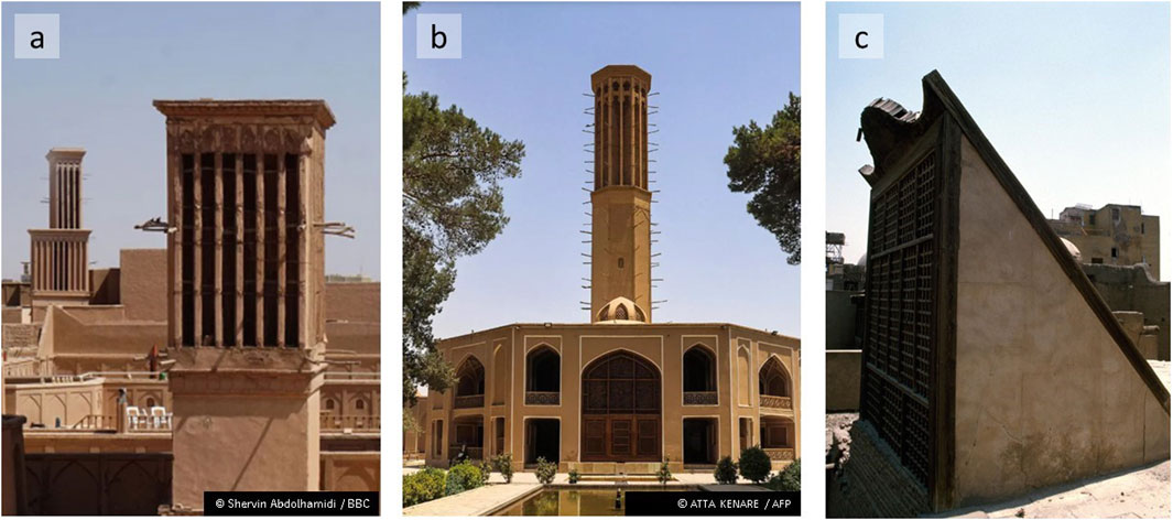
Figure 1. Traditional windcatchers from: (A, B). Yazd, Iran, and (C). Cairo, Egypt.
Numerous efforts have been made to enhance Windcatchers performance and adapt them for use in contemporary architecture. These improvements focus on refining the windcatcher components themselves and integrating additional elements to either increase airflow volume and speed or cool the incoming fresh air. For example, the incorporation of “wing walls” has been suggested to guide airflow into the windcatcher inlet opening (Nejat et al., 2016a). The Anti-Short-Circuiting Device (ASCD) proposed to address the air short-circuiting issue that arises in windcatchers with both inlet and exhaust openings (Nejat et al., 2016b). The addition of louvers has also been shown to increase airflow rate (Liu et al., 2011; Hughes and Ghani, 2010). Some windcatchers incorporate dampers and egg crate grilles to facilitate the movement of large volumes of air (Elmualim, 2006). Various cooling techniques have been developed to enhance the performance of windcatchers. These include designs with wetted curtains hung within the air shaft or wetted evaporative cooling pads mounted at the entrance (Bahadori et al., 2008). Additionally, methods like shower towers (El-Shorbagy, 2011), moistened pad (Soltani et al., 2018) and helical coil heat transfer device (Pelletier and Calautit, 2022) have been implemented to enhance cooling performance in hot climates. Conversely, in cold climates, heating techniques like heat pipes have been employed (Calautit et al., 2016). Other studies have focused on optimizing windcatcher component geometry, positions or orientation (Sadeghi et al., 2017; Chand et al., 1990; Ghadiri et al., 2013; Dehghani-sanij et al., 2015; Attia, 2009).
One notable development in this field is the production of the commercial windcatcher systems. These systems are compact, lightweight, and have lower elevation above roofs. They typically consist of four (or circular) external louver banks designed to catch the breeze from any direction. Fresh air is drawn in from the windward side and directed into the building, while stale air is extracted from the leeward side (Liu et al., 2024; Khan et al., 2008; Monodraught Ltd, 2017; Calautit et al., 2014).
Despite the enduring appeal of windcatchers in contemporary architecture, purely traditional solutions are often difficult to implement and may not be well-received by modern architects (Attia and De Herde, 2009). Emerging commercial trends in windcatcher technologies reflect a blend of traditional principles with modern advancements. The integration of windcatcher into contemporary architecture has been limited by insufficient knowledge, practical experience, the challenge of adapting them to meet modern needs, and the lack of detailed market data (Liu et al., 2024).
Although considerable research has been conducted to examine how design parameters influence windcatcher performance, a review of the literature reveals that certain parameters receive more attention than others, leaving several design aspects insufficiently addressed. This study aims to address these gaps by exploring the current understanding of the geometrical design of contemporary windcatchers, with three main objectives:
I. To assist architects and building designers in effectively incorporating windcatchers into their designs by utilizing the available data.
II. To develop a detailed research roadmap that identifies and prioritizes key windcatcher components requiring in-depth investigation. This focused research will pave the way for the future creation of a comprehensive design guide, optimizing windcatcher geometry for enhanced performance and efficiency.
III. To standardize design parameters for each component, ensuring consistency during investigations.
This study excludes aspects already covered in previous reviews on windcatcher research, such as cooling and heating techniques, integration with other passive or mechanical ventilation systems, and the impact of the surrounding natural or urban context (Hughes et al., 2012; Jomehzadeh et al., 2020; Liu et al., 2024). The influence of windcatcher geometry, which is the focus of the current study, has been partially addressed in reviews by Hughes et al. (2012), Jomehzadeh et al. (2020), and briefly mentioned in Sangdeh and Nasrollahi (2022). However, this review stands out as more comprehensive than the most recent review on geometrical aspects published in 2020. It is more focused, explores new dimensions, and presents a detailed roadmap highlighting under-researched areas and suggests standard design parameters for each component.
2 Methods
This review undertook a comprehensive literature search on the geometrical design of windcatchers. The literature search was conducted using the scientific databases ScienceDirect, Scopus, and Web of Science without restrictions on publication date. The following selection criteria ensured the relevance and quality of the reviewed articles:
• Articles selected were published in English.
•Articles selected included peer-reviewed journal articles, review papers, and conference proceedings to ensure scientific rigor.
•Each article had to contain one or more of the key terms ‘windcatcher(s)”, “Wind catcher(s)” , “Wind-catcher(s)”, or “Wind tower” within the title, abstract, or keywords, as these terms are commonly used to describe the intended passive natural ventilation system.
•Only articles available online were included to enable full-text analysis.
The initial search yielded 913 articles, filtered through a three-phase process to ensure topical relevance and quality:
•Phase 1: Topical Relevance–Unrelated articles were excluded. For example, papers focused on “wind turbine towers” frequently appeared due to the common use of the term “Wind tower” in other research areas. This phase narrowed the pool to 489 articles.
•Phase 2: Duplicate Removal–Articles indexed in multiple databases were identified and duplicates removed, reducing the total to 228 unique papers.
•Phase 3: Content Analysis–The remaining articles underwent an in-depth content analysis. Abstracts, study parameters, and conclusions were examined to identify studies with a specific focus on the geometrical aspects of windcatcher design. This phase resulted in a short list of 56 high-relevance articles.
The final selection of articles underwent a structured two-step analysis to systematically categorize and evaluate windcatcher components:
•Component Identification and Categorization–All windcatcher components referenced in the selected articles were extracted and classified.
•Research Status Evaluation–Each component, whether primary or supplementary, was assessed to determine the extent of existing research. Components were classified into three categories based on their research status: (a) Well-studied components with established design guidelines readily available for practitioners, (b) Partially studied components where some research exists but further investigation/validation is needed to fully support design decisions, and (c) lacking sufficient research components representing significant knowledge gaps, highlighting areas where additional research is crucial to advance understanding and innovation in windcatcher design. This categorization aimed to provide a roadmap for future research and to assist practitioners in identifying validated design parameters.
3 Results
Windcatcher components, as derived from the literature, are categorized into two groups. Primary components are those essential to the fundamental geometry and structure of any windcatcher forming. Supplementary components are optional features that can be incorporated to improve windcatcher performance (Figure 2). The features and design parameters of each component are addressed in the following sections.
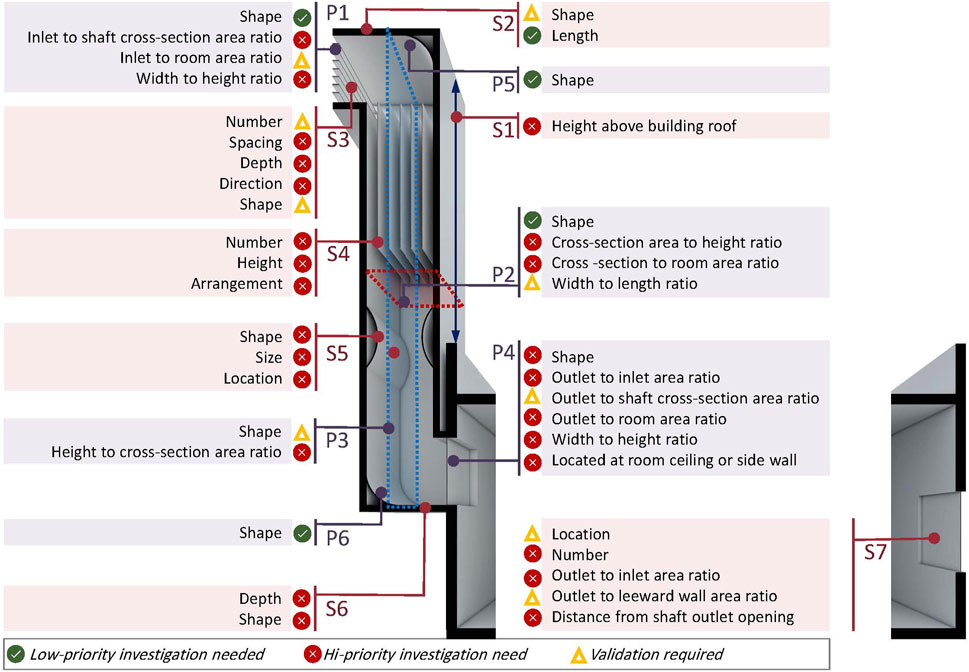
Figure 2. Windcatcher primary and supplementary components.
3.1 Windcatcher primary components
3.1.1 Inlet openings
The performance of windcatchers is significantly influenced by the number and configuration of the inlet openings, which are typically designed based on the local climate. One-sided windcatcher features a single, large opening that faces the predominant wind direction. Traditionally, it requires an additional opening(s) (room outlet window) on the opposite side to let the air to exhaust out of the building (Jomehzadeh et al., 2020; Attia and De Herde, 2009). Two-sided windcatcher incorporates two openings on opposite sides of the windcatcher, allowing fresh air to enter through one side, while the other acts as a chimney and suck indoor air (Sangdeh and Nasrollahi, 2022). Four-sided windcatcher features openings on all four sides, capturing wind from any direction.
A multi-directional dual-channel rotary scoop windcatcher was proposed for use in contemporary windcatcher to ensure that the windcatcher opening is consistently facing the airflow directions (Li et al., 2024; Li et al., 2023a). To optimize the capture of fresh air from all directions, some contemporary windcatchers also proposed the incorporation of flap-fin louvers to allow wind to flow only one way into the windcatcher’s supply channel (Li et al., 2023b).
The one-sided windcatcher is ideal for regions with consistent, predictable wind patterns, as the entire cross-sectional area functions as an inlet for airflow. Meanwhile, in two- or multi-sided windcatchers, only half or less of the cross-section delivers air to indoor space (Sangdeh and Nasrollahi, 2022). Two-sided designs enhance cross-ventilation, particularly in areas with fluctuating wind directions. Four-sided windcatchers offer maximum flexibility and consistent performance across varied conditions, though they are more costly and complex to construct. Therefore, the choice of windcatcher design should account for local climate, prevailing wind patterns, and the specific ventilation needs of the building.
The inlet opening design parameters include also its size and shape. The area of the inlet opening is typically equivalent to the cross-sectional area of the shaft, which is around 3% of the floor area of the ventilated space (Attia and De Herde, 2009). However, in traditional windcatchers found in Sanliurfa, Turkey, the inlet size is narrower than the shaft cross-section (Bekleyen and Meli̇koğlu, 2021).
For two-sided windcatchers, the impacts of different inlet shapes—square, rectangular, and circular (of the same area)—on ventilation performance have been studied. It was found that the geometry of the inlet significantly affects airflow patterns, rates, and velocity. Moreover, increasing the length-to-width ratio of rectangular openings improves the ventilation flow rate (Niktash and Huynh, 2014).
3.1.2 Shaft cross-section
It is well established that increasing the cross-sectional area of a windcatcher shaft leads to greater airflow, as larger openings allow more air to pass through (Sangdeh and Nasrollahi, 2022). Consequently, the design parameters of the shaft’s cross-section have garnered significant attention in research.
In a study of various four-sided windcatcher configurations in Yazd, Iran, it was observed that reducing the shaft width from 2.5 m to 2 m, creating a more longitudinal shape, increased airflow velocity by up to 34%. Further reducing the width from 2 m to 1.5 m resulted in up to 50% increase in velocity. However, the smaller width (1.5 m) directed airflow at high velocities towards the lower areas of the room, leading to uneven temperatures and causing discomfort (Hosseini et al., 2016). Based on literature survey, Benkari et al. concluded that the best ratio of the windcatcher length and width to that of the room it serves, is approximately 1:4 (Benkari et al., 2017). Though, further investigation is required to validate this finding.
Regular polygons are the most common shapes for traditional windcatcher cross-sections. While the rectangular form is most prevalent, other shapes such as circular, hexagonal, and octagonal are also used Jomehzadeh et al. (2020). A comparison between square, hexagonal, and circular six-sided windcatchers revealed that, on average, the hexagonal cross-section delivered 19% more airflow than the square design under various wind speeds and angles (Farouk, 2020). However, at a 0° wind angle, the square windcatcher proved more effective (Sangdeh and Nasrollahi, 2022). When evaluating the performance of four-sided windcatchers with rectangular and circular cross-sections under different wind directions, the square cross-section consistently performed better (Elmualim and Awbi, 2002; Maneshi et al., 2012). Similarly, contemporary windcatchers using different cross-sections demonstrated that circular designs produced the lowest air change rates and indoor air velocities (Farouk, 2020).
A longitudinal windcatcher, featuring a rectangular cross-section with elongated inlet and outlet openings, was developed for ventilating a building basement. This design resulted in evenly distributed indoor air movement at the occupant level, demonstrating the advantages of a longitudinal configuration (Satwiko and Tuhari, 2017). The impact of shaft cross-section area and geometry on a wind exchanger, which can function as a windcatcher, has been experimentally evaluated. The study showed that a larger cross-section generally improves performance, and a rectangular cross-section outperformed a square one, especially when the longer axis was aligned perpendicular to the wind flow (Cruz-Salas et al., 2018).
Balabel et al. proposed a one-sided windcatcher with a partial-cylinder shaft and a partial circular cross-section ranging from 60° to 90°. Their findings indicated that this design produced a higher pressure coefficient compared to traditional rectangular windcatchers (Balabel et al., 2021).
3.1.3 Shaft longitudinal section
The key design parameters of the windcatcher shaft’s longitudinal section include its height and shape. Traditional windcatcher shafts are typically one-story, sometimes two-story structures, with multi-story designs being rare (Sangdeh and Nasrollahi, 2022; Shayegani et al., 2024). Recent research recommends limiting the height of windcatchers to no more than three stories (Mohamed and El-Amin, 2022), aligning with findings by Hosseini et al., which showed that increasing the windcatcher height from 8 m to 10 m reduced airflow circulation in the served spaces (Hosseini et al., 2016). Sensitivity analyses have further confirmed that increasing shaft height results in a decrease in mass flow rate (Sheikhshahrokhdehkordi et al., 2020), a conclusion also supported by the work of Ghadiri et al. (2014).
The longitudinal section of most windcatcher shafts is typically straight. However, an investigation into the influence of shaft shape on airflow speed found that a curved shaft shape delivers superior performance in terms of airflow velocity (Alwetaishi and Gadi, 2021).
3.1.4 Shaft outlet opening
The shaft outlet opening can be vertical, such as a window located on the shared side wall between the room and the shaft, or horizontal, positioned on the ceiling of the room. The size and shape of windcatcher shaft outlet openings are not often addressed in the literature, likely because they are typically rectangular, with an area equal to the shaft’s cross-section. However, a novel design of a one-sided windcatcher with a shaft cross-section of 100 cm × 100 cm proposed a rectangular outlet opening measuring 100 cm × 62.5 cm. The reduced height was achieved by inclining the bottom surface of the shaft, resulting in more uniform airflow (Foroozesh et al., 2022). While promising, these findings require further validation.
The geometry of the outlet opening in two-sided windcatchers also impacts ventilation performance. Research shows that the shape of the outlet significantly influences airflow patterns, rate, and velocity, with a clear relationship between the length-to-width ratio of rectangular outlets and the quality of ventilation (Niktash and Huynh, 2014).
Regarding the outlet location, in a one-sided windcatcher, transforming the outlet opening from a side window to a ceiling opening reduces the mean velocity and airflow rate while increasing the mean age of air (Heidari and Eskandari, 2022).
3.1.5 Shaft top surface
Traditionally, the top surface of windcatcher shafts is inclined at angles ranging from 30° to 45°, although some designs feature a flat, horizontal surface (Nessim et al., 2023). More recently, curved top surfaces—designed as quarter-circles with radius equal to the shaft width—have been explored (Sheikhshahrokhdehkordi et al., 2020). At a 0° wind angle, windcatchers with a curved top surface demonstrated a 10% and 4.5% increase in efficiency compared to flat and inclined tops, respectively. However, the inclined top design proved less sensitive to changes in wind angles relative to the opening (Dehghan et al., 2013). Further comparisons between flat and curved top surfaces revealed that the curved design produced a higher mass flow rate by smoothing airflow into the duct, thereby reducing energy loss (Sheikhshahrokhdehkordi et al., 2020), which agree with the findings obtained by Esfeh et al. (2012). Additionally, Benkari et al. noted that curved-top windcatchers provided more uniform airflow distribution compared to those with inclined tops (Benkari et al., 2017). Investigation of one-sided windcatchers with varying top surface tilt angles indicated that a 30° tilt angle yielded slight performance improvement (Alsailani et al., 2021).
3.1.6 Shaft bottom surface
The shape of the windcatcher shaft’s bottom surface is rarely discussed in the literature and is typically a flat, horizontal plane. However, a novel design of a one-sided windcatcher incorporated an inclined bottom surface, which was found to result in more uniform airflow distribution throughout the space (Foroozesh et al., 2022). Similarly, the bottom surface of a two-sided windcatcher has been chamfered at different angles. It was found that an angle of 55° increased air exchange effectiveness by about 14% (Carreto-Hernandez et al., 2022). Additionally, experiments with a curved bottom surface demonstrated an increase in the speed of the inflow stream. However, this design also caused the airflow to be directed towards the lower levels of the room, creating large rotating flows in the upper areas, which may lead to uneven air distribution and potential discomfort (Hosseini et al., 2016).
3.2 Windcatcher supplementary components
3.2.1 Windcatcher projection
The optimal projection height of a windcatcher above a building’s roof depends on various factors, including the climate, surrounding structures, windcatcher type, and cross-section design (Sangdeh and Nasrollahi, 2022). The ideal height typically ranges between 6 and 9 m. For instance, in the climates of Amman (Jordan) and Erbil (Iraq), a tower height of 9 m has been found to provide the best airflow performance (Badran, 2003; Ismail and Miran, 2019). Meanwhile, in Yazd (Iran), the traditional windcatchers perform optimally at a height of 6 m (Ghadiri et al., 2011). A 6 m height is often preferred for both economic and aesthetic reasons (Ismail and Miran, 2019).
Traditional Egyptian windcatchers (Malqaf) usually do not extend above the roofline. These structures, with their single-story height and only the opening visible from above, are designed to capture lower-altitude winds, which are more favourable in the region. Additionally, the narrow spacing between the blades in the windcatcher helps to block undesirable dusty desert winds from entering the building. The windcatcher’s roof is typically sloped between 30° and 45°, aligning with prevailing winds that blow consistently from one direction (Boloorchi and Eghtesadi, 2014; Attia and De Herde, 2009).
In areas where surrounding buildings are lower than the windcatcher, ventilation rates can be enhanced. However, taller adjacent buildings can cause two-sided windcatchers to function like chimneys, drawing indoor air outside (Afshin et al., 2014).
3.2.2 Inlet opening extension
Inlet extensions, or walls, can be employed to guide airflow towards the windcatcher’s inlet opening and separate high-pressure zones from low-pressure areas above the structure. The upper, lower, or side surfaces of the inlet opening can be extended in various ways, with different configurations yielding varied results. In two-sided windcatcher configurations, most inlet extension designs have been shown to enhance air induction into the building (Varela-Boydo and Moya, 2020). The impact of straight inlet extension length has been analysed by examining various ratios of the extension length to the shaft depth in one-sided windcatchers. Significant performance improvements were observed up to a ratio of 0.5, with only a modest 1.8% increase in airflow when the ratio was extended from 0.5 to 1. Further increases in the extension ratio could lead to a reduction in airflow rate (Alsailani et al., 2021).
Three inlet extension configurations—straight, divergent, and bulging convergent—were tested using a two-sided windcatcher. The results indicated that the divergent inlet design performed best, capturing 2.55% more airflow than the straight inlet and 4.70% more than the bulging convergent inlet at high wind speeds (6 m/s). At lower wind speeds (1 m/s), the performance difference was smaller, with only a 1.4% increase in airflow compared to the straight inlet (Abdo et al., 2020).
The performance of circular nozzle-shaped extensions with varying radii in one-sided windcatchers has been tested. Results indicate that the incorporation of this feature cannot effectively lead to a higher airflow rate (Alsailani et al., 2021).
Wing walls, incorporated into the inlet opening design, have been studied for their performance under low wind conditions. Experiments with varying side wing wall angles (ranging from 5° to 70°) on two-sided windcatchers indicate that the optimal angle for enhancing inflow lies between 15° and 30° (Nejat et al., 2016a). In addition to the two side wings, incorporating an upper extension of varying lengths has been shown to enhance the performance of windcatchers, though longer extensions result in only slight improvements in ventilation rates (Nejat et al., 2021). Additional study has explored the effect of upper extension angles (ranging from 0° to 90°) on ventilation performance of two-sided windcatcher, with a 30° angle emerging as optimal (Nejat et al., 2024).
3.2.3 Inlet opening fins
Efforts have been made to integrate fins or louvers into the inlet opening to improve windcatcher performance. The use of finned, curved inlet openings has been shown to significantly enhance the induced air mass flow rate. These fins act as flow straighteners, making the airflow more uniform and reducing radial velocities (Sheikhshahrokhdehkordi et al., 2020).
An evaluation of the performance of a four-sided windcatcher with varying numbers of louvers and louver lengths has been conducted. The findings indicate that the windcatcher achieves optimal performance when the projection length of the louvers equals the gap between two adjacent louvers. Increasing the number of louvers enhances performance up to a certain point; however, a short-circuiting effect occurs when the number of louver layers exceeds six (Liu et al., 2011).
The incorporation of curved guide vanes, with varying numbers and radii, at the bend of the inlet opening in a one-sided windcatcher has been tested. The results show that introducing these guide vanes significantly affects the airflow characteristics. The vanes smoothen the flow through the inlet bend, resulting in improved flow uniformity at the windcatcher outlet, thereby enhancing overall performance. Increasing both the number and radius of the vanes enhanced the airflow rate, with improvements of up to 29% observed (Alsailani et al., 2021).
3.2.4 Shaft partitions
Dividing the cross-section of the windcatcher shaft into smaller partitions can influence airflow velocity and turbulence (Sangdeh and Nasrollahi, 2022). A study analysing different internal partition arrangements in traditional four-sided Iranian windcatchers found that redesigning the partitions and increasing their number enhanced both room air velocity and airflow uniformity inside the building (Hosseinnia et al., 2013).
3.2.5 Shaft nozzle
Integrating a nozzle within the windcatcher shaft has been explored as a means to improve performance. Research on various two-sided windcatcher configurations revealed that the most effective design for maximizing mass flow rate and increasing air velocity at the nozzle throat featured a curved shape with finned inlet openings, the longest divider reaching the top of the nozzle, and a convergent-divergent nozzle type (Sheikhshahrokhdehkordi et al., 2020).
3.2.6 Shaft outlet opening extension
In some designs, an extension connects the shaft outlet with the serviced space (Varela-Boydo et al., 2021; Foroozesh et al., 2022). However, the impact of design parameters for this feature on windcatcher performance has not been thoroughly investigated.
3.2.7 Room outlet window
Combining a windcatcher with a room outlet window(s) creates cross-ventilation, which plays a crucial role in accelerating airflow (Attia and De Herde, 2009; Wu et al., 2021; Cruz-Salas et al., 2014). An evaluation of opposing one-sided windcatchers and room outlet windows with varying ratios found that the highest Air Changes per Hour (ACH) was achieved with a 0.6 ratio between the room outlet window and the outlet window wall (Attia and De Herde, 2009).
Evaluation of airflow and thermal comfort in a room ventilated with a two-sided wind catcher, featuring different room outlet window sizes and elevations, revealed that lowering the outlet elevation increases flow rate. The study also found that a 30% area-to-wall ratio between the outlet size and the room’s leeward wall provides optimal ventilation and thermal comfort (Goudarzi et al., 2021).
Further analysis of different room outlet window sizes and types on cross-ventilation performance showed that placing the outlet window very close to the windcatcher does not increase airflow. However, enlarging the room outlet window while keeping the inlet opening area constant results in a continuous increase in induced airflow into the building. When using a window in combination with a one-sided windcatcher, increasing the window area beyond an outlet-to-inlet ratio of 1.0 provides no additional airflow benefit. The highest airflow rate occurs when the window is centred on the leeward façade (Montazeri and Montazeri, 2018).
To maintain consistent airflow based on the Bernoulli effect, the same volume of air that enters the space must exit. Reducing the inlet opening area while keeping the room outlet window fully open accelerates airflow. A parametric analysis of various windcatcher designs, considering dimensions, proportions, and opening ratios, found that increasing the outlet window area to 200% relative to the inlet opening enhances airflow and promotes temperature reduction (Mohamed and El-Amin, 2022). Similarly, Tantasavasdi et al. concluded that an inlet-to-outlet opening ratio of 1:2 provides best indoor air velocity (Tantasavasdi et al., 2024).
4 Discussion
The data collected on both the primary and supplementary components of windcatchers provides essential insights that align with the study’s three main objectives: assisting architects in effectively incorporating windcatchers into building designs, guiding researchers in identifying critical design parameters that require further investigation, and establishing standardized parameters for design and research consistency. The following three sections address each of these objectives separately.
4.1 Incorporating windcatchers into building design
Many components of windcatchers have been thoroughly investigated. However, critical data gaps remain, which are essential for architects to effectively integrate windcatchers into building designs. While inherited knowledge and extensive research have provided valuable insights and recommendations for various design parameters, many of these are specific to particular climatic conditions and urban contexts. This study aims to gather, categorize, and present the available data to serve as a foundation for incorporating windcatchers during the early stages of building design. Since CFD simulation tools are not commonly mastered by architects, this study provides practical guidance for early design considerations. This section outlines key values, recommendations, and considerations for each component. Table 1 summarizes the recommended geometrical design parameters. However, these recommendations are not always consistent, likely due to variations in the architectural aspects of the case studies, the climatic and urban context, and the different computational parameters and settings used in the studies (Alsailani et al., 2021). Therefore, these recommendations should be applied cautiously, serving as general design guidelines rather than definitive solutions, as they are influenced by varying architectural, climatic, and computational factors. This study acknowledges its limitations and emphasizes the need for context-specific adaptation, further research to address data gaps, validation of existing findings, resolution of conflicting results, and refinement of practical applications for more robust integration of windcatchers in building design.

Table 1. Geometrical design parameters recommendations.
The literature suggests a projection height of 6–9 m for optimizing airflow, typically based on local climatic conditions and the surrounding urban context. However, traditional Egyptian windcatchers (Malqaf), are positioned directly above the roof without any projection, designed to capture lower-altitude winds. This underscores the importance of considering local environmental factors before determining the optimal projection height, as strategies effective in one region may not be suitable in another.
Regarding the inlet openings, selecting the number and configuration of inlet openings is one of the most critical aspects for architects when designing windcatchers. The design must account for local climate conditions and prevailing wind patterns. The one-sided windcatchers are well-suited for regions with consistent wind direction, while four-sided designs offer greater flexibility in areas with fluctuating or variable wind patterns. The inlet size is typically equivalent to the size of the shaft cross-section. Inlet extensions can be incorporated to guide airflow into the windcatcher more effectively, with 15°–30° angles proving particularly beneficial. Additionally, the integration of fins at the inlet opening generally enhances the air mass flow rate. Divergent inlet extension further optimize performance, especially at higher wind speeds.
For the shaft cross-section in general, the regular polygonal outperform circular ones, with rectangular cross-sections showing superior performance over square designs. In particular, hexagonal cross-sections have shown, on average, a 19% improvement in performance compared to square configurations. Regarding air distribution, longitudinal rectangular cross-sections have been proven to distribute air more evenly. While increasing the cross-sectional area of a windcatcher shaft enhances airflow, no definitive guidelines can be recommended for the optimal cross-sectional area relative to the room size it serves. It is generally accepted that dividing the windcatcher shaft’s cross-section into smaller sections improves airflow distribution. Moreover, integrating curved nozzles within the shaft can further enhance air velocity and mass flow rates. The height of the windcatcher is crucial, with most research recommending a height of no more than three stories for optimal performance. Taller windcatchers have been shown to reduce airflow efficiency. Curved shaft longitudinal shape may enhance airflow velocity, providing another design strategy to boost performance.
For top and bottom surfaces of the shaft, it is evident that the design of both them significantly impacts windcatcher performance. An inclined top surface, angled between 30° and 45°, has been shown to increase windcatcher efficiency. Further improvements can be achieved with curved tops, which enhance airflow smoothness and overall efficiency. While a curved bottom surface can boost inflow speed, it may lead to uneven air distribution, requiring careful consideration in the design process.
Cross-ventilation is significantly improved when one-sided windcatchers are paired with room outlet windows. The area of the outlet window can be equivalent to the area of the windcatcher’s inlet opening, ensuring balanced airflow and maximizing ventilation efficiency. Relative to the leeward wall, the outlet window area can be approximately 30% for optimal performance.
4.2 Roadmap for further research
The previous section discussed the available data to support architects in the early stages of windcatcher design. In this section, the focus will shift to the missing data and areas requiring further investigation. This serves as a roadmap for researchers, highlighting the existing gaps that need to be addressed to develop a comprehensive design guide for windcatchers. Tables 2, 3 summarize the studies related to the design parameters of the primary and supplementary components, respectively. They also highlight the design parameters that have not been covered by existing research for each type of windcatcher. This section details these areas of uncertainty, providing clear direction for future research efforts. Figures 3–5 show the status of design parameters for each component in one-, two-, and four-sided windcatchers. They indicate whether the investigation priority for these parameters is low or high, or if further verification is needed to confirm existing findings.
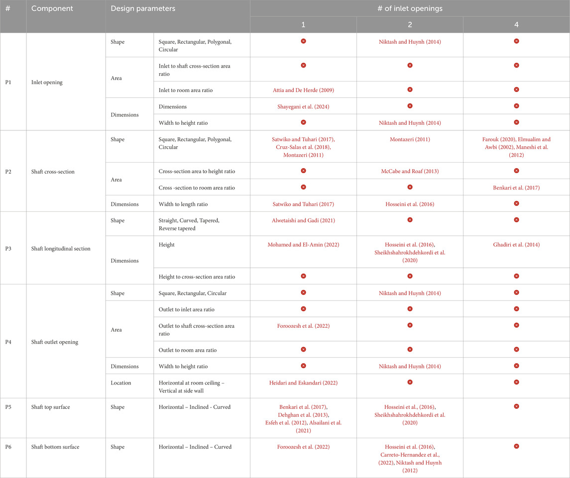
Table 2. Primary components and their design parameters coverage in scientific research.
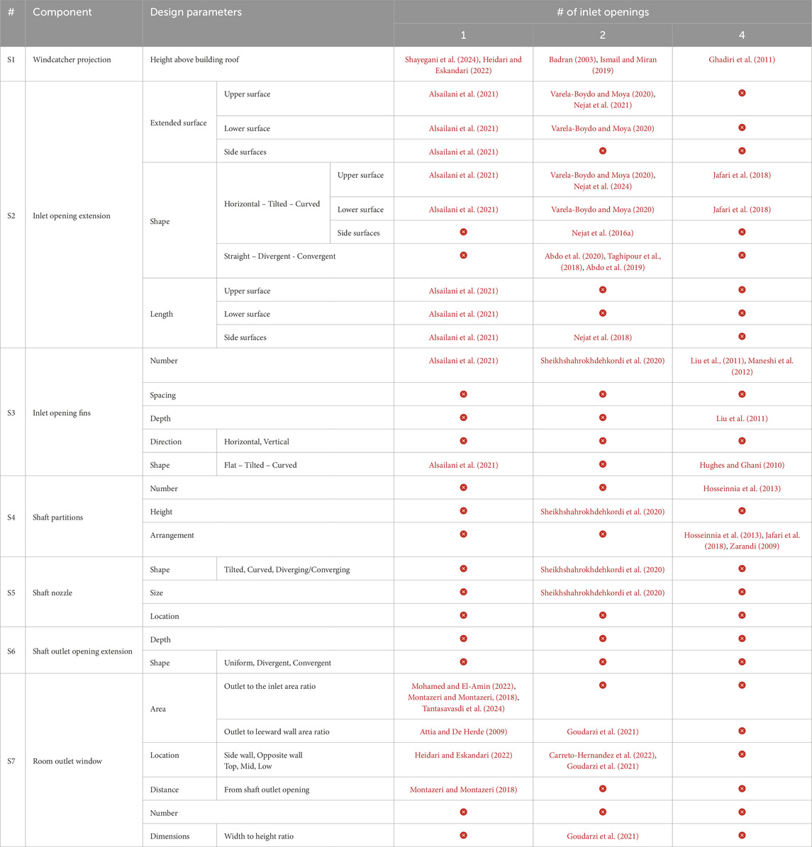
Table 3. Supplementary components and their design parameters coverage in scientific research.
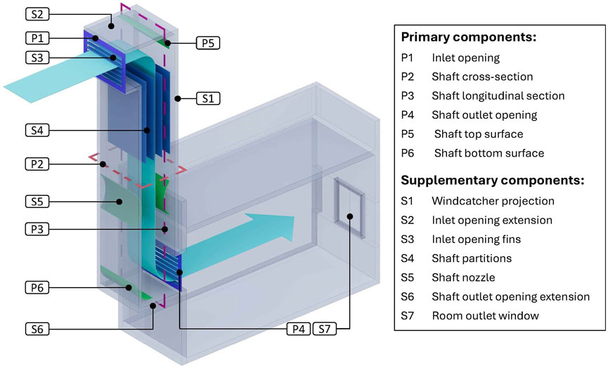
Figure 3. One-sided windcatcher design parameters status.
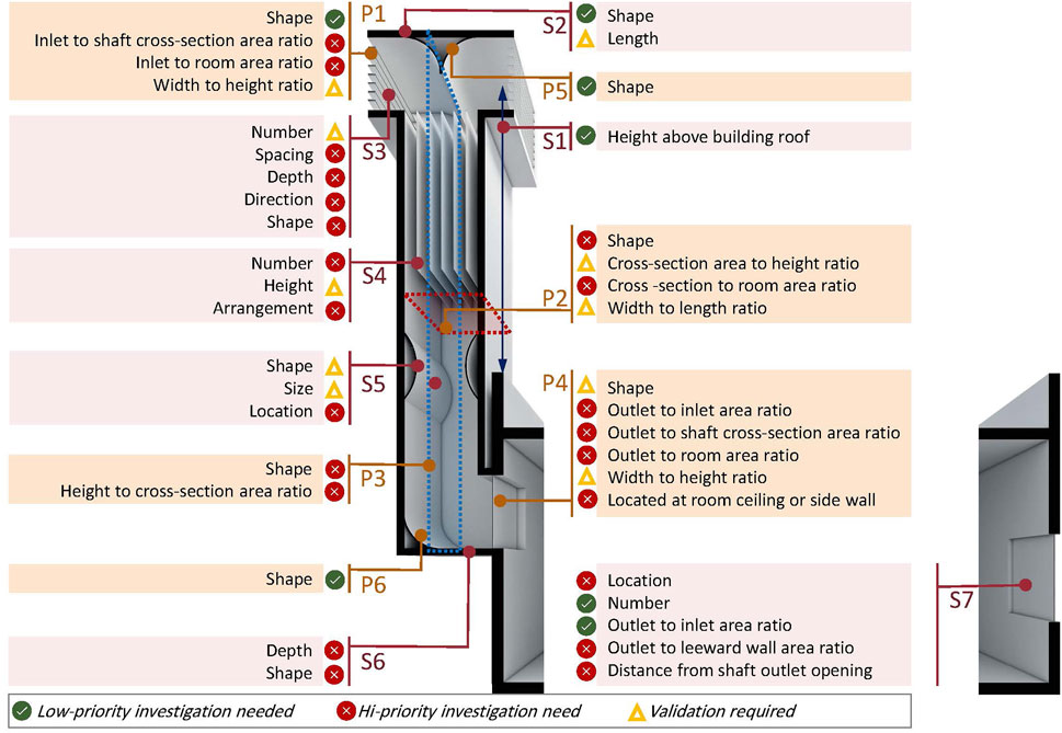
Figure 4. Two-sided windcatcher design parameters status.
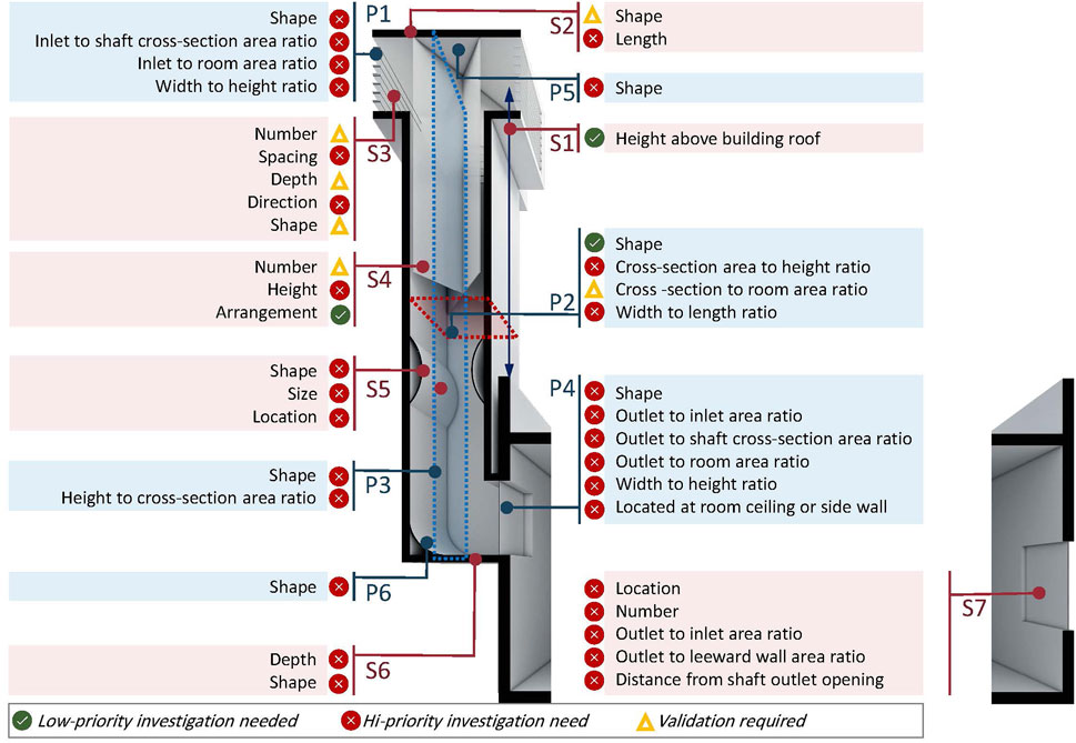
Figure 5. Four-sided windcatcher design parameters status.
Table 4 provides a summary of the experimental methods and climatic conditions employed in the reviewed studies. This information is crucial for understanding the variations observed in the design parameters of certain windcatcher components, as differences in testing conditions and methodologies can significantly influence the outcomes and performance metrics. By analyzing these factors, researchers can better interpret discrepancies and refine future investigations to ensure more consistent and reliable results.
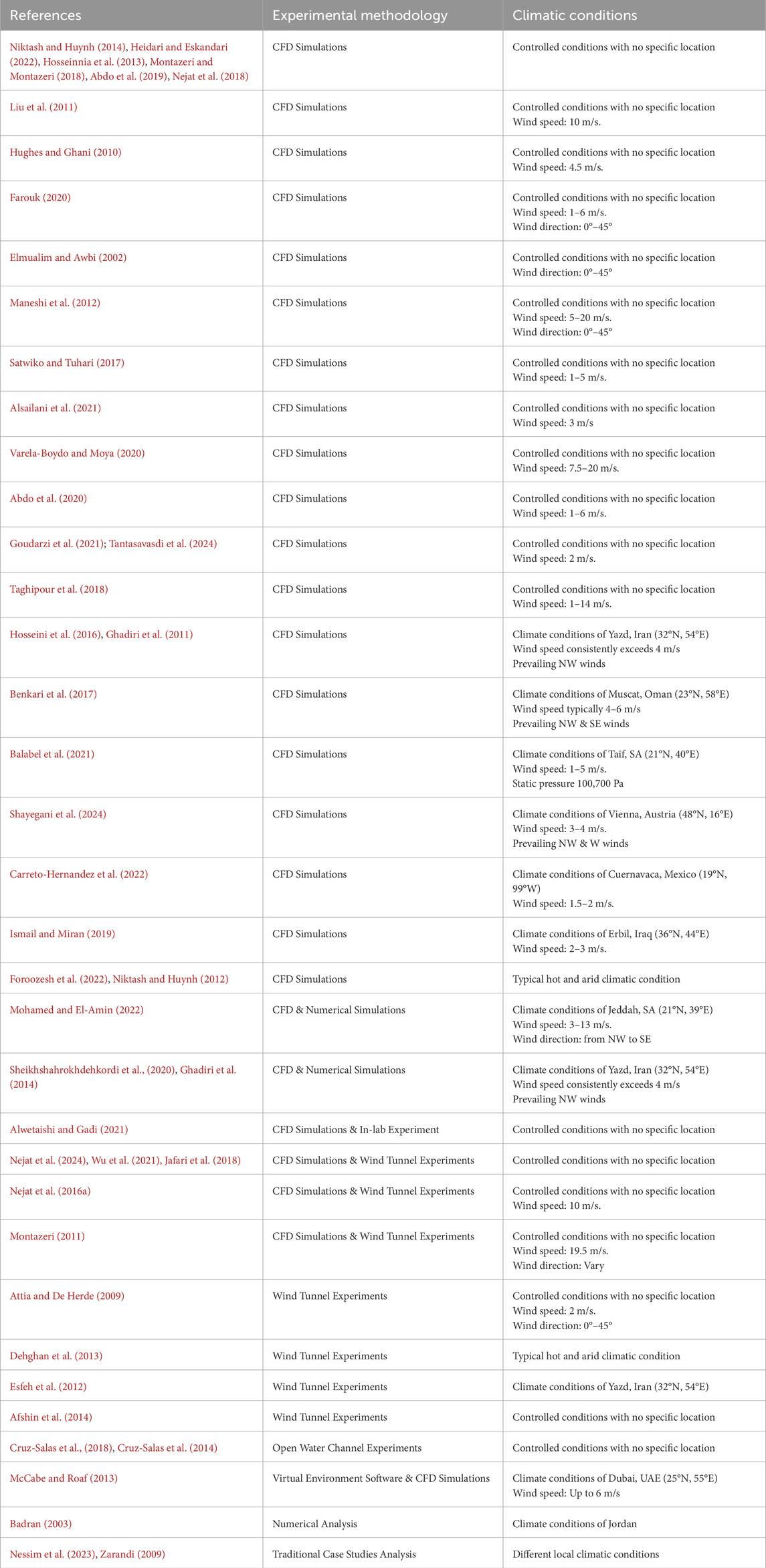
Table 4. Experimental methodologies and climatic conditions of windcatcher studies.
Regarding the projection height, while most recent studies recommend a projection height of 6–9 m, traditional Egyptian windcatchers typically have no projection above the roofline. This highlights the need for further research into the relationship between windcatcher projection height and different climatic conditions, as the optimal height may vary depending on environmental factors and regional airflow patterns.
Regarding the inlet openings, the recommended size—approximately 3% of the floor area of the ventilated space—is a crucial piece of information from an architectural design perspective. Given its significance as a key design parameter, it warrants high-priority further investigation to validate and ensure its accuracy across a wide range of conditions. The 3% value was derived from a wind tunnel experiment conducted at a wind speed of 2 m/s for a one-sided windcatcher (Attia and De Herde, 2009), which restricts its applicability. To establish reliability and adaptability for broader architectural applications, additional research is essential. This research should explore the performance of this guideline for different windcatcher types, under varying wind speeds, diverse climatic contexts, and different building configurations. Additionally, research showing that increasing the width-to-length ratio of rectangular openings enhances airflow also needs verification to ensure its practical applicability in various contexts. This finding was derived from a study focused on a two-sided windcatcher using CFD simulations under a limited range of climatic conditions (Niktash and Huynh, 2014). To ensure the generalizability of this recommendation, additional investigations cover a wider variety of windcatcher types, climatic conditions, and building environments are necessary.
The positive impact of upper extension of the inlet opening and wing walls on airflow efficiency has been established for two- and four-sided windcatchers, but their effectiveness in one-sided windcatchers needs further exploration. Researchers should focus on how variations in extension length and angle can be optimized for low- and high-wind scenarios. Moreover, the configurations of integrated fins within the inlet openings—such as blade size, spacing, number, direction, shape, and location—warrant additional study, particularly in one-sided windcatchers. Lastly, while the divergent extension configuration has demonstrated superior performance in two-sided windcatchers, its impact on other windcatcher types remains an open area for further research.
For the shaft cross-section, the length-to-width ratio of rectangular shafts has shown promising results; however, further research is necessary to determine the precise or optimal range for this ratio. More importantly, from an architectural design perspective, it is essential to identify the effective cross-sectional area relative to the size of the ventilated room.
While shaft partitions and nozzles have improved performance in traditional windcatcher designs, additional research is required to explore how these elements can be effectively incorporated into contemporary designs. This could involve testing various partition configurations, such as their layout, spacing, and height in relation to the shaft height. Similarly, further investigation is needed to optimize the design and placement of nozzles within the shaft, as well as to assess whether nozzles and partitions can be used simultaneously to enhance airflow, or if any conflicting effects may arise.
For the shaft height, no studies have recommended windcatcher heights exceeding three stories. Given the height of contemporary architectural designs, additional solutions need to be explored to extend the effective height of windcatchers and expand their applicability. Potential approaches include the use of curved or tapered shafts, which may enhance performance at greater heights and enable windcatcher systems to be integrated into taller buildings.
The geometry of the shaft’s top and bottom has been proven to enhance the performance of one- and two-sided windcatchers. However, further research is needed to assess how these geometric modifications affect the performance of four-sided windcatchers, as their airflow dynamics may differ significantly.
Regarding the room outlet windows, current research shows that the ratio of the room outlet window to the inlet opening remains insufficiently addressed aspect. While some studies suggest that having an outlet window with an area approximately equal to the inlet opening leads to optimal airflow and efficient cross-ventilation, others indicate that increasing the size of the outlet window to 1.5 or even 2 times the size of the inlet can improve ventilation rates significantly. Furthermore, some research suggests that increasing the outlet-to-inlet ratio beyond 1:1 yields diminishing returns in airflow, while other studies claim that larger ratios continue to enhance performance. These findings are primarily based on CFD simulations conducted under wind speeds ranging between 2 m/s and 13 m/s (Mohamed and El-Amin, 2022; Montazeri and Montazeri, 2018; Tantasavasdi et al., 2024), as presented in Table 4. More comprehensive research is needed to resolve these disagreements and provide clearer guidance.
4.3 Windcatcher components design parameters
The review revealed that design parameter recommendations for windcatcher components can be classified into five categories:
A. Specific shape or location: This category refers to the identified shape or location of specific components. Research findings in this category are the most consistent. As shown in Table 5, the rectangular cross-section and the curved top surface of the shaft are the most recommended shapes in the literature, which simplifies and standardizes windcatcher design.
B. Absolute value: This refers to fixed dimensions determined through research or practice. For instance, it is recommended that the optimal projection height be approximately 6 m above the building roof. This approach provides generalizable values that can be widely applied or offers a range of values adaptable to various ventilated space parameters, surrounding contexts, and climatic conditions.
C. Aspect ratio: This approach determines the aspect ratio of a specific component, such as the length-to-width ration of the inlet or outlet openings.
D. Relative value to other component: This approach establishes proportions based on the dimensions of related components (e.g., length, area, height). For instance, it is recommended that the inlet opening size match the cross-sectional area of the shaft. This approach is widely recognized in the literature and assists designers in maintaining system efficiency, even when design parameters differ.
E. Relative value to room characteristic: This approach sets values based on the characteristics of the room being served, such as recommending that the inlet opening area be approximately 3% of the floor area of the room. This approach, though less commonly referenced in the literature, emphasizes the dimensions of the ventilated space as the primary design driver, ensuring that each space is fitted with a windcatcher tailored to its specific characteristics.
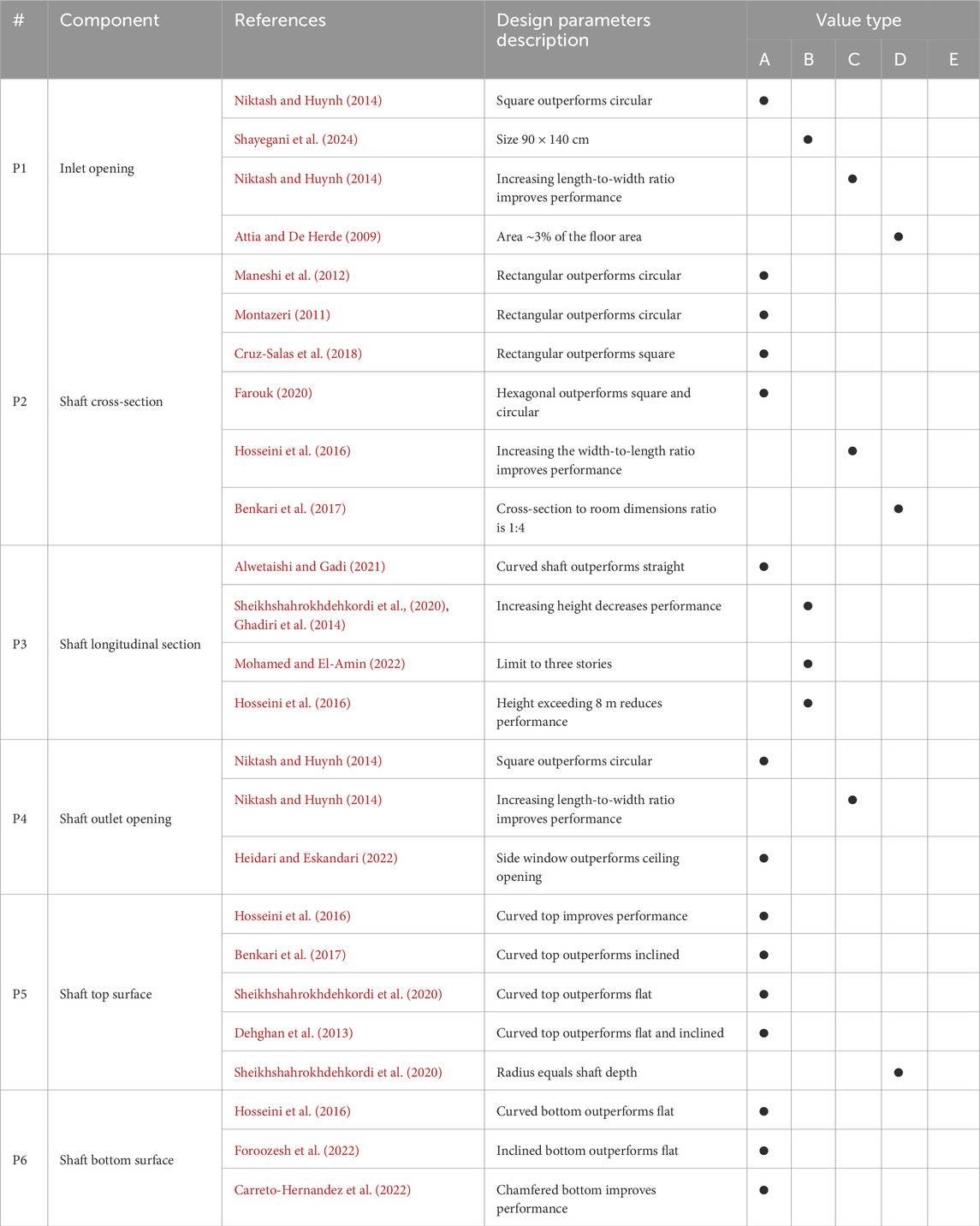
Table 5. Primary components design parameters.
For each approach, a distinct set of values can be established based on local climatic conditions. Researchers are encouraged to adopt the approach ‘E’, which focuses on producing guidelines tailored to the characteristics of the ventilated space, unless absolute values or relative values in relation to other components are proven to be universally applicable.
Tables 2, 3 summarize the design parameters of the primary and supplementary components, respectively, while Tables 5, 6 provide a detailed overview of the value and type for each design parameter. It is worth noting that all these values are derived from simulations or wind tunnel tests conducted on buildings with no surrounding obstacles. The setup of wind characteristics varies across the cases. It is evident that E-type values exhibit the most variation, such as the outlet-to-inlet ratio. This variability highlights the need to investigate and validate the influence of room-specific characteristics and the complexity of tailoring windcatcher designs to diverse spatial and environmental conditions.
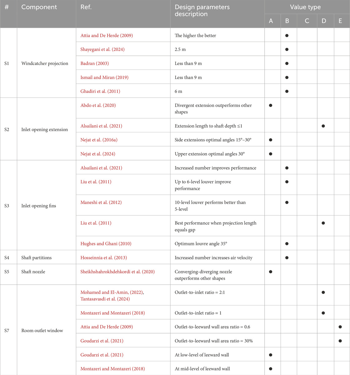
Table 6. Supplementary components design parameters.
5 Conclusion
Interest in windcatchers as a sustainable and energy-efficient natural ventilation system continues to grow, particularly in regions with hot and arid climates where cooling demands are high. However, incorporating windcatchers into contemporary architecture presents several challenges. A key difficulty lies in adapting traditional designs to meet modern architectural and environmental standards while maintaining performance. This highlights the urgent need for both a comprehensive design guide tailored to architects, a well-structured research roadmap to address existing knowledge gaps and inconsistencies, and standardized design parameters to establish a consistent body of knowledge.
The findings indicate that certain design parameters of windcatchers have been extensively studied, yielding consistent findings. For example, research on the shape of the windcatcher shaft’s cross-section and the top surface geometry has been thorough. Studies consistently show that rectangular cross-sections and curved shape of the shaft’s top surface outperform other shapes. These consistent findings provide architects with clear recommendations that can be confidently applied in most design scenarios, ensuring reliable windcatcher performance.
However, other aspects of windcatcher design remain insufficiently addressed, and inconsistent findings continue to pose challenges for architects and researchers alike. Addressing these issues should be a high priority for scholars in the field to resolve the existing ambiguities and advance understanding. A notable example is the ratio of the room outlet window to the inlet opening. While some studies suggest that the outlet window should be larger than the inlet to enhance airflow, others recommend a smaller outlet window for optimal cross-ventilation. This inconsistency makes it difficult to provide definitive design guidelines and highlights the need for further investigation.
Moreover, certain recommendations in the literature, though promising, still require further validation before they can be widely adopted. For instance, the suggestion that the area of the inlet opening should be approximately 3% of the floor area of the ventilated space is a crucial guideline from a design perspective. However, despite its importance, this recommendation has not yet been conclusively confirmed. Until such recommendation is rigorously tested and verified, architects must apply it with caution, recognizing that its effectiveness may vary depending on specific project conditions.
In addition to areas of inconsistency and unvalidated recommendations, certain crucial aspects of windcatcher design have been largely overlooked by researchers. One such area is the geometry of the shaft’s bottom surface. This lack of interest represents a significant gap in our understanding of windcatcher performance.
The application challenges and knowledge gaps highlighted above point to the urgent need for a detailed design guide specifically tailored for architects. Currently, architects face difficulty in making informed design decisions due to the fragmented nature of available data. A validated design guide would streamline this process, enabling the effective integration of windcatchers into building projects from the outset. Simultaneously, there is a pressing need for a research roadmap that directs future investigations toward underexplored aspects of windcatcher design. Research efforts to date have tended to focus disproportionately on certain design elements, while inconsistencies, uncertainty, and gaps in understanding remain in other areas.
The findings of this study indirectly influence contemporary architectural practices by exposing knowledge gaps in windcatcher design and identifying both well-researched and underexplored parameters. By highlighting these gaps, the study paves the way for future research and development, offering a roadmap to guide researchers in addressing these areas. This effort ultimately contributes to the creation of a comprehensive and reliable design guide that will enable architects to integrate windcatchers more effectively and widely into contemporary architecture, benefiting the broader architectural community.
Author contributions
MM: Conceptualization, Data curation, Formal Analysis, Investigation, Methodology, Visualization, Writing–original draft, Writing–review and editing. HS: Conceptualization, Funding acquisition, Investigation, Writing–review and editing. AA: Conceptualization, Funding acquisition, Project administration, Resources, Supervision, Writing–review and editing.
Funding
The author(s) declare that no financial support was received for the research and/or publication of this article.
Acknowledgments
Special thanks are extended to Eng. Mohamed Nagy and Eng. Esraa El. Rawy for their valuable assistance in the production of the figures.
Conflict of interest
The authors declare that the research was conducted in the absence of any commercial or financial relationships that could be construed as a potential conflict of interest.
Generative AI statement
The author(s) declare that Generative AI was used in the creation of this manuscript. During the preparation of this work the authors used ChatGPT in order to enhance language quality. After using this tool, the authors reviewed and edited the content as needed and take full responsibility for the content of the publication.
Publisher’s note
All claims expressed in this article are solely those of the authors and do not necessarily represent those of their affiliated organizations, or those of the publisher, the editors and the reviewers. Any product that may be evaluated in this article, or claim that may be made by its manufacturer, is not guaranteed or endorsed by the publisher.
References
Abdo, P., Taghipour, R., and Huynh, B. P. (2019). “Three dimensional simulation of the effect of windcatcher’s inlet shape,” ASME-JSME-KSME 2019 8th Joint Fluids Engineering conference.V002T02A028
Abdo, P., Taghipour, R., and Huynh, B. P. (2020). Three-dimensional simulation of wind-driven ventilation through a windcatcher with different inlet designs. J. Therm. Sci. Eng. Appl. 12 (4), 041008–041021. doi:10.1115/1.4045513
Afshin, M., Sohankar, A., Manshadi, M. D., Daneshgar, M., and Kamaragi, G. D. (2014). Visualized flow patterns around and inside a two-sided wind-catcher in the presence of Upstream structures. Int. J. Energy Power Eng. 8 (12), 1312–1317.
Alsailani, M., Montazeri, H., and Rezaeiha, A. (2021). Towards optimal aerodynamic design of wind catchers: impact of geometrical characteristics. Renew. Energy 168, 1344–1363. doi:10.1016/j.renene.2020.12.053
Alwetaishi, M., and Gadi, M. (2021). New and innovative wind catcher designs to improve indoor air quality in buildings. Energy Built Environ. 2 (4), 337–344. doi:10.1016/j.enbenv.2020.06.009
Attia, S. (2009). “Designing the Malqaf for summer cooling in low-rise housing, an experimental study,” in PLEA2009 - 26th conference on passive and low energy architecture. 22-24 June; Quebec, Canada.
Attia, S., and De Herde, A. (2009). “Designing the Malqaf for summer cooling in low-rise housing an experimental study,” Passive and low energy architecture (PLEA) (Quebec, Canada: Les Presses de l’Université Laval).
Badran, A. A. (2003). Performance of cool towers under various climates in Jordan. Energy Build. 35 (10), 1031–1035. doi:10.1016/s0378-7788(03)00067-7
Bahadori, M. N., Mazidi, M., and Dehghani, A. R. (2008). Experimental investigation of new designs of wind towers. Renew. Energy 33 (10), 2273–2281. doi:10.1016/j.renene.2007.12.018
Balabel, A., Alwetaishi, M., El-Askary, W. A., and Fawzy, H. (2021). Numerical study on natural ventilation characteristics of a partial-cylinder opening for one-sided-windcatcher of variable air-Feeding orientations in Taif, Saudi Arabia. Sustainability 13 (20), 11310. doi:10.3390/su132011310
Bekleyen, A., and Meli̇koğlu, Y. (2021). An investigation on the thermal effects of windcatchers. J. Build. Eng. 34, 101942. doi:10.1016/j.jobe.2020.101942
Benkari, N., Fazil, I., and Husain, A. (2017). Design and performance comparison of two patterns of wind-catcher for a semi-enclosed courtyard. Int. J. Mech. Eng. Robotics Res. 6 (5), 396–400. doi:10.18178/ijmerr.6.5.396-400
Boloorchi, H., and Eghtesadi, N. (2014). Investigation of the Middle East windcatchers and (comparison between windcatchers in Iran and Egypt in terms of components). Int. J. Archit. Urban Dev. 4, 87–94.
Calautit, J. K., O'Connor, D., and Hughes, B. R. (2014). Determining the optimum spacing and arrangement for commercial wind towers for ventilation performance. Build. Environ. 82, 274–287. doi:10.1016/j.buildenv.2014.08.024
Calautit, J. K., O'Connor, D., and Hughes, B. R. (2016). A natural ventilation wind tower with heat pipe heat recovery for cold climates. Renew. Energy 87, 1088–1104. doi:10.1016/j.renene.2015.08.026
Carreto-Hernandez, L. G., Moya, S. L., Varela-Boydo, C. A., and Francisco-Hernandez, A. (2022). Studies of ventilation and thermal comfort in different wind tower-room configurations considering humidification for a warm climate of Mexico. J. Build. Eng. 46, 103675. doi:10.1016/j.jobe.2021.103675
Chand, I., Sharma, V. K., and Krishak, N. L. V. (1990). Studies on the design and performance of wind catchers. Archit. Sci. Rev. 33 (4), 93–96. doi:10.1080/00038628.1990.9696682
Chohan, A. H., and Awad, J. (2022). Wind catchers: an element of passive ventilation in hot, arid and humid regions, a Comparative analysis of their design and function. Sustainability 14 (17), 11088. doi:10.3390/su141711088
Cruz-Salas, M. V., Castillo, J. A., and Huelsz, G. (2014). Experimental study on natural ventilation of a room with a windward window and different windexchangers. Energy Build. 84, 458–465. doi:10.1016/j.enbuild.2014.08.033
Cruz-Salas, M. V., Castillo, J. A., and Huelsz, G. (2018). Effect of windexchanger duct cross-section area and geometry on the room airflow distribution. J. Wind Eng. Industrial Aerodynamics 179, 514–523. doi:10.1016/j.jweia.2018.06.022
Dehghan, A. A., Esfeh, M. K., and Manshadi, M. D. (2013). Natural ventilation characteristics of one-sided wind catchers: experimental and analytical evaluation. Energy Build. 61, 366–377. doi:10.1016/j.enbuild.2013.02.048
Dehghani-sanij, A. R., Soltani, M., and Raahemifar, K. (2015). A new design of wind tower for passive ventilation in buildings to reduce energy consumption in windy regions. Renew. Sustain. Energy Rev. 42, 182–195. doi:10.1016/j.rser.2014.10.018
Elmualim, A. A. (2006). Effect of damper and heat source on wind catcher natural ventilation performance. Energy Build. 38 (8), 939–948. doi:10.1016/j.enbuild.2005.11.004
Elmualim, A. A., and Awbi, H. B. (2002). Wind tunnel and CFD investigation of the performance of “windcatcher” ventilation systems. Int. J. Vent. 1 (1), 53–64. doi:10.1080/14733315.2002.11683622
El-Shorbagy, A.-M. (2011). The future of windcatcher Malqaf -Part 5. Available online at: https://architecture.knoji.com/the-future-of-windcatcher-malqaf-part-5/.
Esfeh, M. K., Dehghan, A. A., Manshadi, M. D., and Mohagheghian, S. (2012). Visualized flow structure around and inside of one-sided wind-catchers. Energy Build. 55, 545–552. doi:10.1016/j.enbuild.2012.09.015
Farouk, M. (2020). Comparative study of hexagon & square windcatchers using CFD simulations. J. Build. Eng. 31, 101366.
Fathy, H. (1986). Natural energy and Vernacular architecture, principles and examples with reference to hot arid climates. Chicago: The United Nations University, The University of Chicago Press.
Fathy, H., and Abd-Elrahman, A. S. (1985). The Malqaf: a traditional cooling and ventilation system. Sunworld 9 (2), 48–62.
Foroozesh, J., Hosseini, S. H., Ahmadian Hosseini, A. J., Parvaz, F., Elsayed, K., Uygur Babaoğlu, N., et al. (2022). CFD modeling of the building integrated with a novel design of a one-sided wind-catcher with water spray: focus on thermal comfort. Sustain. Energy Technol. Assessments 53, 102736. doi:10.1016/j.seta.2022.102736
Ghadiri, M. H., Ibrahim, N. L. N., and Dehnavi, M. (2011). The effect of tower height in square plan wind catcher on its thermal behavior. Aust. J. Basic Appl. Sci. 5 (9), 381–385.
Ghadiri, M. H., Ibrahim, N. L. N., and Mohamed, M. F. (2013). Performance evaluation of four-sided square wind catchers with different Geometries by numerical method. Eng. J. 17 (4), 9–18. doi:10.4186/ej.2013.17.4.9
Ghadiri, M. H., Ibrahim, N. L. N., Mohamed, M. F., and Farid Mohamed, M. (2014). Applying computational fluid dynamic to evaluate the performance of four-sided rectangular wind catcher with different height. Res. J. Appl. Sci. Eng. Technol. 7 (3), 502–509. doi:10.19026/rjaset.7.282
Goudarzi, N., Sheikhshahrokhdehkordi, M., Khalesi, J., and Hosseiniirani, S. (2021). Airflow and thermal comfort evaluation of a room with different outlet opening sizes and elevations ventilated by a two-sided wind catcher. J. Build. Eng. 37, 102112. doi:10.1016/j.jobe.2020.102112
Heidari, A. A., and Eskandari, H. (2022). Impact of inlet and outlet opening height variation on the air quality and ventilation efficiency in the on-top wind catcher buildings: a CFD simulation. Sci. Technol. Built Environ. 28 (10), 1420–1438. doi:10.1080/23744731.2022.2089592
Heidari, S., Poshtiri, A. H., and Gilvaei, Z. M. (2024). Enhancing thermal comfort and natural ventilation in residential buildings: a design and assessment of an integrated system with horizontal windcatcher and evaporative cooling channels. Energy 289, 130040. doi:10.1016/j.energy.2023.130040
Hosseini, S. H., Shokry, E., Ahmadian Hosseini, A. J., Ahmadi, G., and Calautit, J. K. (2016). Evaluation of airflow and thermal comfort in buildings ventilated with wind catchers: simulation of conditions in Yazd City, Iran. Energy Sustain. Dev. 35, 7–24. doi:10.1016/j.esd.2016.09.005
Hosseinnia, S. M., Saffari, H., and Abdous, M. A. (2013). Effects of different internal designs of traditional wind towers on their thermal behavior. Energy Build. 62, 51–58. doi:10.1016/j.enbuild.2012.10.058
Hughes, B. R., Calautit, J. K., and Ghani, S. A. (2012). The development of commercial wind towers for natural ventilation: a review. Appl. Energy 92, 606–627. doi:10.1016/j.apenergy.2011.11.066
Hughes, B. R., and Ghani, SAAA (2010). A numerical investigation into the effect of Windvent louvre external angle on passive stack ventilation performance. Build. Environ. 45 (4), 1025–1036. doi:10.1016/j.buildenv.2009.10.010
Ismail, S. T., and Miran, F. D. (2019). The revival of traditional passive cooling techniques for school buildings through windcatchers. Int. Transaction J. Eng. Manag. & Appl. Sci. & Technol., 1–25.
Jafari, D., Shateri, A., and Ahmadi, N. A. (2018). Experimental and numerical study of natural ventilation in four-sided wind tower traps. Energy Equip. Syst. 6 (2), 167–179.
Jomehzadeh, F., Hussen, H. M., Calautit, J. K., Nejat, P., and Ferwati, M. S. (2020). Natural ventilation by windcatcher (Badgir): a review on the impacts of geometry, microclimate and macroclimate. Energy Build. 226, 110396. doi:10.1016/j.enbuild.2020.110396
Kahkzand, M., Deljouiee, B., Chahardoli, S., and Siavashi, M. (2024). Radiative cooling ventilation improvement using an integrated system of windcatcher and solar chimney. J. Build. Eng. 83, 108409. doi:10.1016/j.jobe.2023.108409
Khan, N., Su, Y., and Riffat, S. B. (2008). A review on wind driven ventilation techniques. Energy Build. 40 (8), 1586–1604. doi:10.1016/j.enbuild.2008.02.015
Li, J., Calautit, J., and Jimenez-Bescos, C. (2024). Parametric analysis of a novel rotary scoop dual-channel windcatcher for multi-directional natural ventilation of buildings. Energy Built Environ. doi:10.1016/j.enbenv.2024.07.002
Li, J., Calautit, J., Jimenez-Bescos, C., and Riffat, S. (2023a). Experimental and numerical evaluation of a novel dual-channel windcatcher with a rotary scoop for energy-saving technology integration. Build. Environ. 230, 110018. doi:10.1016/j.buildenv.2023.110018
Li, J., Calautit, J. K., and Jimenez-Bescos, C. (2023b). Experiment and numerical investigation of a novel flap fin louver windcatcher for multi-directional natural ventilation and passive technology integration. Build. Environ. 242, 110429. doi:10.1016/j.buildenv.2023.110429
Liu, M., Nejat, P., Cao, P., Jimenez-Bescos, C., and Calautit, J. K. (2024). A critical review of windcatcher ventilation: Micro-environment, techno-economics, and commercialisation. Renew. Sustain. Energy Rev. 191, 114048. doi:10.1016/j.rser.2023.114048
Liu, S., Mak, C. M., and Niu, J. (2011). Numerical evaluation of louver configuration and ventilation strategies for the windcatcher system. Build. Environ. 46 (8), 1600–1616. doi:10.1016/j.buildenv.2011.01.025
M. M. Maneshi, A. Rezaei-Bazkiaei, A. S. Weber, and G. F. Dargush (2012). A Numerical investigation of impact of architectural and climatic parameters of windcatcher systems on induced ventilation, Houston, TX (The American society for mechanical engineer (ASME) 2012 International Mechanical Engineering Congress and Exposition).
McCabe, C., and Roaf, S. (2013). The wind towers of Bastakiya: assessing the role of the towers in the whole house ventilation system using dynamic thermal modelling. Archit. Sci. Rev. 56 (2), 183–194. doi:10.1080/00038628.2012.723398
Mohamed, M. A. A., and El-Amin, M. F. (2022). Inward and Outward opening Properties of one-sided windcatchers: experimental and analytical evaluation. Sustainability 14 (7), 4048. doi:10.3390/su14074048
Monodraught Ltd (2017). Monodraught natural ventilation: Monodraught Ltd, UK. Available online at: https://www.monodraught.com/products/natural-ventilation.
Montazeri, H. (2011). Experimental and numerical study on natural ventilation performance of various multi-opening wind catchers. Build. Environ. 46 (2), 370–378. doi:10.1016/j.buildenv.2010.07.031
Montazeri, H., and Montazeri, F. (2018). CFD simulation of cross-ventilation in buildings using rooftop wind-catchers: impact of outlet openings. Renew. Energy 118, 502–520. doi:10.1016/j.renene.2017.11.032
Nejat, P., Calautit, J. K., Majid, M. Z. A., Hughes, B. R., and Jomehzadeh, F. (2016b). Anti-short-circuit device: a new solution for short-circuiting in windcatcher and improvement of natural ventilation performance. Build. Environ. 105, 24–39. doi:10.1016/j.buildenv.2016.05.023
Nejat, P., Calautit, J. K., Majid, M. Z. A., Hughes, B. R., Zeynali, I., and Jomehzadeh, F. (2016a). Evaluation of a two-sided windcatcher integrated with wing wall (as a new design) and comparison with a conventional windcatcher. Energy Build. 126, 287–300. doi:10.1016/j.enbuild.2016.05.025
Nejat, P., Fekri, Y., Sheikhshahrokhdehkordi, M., Jomehzadeh, F., Alsaad, H., and Voelker, C. (2024). The windcatcher: a Renewable-energy-Powered device for natural ventilation—the impact of upper wing walls. Energies 17 (3), 611. doi:10.3390/en17030611
Nejat, P., Jomehzadeh, F., Hussen, H. M., Calautit, J. K., and Abd Majid, M. Z. (2018). Application of wind as a renewable energy source for passive cooling through windcatchers integrated with wing walls. Energies 11 (10), 2536. doi:10.3390/en11102536
Nejat, P., Salim Ferwati, M., Calautit, J., Ghahramani, A., and Sheikhshahrokhdehkordi, M. (2021). Passive cooling and natural ventilation by the windcatcher (Badgir): an experimental and simulation study of indoor air quality, thermal comfort and passive cooling power. J. Build. Eng. 41, 102436. doi:10.1016/j.jobe.2021.102436
Nessim, M. A., Elshabshiri, A., Bassily, V., Soliman, N., Tarabieh, K., and Goubran, S. (2023). The rise and Evolution of wind tower designs in Egypt and the Middle East. Sustainability 15 (14), 10881. doi:10.3390/su151410881
Niktash, A., and Huynh, B. P. (2014). “Numerical simulation and analysis of the two-sided windcatcher Inlet\Outlet effect on ventilation flow through a three dimensional room,” ASME 2014 Power conference. V002T11A006.
Niktash, A. R., and Huynh, B. P. (2012). “Numerical analysis of ventilation flow through a three dimensional room fitted with a two-sided windcatcher,” in 18th Australasian Fluid Mechanics conference. Launceston, Australia2012.
Pelletier, K., and Calautit, J. (2022). Analysis of the performance of an integrated multistage helical coil heat transfer device and passive cooling windcatcher for buildings in hot climates. J. Build. Eng. 48, 103899. doi:10.1016/j.jobe.2021.103899
Saadatian, O., Haw, L. C., Sopian, K., and Sulaiman, M. Y. (2012). Review of windcatcher technologies. Renew. Sustain. Energy Rev. 16 (3), 1477–1495. doi:10.1016/j.rser.2011.11.037
Sadeghi, M., de Dear, R., Samali, B., and Wood, G. (2017). Optimization of wind tower cooling performance: a wind tunnel study of indoor air movement and thermal comfort. Procedia Eng. 180, 611–620. doi:10.1016/j.proeng.2017.04.220
Sangdeh, P. K., and Nasrollahi, N. (2022). Windcatchers and their applications in contemporary architecture. Energy Built Environ. 3 (1), 56–72. doi:10.1016/j.enbenv.2020.10.005
Satwiko, P., and Tuhari, M. T. (2017). The development of hybrid longitudinal windcatcher for basement ventilation in warm humid climate. Int. J. Vent. 16 (1), 15–29. doi:10.1080/14733315.2016.1252148
Shayegani, A., Joklova, V., and Illes, J. (2024). Optimizing windcatcher designs for effective passive cooling strategies in Vienna’s urban environment. Buildings 14 (3), 765. doi:10.3390/buildings14030765
Sheikhshahrokhdehkordi, M., Khalesi, J., and Goudarzi, N. (2020). High-performance building: Sensitivity analysis for simulating different combinations of components of a two-sided windcatcher. J. Build. Eng. 28, 101079. doi:10.1016/j.jobe.2019.101079
Soltani, M., Dehghani-Sanij, A., Sayadnia, A., Kashkooli, F. M., Gharali, K., Mahbaz, S., et al. (2018). Investigation of airflow patterns in a new design of wind tower with a wetted surface. Energies 11 (5), 1100. doi:10.3390/en11051100
Suleiman, S., and Himmo, B. (2012). Direct comfort ventilation. Wisdom of the past and technology of the future (wind-catcher). Sustain. Cities Soc. 5, 8–15. doi:10.1016/j.scs.2012.09.002
Taghipour, R., Abdo, P., and Huynh, B. P. (2018). Effect of wind speed on ventilation flow through a two dimensional room fitted with a windcatcher. ASME 2018 International mechanical Engineering Congress and Exposition. V007T09A023.
Tantasavasdi, C., Arttamart, S., and Inprom, N. (2024). Combined wind catchers and side windows for cross ventilation in row houses. J. Eng. Des. Technol. doi:10.1108/jedt-02-2023-0079
Varela-Boydo, C. A., and Moya, S. L. (2020). Inlet extensions for wind towers to improve natural ventilation in buildings. Sustain. Cities Soc. 53, 101933. doi:10.1016/j.scs.2019.101933
Varela-Boydo, C. A., Moya, S. L., and Watkins, R. (2021). Analysis of traditional windcatchers and the effects produced by changing the size, shape, and position of the outlet opening. J. Build. Eng. 33, 101828. doi:10.1016/j.jobe.2020.101828
Wu, Y., Gao, N., Niu, J., Zang, J., and Cao, Q. (2021). Numerical study on natural ventilation of the wind tower: effects of combining with different window configurations in a low-rise house. Build. Environ. 188, 107450. doi:10.1016/j.buildenv.2020.107450
Keywords: windcatcher, natural ventilation, geometrical design parameters, primary components, supplementary components, wind tower
Citation: Mayhoub M, Selim H and Abuzaid A (2025) Roadmap to developing a geometrical design guide for windcatchers. Front. Built Environ. 11:1534284. doi: 10.3389/fbuil.2025.1534284
Received: 25 November 2024; Accepted: 03 March 2025;
Published: 20 March 2025.
Edited by:
Roberto Alonso González-Lezcano, CEU San Pablo University, SpainReviewed by:
Marilena Musto, University of Naples Federico II, ItalySofia Melero-Tur, CEU San Pablo University, Spain
Copyright © 2025 Mayhoub, Selim and Abuzaid. This is an open-access article distributed under the terms of the Creative Commons Attribution License (CC BY). The use, distribution or reproduction in other forums is permitted, provided the original author(s) and the copyright owner(s) are credited and that the original publication in this journal is cited, in accordance with accepted academic practice. No use, distribution or reproduction is permitted which does not comply with these terms.
*Correspondence: Mohammed Mayhoub, bXNtQGF6aGFyLmVkdS5lZw==; Haitham Selim, aHNlbGltQG9jLmVkdS5zYQ==