 Liang Cao
 Thomas M. Marullo
 James Michael Ricles
 Richard Sause
 Claudia Reis
 Joseph Saunders
- 1ATLSS Engineering Research Center, Lehigh University, Bethlehem, PA, United States
- 2Department of Civil and Environmental Engineering, Lehigh University, Bethlehem, PA, United States
Natural hazards, including hurricanes and earthquakes, can escalate into catastrophic societal events due to the destruction of the built environment. To minimize the impact of such hazards on vulnerable communities, civil infrastructure must be designed with performance criteria that prioritize public safety and ensure continuous operation. The National Science Foundation funded Natural Hazards Engineering Research Infrastructure (NHERI) program focuses on advancing the development of resilient infrastructure. The NHERI Lehigh Real-time Multi-directional Simulation Experimental Facility (EF) is one of the facilities within this program. The facility serves as an open-access research hub, offering advanced technologies and engineering tools to develop innovative solutions for natural hazard mitigation. It is uniquely equipped to perform large-scale, multi-directional structural testing in real-time using a cyber-physical simulation technique known as real-time hybrid simulation. This technique enables researchers to model entire systems subjected to dynamic loads at a full scale, allowing for realistic assessments of infrastructure responses to specific hazard scenarios and the development of effective mitigation strategies. This paper explores how cyber-physical simulation has revolutionized research in natural hazards engineering and its influence on engineering practices. It highlights several ongoing projects at the NHERI Lehigh EF aimed at enhancing community resilience in hazard-prone regions. The paper also discusses the planned expansion of the EF, which aims to broaden its focus to include a wider range of natural hazards, and infrastructure systems. This expansion will incorporate both physical and computational resources to enhance the understanding of fluid interactions in combined natural hazards and climate change impacts on coastal and offshore infrastructure. The NHERI Lehigh EF represents a transformative facility that is reshaping natural hazards research and will continue to play a pivotal role in the development of risk management strategies for more resilient communities.
1 Introduction
The Natural Hazards Engineering Research Infrastructure (NHERI) Lehigh Experimental Facility (EF), known as the Real-Time Multi-Directional (RTMD) Hybrid Simulation Facility, operates in the Multi-Directional Testing Laboratory at Lehigh University’s Advanced Technology for Large Structural Systems (ATLSS) Engineering Research Center. Supported by the NHERI program funded by the National Science Foundation (NSF), the NHERI Lehigh EF provides an open access facility for researchers to use advanced technologies and engineering tools to develop natural hazards mitigation solutions. The facility has a unique portfolio of equipment, instrumentation, infrastructure, testbeds, experimental simulation control protocols, and large-scale simulation and testing capabilities. Various testbeds exist at the NHERI Lehigh EF for researchers to explore civil infrastructure response and develop resilient solutions to enhance infrastructure performance to natural hazards. These include: (1) a lateral load resisting system characterization large-scale testbed; (2) a non-structural component multi-directional dynamic loading large-scale simulator; (3) full-scale damper testbeds; (4) a tsunami debris impact force testbed; (5) soil-foundation structure interaction testbeds; and, the (6) NHERI Lehigh Real-time Cyber-Physical Structural Systems (RCPSS) simulation laboratory.
The NHERI Lehigh EF has the unique ability to conduct large-scale multi-directional structural testing in real-time using a cyber-physical simulation approach, also known as real-time hybrid simulation (RTHS). RTHS integrates the benefits of numerical simulations and physical tests by dividing the structure system into analytical and experimental substructures. In an RTHS, well-understood structural components are modeled numerically in the computer as the analytical substructure, with the remaining components physically modeled using an experimental substructure. The two substructures are coupled in real time by imposing interface displacements and enforcing equilibrium between the substructures. This type of testing and other forms of simulations that can be performed at the NHERI Lehigh EF include: (1) large-scale hybrid simulation (HS) which combines large-scale physical models with computer-based numerical simulations (Lin et al., 2013); (2) large-scale RTHS which is a HS conducted at the actual time scale of the physical models and excitations (Chen et al., 2009; Karavasilis et al., 2011; Chae et al., 2014; Dong et al., 2015); (3) large-scale RTHS with real-time online model updating where some of complex components are physically tested in the laboratory and others are numerically modeled with real-time online model updating (Al-Subaihawi et al., 2022; 2024a); (4) large-scale RTHS with multiple experimental substructures where several experimental specimens are used in a RTHS (Chen and Ricles, 2012; Al-Subaihawi et al., 2020); (5) geographically distributed HS where physical models and/or numerical simulation models are located in different laboratories and connected through the internet (Ricles et al., 2007); (6) geographically distributed RTHS (Kim et al., 2012); (7) quasi-static testing of physical models using predefined force or displacement histories (Zhang and Ricles, 2006; Ricles et al., 2002b; Perez et al., 2013); (8) high-speed testing using servo-controlled hydraulic dynamic actuators at real-time scales to impose predefined force or displacement histories (Ricles et al., 2002a; Chae et al., 2013b); (9) multi-axis RTHS shake table tests with physical models placed on a multi-directional shake table (Villalobos Vega et al., 2022); and (10) multi-physics RTHS with numerical models accounting for soil-structure-interaction or fluid-structure-interaction effects (Al-Subaihawi et al., 2024). The NHERI Lehigh EF enhances the NHERI network by offering complementary testing capabilities to support the diverse experimental needs of the research community. For example, wind pressures measured at a wind tunnel facility (i.e., NHERI Florida International University (Azzi et al., 2020) or the University of Florida Facilities (Catarelli et al., 2020)), wave loads measured at a wave flume (i.e., NHERI Oregon State University Facility (Lomonaco et al., 2020)) can be used for a multi-physics RTHS conducted at the NHERI Lehigh EF. All test results and research data are shared through the NHERI DesignSafe Data Depot Repository (Rathje et al., 2017).
Several experimental research projects have been performed using the equipment and algorithms at the NHERI Lehigh EF, including: (1) multi-directional RTHS of a tall building equipped with nonlinear viscous dampers subjected to earthquake and wind hazards (Al-Subaihawi et al., 2024a); (2) multi-physics RTHS of a tall building with a soil-foundation system modeled using neural networks and subjected to wind hazards (Al-Subaihawi et al., 2024); (3) 3D RTHS using a multi-axis shake table to test floor isolation systems for mitigating detrimental seismic effects on critical building contents (Villalobos Vega et al., 2024); (4) multi-directional cyclic lateral loading tests of self-centering cross-laminated mass timber shear wall sub-assembly (Amer et al., 2024); and, (5) large scale tests of seismic collectors in a steel frame floor system. Discoveries from these projects illustrate the important aspects of large-scale, multi-directional, real-time hybrid testing with multi-physics effects for the development of innovative resilient structural systems that contain new natural hazard mitigation strategies.
The paper is organized into five remaining sections. Section 2 presents an overview of the NHERI Lehigh EF, including the team members and their expertise, equipment, testbeds, real-time integrated control system and testing capabilities. Section 3 presents the protocol for performing real-time cyber-physical simulations at the facility. Section 4 describes recent research projects conducted at the NHERI Lehigh EF and their respective contributions towards creating a more natural-hazards resilient community. A summary and conclusions are given in Section 5.
2 Overview of the NHERI Lehigh EF
This section provides an overview of the NHERI Lehigh EF, including its unique expertise of the staff, equipment, testbeds, real-time control integrated system and testing capabilities. The unique strengths of the facility’s equipment, testbeds, control system, and staff expertise enable a wide range of simulations and types of testing. These include: (1) large-scale HS; (2) large-scale RTHS; (3) large-scale RTHS with real-time online model updating; (4) large-scale RTHS with multiple experimental substructures; (5) geographically distributed HS; (6) geographically distributed RTHS; (7) quasi-static testing; (8) dynamic testing; (9) multi-directional RTHS multi-axis shake table tests; and (10) multi-physics RTHS. In addition, multiple simulations and tests can be performed simultaneously, allowing numerous users to work concurrently without significant interruption.
2.1 NHERI Lehigh EF team and expertise
The NHERI Lehigh EF is highly dependent on its staff who are dedicated to supporting the operations of the facility. Figure 1 shows the NHERI Lehigh EF staff members and the capacity building advisory council, and lists their main expertise in multidisciplinary and complementary research fields associated with natural hazards engineering.

Figure 1. NHERI Lehigh EF staff and capacity building council.
The ATLSS Engineering Research Center and the NHERI Lehigh EF are led by Dr. James Ricles, who provides overall leadership and accountability for completing the missions of the ATLSS Center and NHERI Lehigh EF. Dr. Richard Sause and Dr. Claudia Reis, associate directors, provide leadership support and technical assistance to the Director, Dr. James Ricles. The expertise of Dr. James Ricles includes RTHS as well as large-scale computational and experimental simulation, while the expertise of Dr. Richard Sause includes performance-based engineering and resilient structural system concepts. Dr. Claudia Reis’ expertise includes hyrodynamics and fluid-structure interaction, along with risk mitigation of coastal civil infrastructure. Research scientist Thomas Marullo oversees the facility’s IT systems along with the development and implementation of software and algorithms to support testing protocols. Research scientist Dr. Liang Cao supervises the configurations of the experimental protocol, user training, and site improvements. Dr. Joseph Saunders manages the facility’s operations and is responsible for the education, communication, and outreach program. Darrick Fritchman manages a team of highly skilled technicians who provide laboratory support for research projects. The skills sets of laboratory technicians include servo-hydraulics, instrumentation, fabrication, and erection of test specimens. The capacity building advisory council of the NHERI Lehigh EF is composed of Lehigh faculty who possess complementary expertise and provide capacity-building advice. Dr. Shamim Pakzad provides technical capacity building advice in the areas of advanced sensors and structural health monitoring. Dr. Muhannad Suleiman provides technical capacity-building advice in soil-structure interaction and geotechnical engineering. Dr. Keith Moored provides technical capacity-building advice in the area of aerodynamics and bio-inspired engineering innovations applied to natural hazards mitigation, while Dr. Paolo Bocchini provides technical capacity-building support in the areas of probabilistic modeling and infrastructure resilience.
The highly skilled multidisciplinary team members, laboratory technicians, and capacity-building advisory council enable the acquisition of high-quality numerical and experimental results through complex simulations and tests performed at the NHERI Lehigh EF.
2.2 NHERI Lehigh EF equipment
The NHERI Lehigh EF is located within the ATLSS Engineering Research Center that has 2,736
2.3 NHERI Lehigh EF testbeds
Various large-scale testbeds are available at the NHERI Lehigh EF. Details of these test beds can be found in (Cao et al., 2020) describing: (1) an 11 m wide by 13.7 m high lateral load resisting system characterization testbed; (2) a 3 m wide by 12 m long non-structural component multi-directional dynamic loading simulator; (3) full-scale damper testbeds with five large-scale dynamic actuators; (4) a tsunami debris impact force testbed; and (5) a soil-foundation-structure interaction testbed with two large-scale soil boxes. These testbeds provide a wide range of large-scale testing capabilities that include quasi-static and dynamic testing in addition to HS. Researchers can use these testbeds to perform multi-directional experimental investigations on large-scale structural components and systems, in addition to non-structural components subjected to extreme natural hazard events that include soil-foundation effects.
2.3.1 NHERI Lehigh real-time cyber-physical structural systems testing laboratory
In addition to large-scale testing capabilities, the NHERI Lehigh EF recently features a 372
The dynamic testbeds in the RCPSS can accommodate a broad range of dynamic characterization and HS natural hazards experiments for researchers to explore structural mitigation solutions. In each testbed, an MTS dynamic servo-hydraulic actuator and test specimen can be placed. A 32 channel high speed data acquisition system and an array of sensors are available to measure displacement, rotation, temperature, acceleration, strain, and force to acquire measured test data.
For example, a setup for testing a next-generation 45 kN capacity semi-active rotary friction damper (Downey et al., 2016) in the RCPSS testing lab is shown in Figure 2A. The test setup consists of an actuator mounted on a foundation beam, with a reaction support (identified as column support) and the rotary friction damper connected to a hydraulic actuator via a roller support. The damper forces applied by the actuator are measured with a load cell, safety relays are incorporated into the test setup to provide safety measures and protection of the test specimens. The testbed has been used to perform various dynamic characterization and RTHS tests (Cao et al., 2024; Coble et al., 2024). The results of these studies show that the rotary friction damper has a dynamic amplification factor of 110, requiring smaller amounts of energy to develop the frictional force compared to conventional friction dampers. This rotary friction damper is therefore a feasible device that can be used to create effective multi-hazard mitigation solutions for reducing damage to civil infrastructure during extreme natural hazard events.
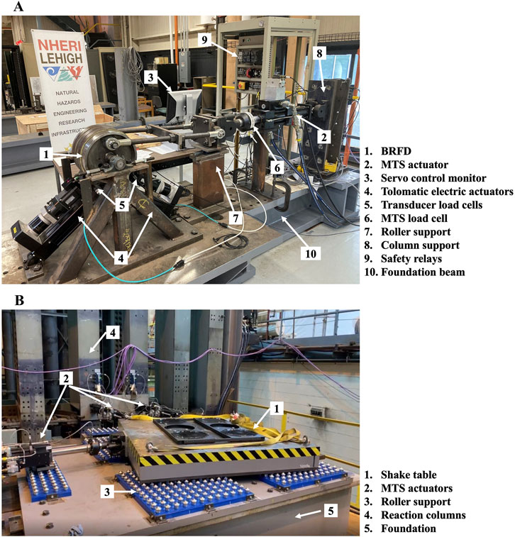
Figure 2. NHERI Lehigh RCPSS Testing Laboratory: (A) Dynamic test setup of a rotary friction damper; (B) Real-time cyber-physical structural systems multi-directional shake table (multi-directional translation and torsional in-plane motion applied).
The RCPSS testing laboratory also includes a Real-time Cyber-Physical Structural Systems Multi-directional Shake Table. This shake table has a table platen size of 1829 mm
Figure 2B shows a photograph of the multi-directional shake table with multi-directional translation and torsional motion applied in the plane. The shake table can be used in different configurations to perform a range of experiments, including real-time multi-axis shake table hybrid simulations, traditional multi-axis shake table testing, or used as a load platen to perform quasi-static and dynamic testing of test specimens.
2.4 NHERI Lehigh EF integrated control system
The NHERI Lehigh EF real-time testing architecture features a real-time integrated control system enabling both real-time and paced control of multi-directional testing. A schematic of the real-time testing architecture is shown in Figure 3. The real-time integrated control system architecture consists of various systems that are linked by Ethernet and SCRAMNet GT communication hardware. SCRAMNet GT is a shared memory fiber optic based network that synchronizes data among a ring of systems thus facilitating experimental protocols and access to data in real time. Synchronization over SCRAMNet GT is enforced by the Servotest Pulsar servo hydraulic controller which has a clock speed of 2048 Hz. The servo hydraulic controller is identified as RTMDctrl in Figure 3. The controller operates tunable closed-loop PID control algorithms for each actuator and has I/O controls for managing the hydraulic power system. External control over SCRAMNet GT is enabled and feedback data such as position and force responses from each actuator is written to SCRAMNet GT at the control rate. High fidelity data acquisition is capable through the Pacific Instruments 6,000 series data acquisition system, known as RTMDdaq.
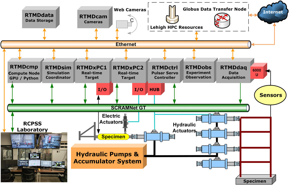
Figure 3. NHERI Lehigh RTMD EF real-time testing integrated control system architecture.
The algorithms necessary to execute the experimental protocols are implemented through the Simulation PC workstation, known as RTMDsim. The algorithms are tailored specifically for each test and programmed primarily using MATLAB and Simulink. Simulink is used to design a model-in-the-loop system that can interact with the servo hydraulic controller and data acquisition system over SCRAMNet GT. To execute these models, they are compiled and deployed to Speedgoat Real-time Performance Systems, known as RTMDxPC1 and RTMDxPC2. These standalone, robust embedded systems run a unique real-time operating system that is designed to execute compiled Simulink models and interact with various supported hardware typically at a simulation rate of 1,024 Hz. If a simulation requires a large computational model with many degrees of freedom, or there is a need for additional hardware communications such as controlling electric and hydraulic actuators simultaneously, then the executable code is parallelized and placed onto multiple xPC systems, i.e., RTMDxPC1 and RTMDxPC2.
For models that exceed the capabilities of the xPC computational limit such as large matrix multiplications, the GPU workstation RTMDcmp is available for additional high-performance processing. This system is an Intel based i9 CPU and contains an NVIDIA RTX 4000 series GPU along with SCRAMNet GT. Python is the preferred programming architecture executed on this system and is available during real-time simulation. It can also be used for using machine learning to train neural network models and for post processing of test results.
The PC workstation RTMDcam is configured with Blue Iris video management software that is capable of configuring, recording and synchronizing web camera video and images along with providing a web interface for users. The PC workstation RTMDobs has audio and video capabilities and can be used to observe data, plot feedback signals, and interact with remote users via telepresence software such as Zoom. For RTHS, MATLAB-based software is available to animate the real-time response of a complete system, including the analytical and experimental substructures. Experimental data, metadata and training materials are organized and archived on a Synology dual disk redundancy network attached storage system known as RTMDdata. As noted in Figure 3, there is a twin lab known as the RCPSS laboratory with the same real-time integrated control architecture and is directly connected to the RTMD laboratory through SCRAMNet GT and Ethernet. Both laboratories have identical capabilities and allow users to perform experiments simultaneously using multiple testbeds.
3 NHERI Lehigh EF real-time cyber-physical simulation
This section outlines the key approach of the NHERI Lehigh EF, emphasizing real-time cyber-physical simulation, as well as advancements in multi-directional and multi-physics RTHS.
3.1 Overall concept of RTHS
A schematic showing the process for performing an RTHS is given in Figure 4A. The RTHS is governed by the equations of motion, namely:
where
For a given time step
Referring to Figure 4A, for an applied loading
3.2 Development for multi-directional RTHS
To conduct RTHS on structures subjected to multi-directional natural hazards, termed multi-directional RTHS, three-dimensional nonlinear models of structural systems are required. The NHERI Lehigh EF staff has developed the MATLAB and Simulink-based finite element program HyCoM-3D, (Ricles et al., 2020), for assessing the multi-directional performance of civil infrastructure systems. HyCoM-3D is a three-dimensional (3D) simulation program that is compatible with the xPCs of the real-time integrated control system. The program has nonlinear geometric and material modeling capabilities. It contains a material library for modeling structural steel, reinforced concrete, timber, nonlinear viscous, shape memory alloy, and friction materials. The explicit-formulated element library in HyCoM-3D includes nonlinear truss elements, displacement-based and force-based fiber elements with co-rotational geometric and material nonlinearities, nonlinear geometric elements to model P-
3.3 Extension to multi-physics RTHS
In nature, the effects of natural hazards on infrastructure systems represent complex multi-physics interactions. In inland locations, these interactions encompass soil-foundation-structure systems while in coastal and offshore regions, the system is subjected to wave-wind-soil-structure interaction effects.
The NHERI Lehigh EF recently implemented a new framework for incorporating soil-foundation-structure interactions (SFSI), enabling realistic simulations of inland systems. The overall concept of multi-physics RTHS is demonstrated using an example of an SFSI system equipped with passive nonlinear viscous dampers subjected to wind loads, as shown in Figure 4B. The structural system is a 40-story steel frame building, with nonlinear passive viscous dampers installed in outrigger trusses to improve its performance under natural hazards. Structural components that include steel frames, associated seismic mass, and inherent damping are numerically modeled using the finite element method, while the soil and foundation beneath the building are modeled using a real-time neural network (NN) model.
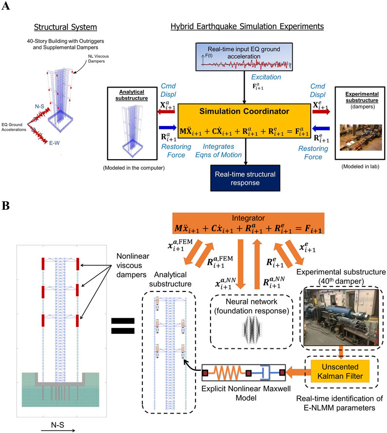
Figure 4. (A) Schematic of the RTHS process; (B) Multi-physics RTHS example: a 40-story building with soil-structure interaction using neural network (courtesy of Al-Subaihawi et al. (2024)).
The analytical substructure consists of the structure, soil, and foundation models, while the nonlinear viscous dampers are physically modeled in the laboratory as the experimental substructure. Multi-directional earthquake loads are determined from the accelerograms of ground motions. More details are described in Section 4.2. The equations of motion are augmented with the NN model’s degrees of freedom and therefore,
For fluid-soil-structure interactions (FSSI) characteristic of coastal and offshore environments, it is necessary to acknowledge an increased complexity, not only from the physical phenomena, but also because the FSSI system becomes a multi-physics problem. One of the major challenges is to model the behavior of the fluid and the solids in the same domains. Moreover, as they are governed by different laws of physics, it is preferable to use full-scale models to avoid similitude issues. Another challenge is the computational costs deemed necessary to achieve high fidelity numerical solutions realistically reproducing highly nonlinear FSSI phenomena. In addition, there is a lack of field and experimental data of structural compliance within mild to turbulent flows to calibrate and validate the simulation models.
Thus, the NHERI Lehigh EF is developing two complementary approaches to test FSSI of infrastructure subjected to hydraulic loads. The first approach consists of a numerical characterization of the fluid behavior that is imposed on a physical structure or soil-structure system. The numerical models rely on sophisticated numerical schemes capable of modeling two-way fluid-solid interactions. Before their use, these numerical schemes are being subjected to an exhaustive benchmark test using data recorded during experimental campaigns. Given the computational demand inherent to such models, the use of machine learning models, such as the NN models previously adopted to model SFSI, represents a useful tool. In this case, the fluid behavior is numerically computed from the classic fluid model to train the NN model. The trained NN model is then used to impose the fluid loading on the structure, which can be imposed on the experimental structure using as many actuators as needed to account for the multi-degree of freedom nature of the problem.
The second approach is utilizing a wave flume to physically model fluid mechanics in an FSSI RTHS framework. The wave flume will be incorporated into the RTHS framework to complement an existing experimental setup consisting of structural and soil-foundation systems. Complex, multi-physics systems can be modeled by coupling physical setups in Simulink to create a model-in-the-loop system, which is then compiled and deployed to real-time systems. In addition, the wave flume will produce experimental data to calibrate and validate numerical, and machine learning models. Details on the expansion of the NHERI Lehigh EF will be published soon.
4 Developments and discoveries from recent research projects
In this section, five selected example projects performed by researchers that utilized the NHERI Lehigh EF are presented. These example projects leveraged the NHERI Lehigh EF resources to conduct large-scale, multi-directional, and multi-physics experiments. The outcomes and impact of these studies on natural hazards engineering are highlighted, showcasing the benefits of utilizing the NHERI Lehigh EF.
4.1 Multi-directional RTHS of a tall building equipped with nonlinear viscous dampers subjected to natural hazards
The 3D nature of natural hazards requires that 3D structural models be used in order to accurately capture the realistic natural hazard response of the system. The study presented in this subsection introduces a new RTHS framework that overcomes existing challenges in using 3D multi-directional RTHS to examine the nonlinear response of tall buildings under multi-hazard excitations. The framework is demonstrated by applying it to a 40-story steel-framed building, where its multi-directional response to earthquake and wind is investigated (Al-Subaihawi et al., 2024a).
4.1.1 40-Story building description
The building is designed by Simpson Gumpertz & Heger Inc. as part of the PEER Tall Building Initiative (Moehle et al., 2011). It is located in Los Angeles, and has a height of 166 m with a 32.6 m by 51.7 m floor plan, as shown in Figures 5A, B. The lateral force resisting system consists of six buckling restrained braced frames (BRBFs) in the North-South and East-West directions with an outrigger system consisting of six outrigger trusses located in the
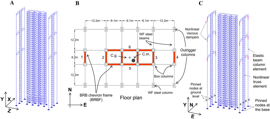
Figure 5. Prototype 40-story tall building equipped with a damped outriggers system: (A) Isometric view; (B) Floor plan; and (C) Analytical substructure for multi-directional RTHS (courtesy of Al-Subaihawi et al. (2024a)).
4.1.2 Natural hazards description
The earthquake RTHS utilizes the ground motion recorded at the Saratoga Aloha Avenue station during the 1989 Loma Prieta earthquake. This ground motion is scaled to the MCE hazard level, with the uniform hazard curve at the building’s location serving as the target response spectrum. The scaling minimizes the error between the geometric mean of the adjusted ground motion and the target response spectrum within the 0.5s–10s period range, using the following error weighting: 10
A 1/150 scaled aerodynamic model of the building is built and tested in the NHERI FIU Wall of Wind facility to measure the time history data of wind pressure during a simulated wind storm. The wind tunnel model has 336 pressure taps distributed around the model’s surfaces. The wind pressure at each floor level of the building is calculated by linear interpolation of the time history data between pressure taps. The wind storm has a design wind speed of 38 m/s at the equivalent full-scale wind intensity, derived from the 3-s gust wind speed specified in ASCE 7–10 (ASCE, 2010). The wind tunnel tests are conducted with a duration time of 325 s. Lateral wind loads in the east-west and north-south directions and torsional loading normal to the building’s floor plan are obtained by multiplying the wind pressure by the tributary areas.
4.1.3 Multi-directional RTHS description
The analytical substructure for the RTHS is developed using HyCoM-3D, and consists of a 3D finite element model of the building with nonlinear viscous dampers. The experimental substructure consists of one full-scale rate-dependent nonlinear viscous damper, with the remaining dampers modeled numerically with online model updating, as explained below. The analytical substructure consists of 1,080 nonlinear truss elements to model the buckling restrained braces and 40 geometric stiffness elements to model the lean-on columns. For the earthquake RTHS an eccentricity of the floor mass of 5% of the building’s floor plan dimensions is specified in both horizontal directions to induce torsional loading. To allow the equations of motion to be integrated in real time with an integration time step of 11/1,024 s, a super element is used to model all of the elastic elements of the structure, excluding the outrigger trusses and columns that developed inelastic response under the earthquake load. The use of the super element applied static condensation to the model, reducing the model’s number of degrees of freedom from 3,974 to 1,429.
Five nonlinear viscous dampers are placed between each outrigger truss and perimeter column for the earthquake RTHS and three nonlinear viscous dampers for the wind RTHS, leading to a total of 60 and 36 dampers for the earthquake and wind RTHS, respectively. The experimental substructure consisting of one full-scale nonlinear damper has a 600 kN load capacity and a 125 mm stroke. The remaining dampers are modeled analytically using an explicit formulated nonlinear Maxwell model developed by (Al-Subaihawi et al., 2022) and their parameters are updated in real time using an Unscented Kalman Filter.
The unconditionally stable parametrically dissipative MKR-
4.1.4 Results and outcomes
Figures 6A, B show the time history of the displacement and twist of the building roof under the two natural hazards. The twist under earthquake loading is induced by the 5% eccentricity described previously, while that under wind loading is due to the development of differential pressures that were measured around the perimeter of the building during the wind tunnel testing. The 3D RTHS results demonstrate the essential multi-axis behavior of the structure. For the RTHS earthquake, residual roof displacement and twist caused by the buckling restrained braces’ inelastic response are captured in both the North-South and East-West directions. Due to the combined translation and torsional motions of the building, inelastic deformations are observed in the buckling restrained braces over the height of the building. Figures 6C, D shows the ductility demand in the buckling restrained braces of four selected BRBFs over the height of the building in the North-South and East-West directions. Significant differences in the ductility demand of each BRBF are observed due to the torsional effects of building vibration. This outcome illustrates the importance of considering 3D models that include torsional degrees of freedom in order to capture the accurate inelastic response of a structure during a strong earthquake.
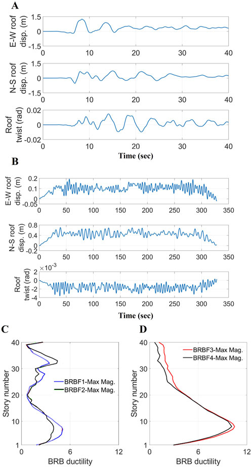
Figure 6. Roof displacement time histories: (A) Earthquake RTHS; and (B) Wind RTHS; Maximum magnitude of BRB ductility over the height of the building: (C) N-S direction; and (D) E-W direction (courtesy of Al-Subaihawi et al. (2024a)).
For the wind RTHS, while no roof residual displacement and twist are found, the building exhibits a static component of displacement and twist due to the combination of along-wind and cross-wind effects, as shown in Figure 6B. Consequently, this torsional effect can generate an acceleration increase at the corners of the building. Table 1 compares the peak resultant floor accelerations at the center and corner of the floor plan from selected floors. The acceleration of the corner on the
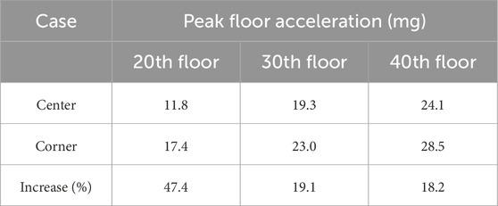
Table 1. Peak resultant floor acceleration at the center and corner of floor plan for wind RTHS.
The measured experimental damper response is compared with the numerical damper model response prediction using the updated model parameter values from the online model updating algorithm. The comparison indicates that the Normalized Root Mean Square Errors (NRMSE) for the earthquake and wind RTHS are 1.29% and 2.42%, respectively, indicating an excellent prediction by the online model updating method. It is also found that the force-deformation hysteric response of the viscous dampers possessed different characteristics under earthquake and wind events, with the wind-induced response exhibiting a static drift due to the static component of the along-wind effect. During the RTHS earthquakes, the dampers developed higher velocities and therefore forces compared to that of the wind RTHS; details can be found in (Al-Subaihawi et al., 2024a).
As noted above, the outcomes from the 3D RTHS illustrate the importance of using 3D models that include torsional degrees of freedom in order to capture the accurate inelastic response of a structure during a strong earthquake and floor accelerations during wind storms. The results from the study provide a practical framework for experimentally investigating the 3D performance of civil structures under multi-natural hazards.
Test results and data (Al Subaihawi et al., 2023a; Al Subaihawi et al., 2023b; Kolay et al., 2023) have been uploaded to the DesignSafe Data Depot Repository and can be downloaded at https://www.designsafe-ci.org/data/browser/public/designsafe.storage.published/PRJ-1439.
4.2 Multi-physics RTHS of a tall building with soil-foundation system using neural networks
To account for soil-structure effects, a piled reinforced concrete raft foundation is designed using a performance-based design approach for the 40-story building described in Section 4.1.1, and is used to perform RTHS. Figure 4B shows the RTHS framework used to model the soil-foundation system. The structure consists of a 2D version of the 40-story building described in Section 4.1, considering a planar model in the plane of the outrigger system in the NS direction. Two parallel nonlinear viscous dampers are placed between the ends of each outrigger truss and the adjacent outrigger column at the
4.2.1 Training and validation of NN model
The NN model for the soil-foundation system contains a block of four long-short-term memory (LSTM) layers in parallel with a rectified linear unit (ReLU). The LSTM block has four hidden layers, with each hidden layer having 75 neurons. To train the NN model, a 2D SFSI model is developed using OpenSees (Mazzoni, 2006). The OpenSees building model contains 717 DOFs and 388 elements while the soil-foundation system model consists of 2,478 DOFs and 2,996 elements. The viscous dampers are modeled using a Kelvin-Voigt model and the damping coefficient is obtained by linearizing the nonlinear viscous damper (Kolay and Ricles, 2018). To generate the training and validation data set, the Opensees model of the SFSI system is subjected to a set of wind load records. The wind loads are obtained by performing wind tunnel tests at the NHERI FIU Wall of Wind facility, where the experimental campaign consisted of 23 different basic wind speeds and 13 different wind directions. The training set for the NN model consists of 2093 records while the validation set consists of 299 records. Noise injection is used in the training set to avoid overfitting of the NN model. NVIDIA Quadro RTX 4000 Graphics Processing Units (GPUs) are used to speed up the training and validation process of the NN model.
The RTHS test matrix is given in Table 2. Test 1 is considered the baseline test, as it contains the largest number of training and validation records. Test 2 investigates the effect of the basic wind speed discretization in the training records. Test 3 stopped the NN model training at a larger value of the target root mean square error (RMSE) during the training process compared to Test 2. Tests 4 and 5 examine the effectiveness of noise injection and the ReLU, respectively, by omitting these effects in the training of the NN model. Test 6 adds a higher amount of noise injection during the training of the NN model. Test 7 is an RTHS where the structure is supported by a rigid base foundation (i.e., no soil-foundation system is included in the RTHS).

Table 2. Multi-physics RTHS test matrix.
4.2.2 Results and outcomes
To assess the accuracy of the NN model, the multi-physics RTHS results of soil-foundation displacement are compared with numerical simulation results from an OpenSees model of only the soil-foundation system. The restoring forces at the interface between the building and foundation from the multi-physics RTHS are used as the inputs for the OpenSees model and the resulting displacements at the ground level are compared to each other. Figure 7 compares the time history of the interface horizontal displacements at the ground level obtained from the OpenSees and the multi-physics RTHS. Tests 4 and 5 are not included since they contain a large level of noise without noise injection training (Test 4) and instability without the ReLU (Test 5). The comparisons show that the NN model can produce a better prediction of soil-foundation-structure interaction effects when trained to a smaller target RMSE value and using a larger number of training sets. Overall, the NN model can precisely predict the dynamics of the nonlinear soil-foundation system and is suitable for performing multi-physics RTHS.
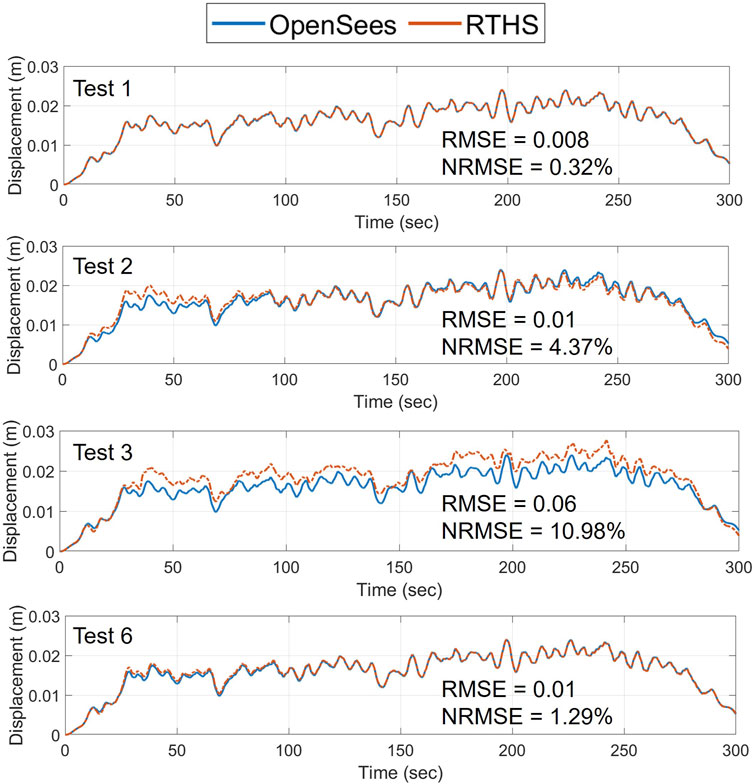
Figure 7. Comparison of multi-physics RTHS and OpenSees numerical simulation results of interface horizontal displacements at the ground level (courtesy of Al-Subaihawi et al. (2024)).
After evaluating the NN model, the multi-physics RTHS results are compared with the RTHS test without SFSI effects (Test 7), as well as with a numerical simulation of the complete system using the OpenSees model. The time histories of roof displacements are shown plotted in Figure 8. The OpenSees numerical simulation results in Figure 8 are labeled Reference. The multi-physics RTHS tests with SFSI effects have overall similar results compared with the reference solution, where Test 1 produces the smallest error. The effects of SFSI caused the maximum roof displacement of Test 1 to increase by 60% compared to Test 7 (rigid foundation). The time histories of the experimental damper deformations are also examined (not shown due to lack of space). The damper accumulated 0.04 m of deformation under the applied gravity loading at the beginning of the RTHS of Test 1, while the damper deformed only 0.01 m under gravity loading when the SFSI effects are excluded (Test 7). During the imposed wind loading of the RTHS the maximum damper deformation demand increased up to 90% when considering SFSI effects.
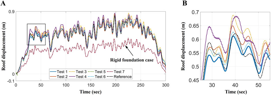
Figure 8. Time histories of roof displacements: (A) Complete time history; and (B) Zoom view (courtesy of Al-Subaihawi et al. (2024)).
The results of this study validate the proposed multi-physics RTHS framework. Furthermore, the effects of soil-structure interaction are shown to increase the deformation demand on the dampers as well as lateral displacements of the building during a wind storm. By taking into account the effects of soil-foundation-structure interaction, a more realistic structural wind design methodology can be developed, enabling the evaluation of more effective mitigation strategies to be accomplished.
Test results and data (Al Subaihawi et al., 2023a; Al Subaihawi et al., 2023b; Kolay et al., 2023) have been uploaded to the DesignSafe Data Depot Repository and can be downloaded at https://www.designsafe-ci.org/data/browser/public/designsafe.storage.published/PRJ-1439.
4.3 3D RTHS multi-axis shake table tests of floor isolation systems for mitigating seismic effects on mission-critical building contents
Earthquakes can heavily damage critical building contents and nonstructural equipment, resulting in a significant economic loss. Floor isolation systems (FIS) are a promising retrofitting approach to protect such vital building contents. These systems must be designed and maintained to adequately resist the effects of service and extreme vibrational loads on the building. A new type of rolling pendulum (RP) based FIS has been studied at the NHERI Lehigh EF using the new real-time cyber-physical structural systems multi-directional shake table (Villalobos Vega et al., 2022; Villalobos Vega et al., 2024). The prototype RP-based FIS is a single full-scale OCTO-
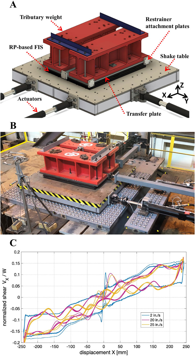
Figure 9. (A) Schematic of the RP-based FIS; (B) Photograph of the dynamic test setup; (C) Normalized shear-displacement of the RP-based FIS response under uni-directional harmonic displacements with maximum speeds of 2 in/s, 20 in/s and 25 in/s (courtesy of Villalobos Vega et al. (2024)).
4.3.1 Characterization tests
Characterization tests are performed under prescribed displacements to investigate the FIS response when subjected to a variety of multi-directional conditions. Figure 9C plots the normalized shear force and displacement response of the RP-based FIS subjected to uni-directional harmonic displacement inputs with three different maximum speeds of 2 in/s, 20 in/s, and 25 in/s. The normalized shear force is calculated by dividing the measured restoring force from the load cell by the equipment weight on top of the FIS. Results show that higher frequency inputs have a predominant effect on the FIS dynamic response. This can be attributed to higher vertical inertial effects resulting from higher velocities.
4.3.2 3D RTHS multi-axis shake table tests
To evaluate the seismic performance of the RP-based FIS and associated building-FIS interaction, a 3-story steel moment resisting frame (SMRF) building designed for the SAC project (Ohtori et al., 2004) is used for performing RTHS multi-axis shake table tests. The RP-based FIS is assumed to be located on the second floor of the building and a tributary weight of 17.9 kN of the dead load of the server cabinet is installed on top of the FIS. Figure 10 presents the multi-axis RTHS framework used to perform the simulations. The analytical substructure consists of a 3D finite element model of the 3-story SMRF building and a server cabinet. All the beams and columns in the MRFs are modeled using 3D inelastic explicit force-based fiber elements, and the remaining components that include the server cabinet and building gravity system’s beams are modeled using 3D elastic elements. An eccentric floor mass and P-
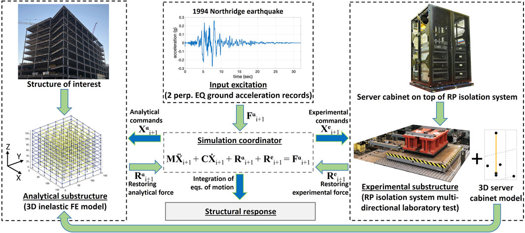
Figure 10. Famework for conducting 3D RTHS multi-axis shake table test of structures equipped with RP-based FIS subjected to multi-directional earthquake ground motions (courtesy of Villalobos Vega et al. (2024)).
4.3.3 Results and outcomes
The absolute (i.e., total) bi-directional accelerations of the second floor of the SMRF are analyzed. It is found that a 68%–82% reduction in equipment acceleration is achieved by isolating the equipment compared to when the equipment is not isolated. The results show that the FIS can effectively isolate sensitive mission-critical equipment under multi-directional ground motions. The 3D RTHS multi-axis shake table test successfully validates the seismic protection performance of 3D RP-based FIS on nonstructural components. The multi-axis motions that include twist acceleration caused by the eccentric mass of the building are found to be important, for they increase the absolute accelerations at locations where the FIS are attached to the floor of the building. Therefore, it is important to account for multi-axis accelerations as done in the study. The results of this study provide a rigorous methodology for assessing the multi-directional seismic performance of FIS’s in mission critical buildings that house sensitive equipment.
Test results and data (Harvey et al., 2022) have been uploaded to the DesignSafe Data Depot Repository and can be downloaded at https://www.designsafe-ci.org/data/browser/public/designsafe.storage.published/PRJ-3649.
4.4 Multi-directional cyclic lateral loading tests of self-centering cross-laminated timber shear wall sub-assembly
There has been a growing interest in the use of cross-laminated timber (CLT) for the construction of new building systems. The material is a renewable resource with a reduced carbon footprint compared to conventional construction. CLT panels are constructed to create structural elements, where the layers of the timber boards are laminated in an orthogonal pattern and glued together on their wide face. Post-tensioned self-centering CLT structural walls (SC-CLT walls) have been developed where CLT panels are erected vertically and post-tensioning is added. This type of structural element has been recently studied by (Ganey et al., 2017; Pei et al., 2019), where the results demonstrated the potential of the SC-CLT wall to reduce seismic-induced damage in CLT buildings. These prior studies are however limited in scope, where the test specimens are subjected to only unidirectional displacements in the plane of the wall, and neglected the effect of bi-directional earthquake ground motions on the performance of the wall. To study the effect of bi-directional loading on the response of SC-CLT walls, a 0.625-scale subassembly system consisting of a CLT-floor diaphragm-gravity system with an SC-CLT coupled shear wall and collector beams is constructed at the NHERI Lehigh EF and used to perform multi-directional load testing.
4.4.1 SC-CLT wall test setup
Figure 11 shows the 0.625-scale timber test subassembly. The SC-CLT wall is composed of two post-tensioned 5-layer CLT wall panels that are connected with U-shaped flexural plates (UFPs) for energy dissipation. Each CLT wall panel is equipped with a 32 mm-diameter post-pensioned (PT) steel bar. Two glulam collector beams are connected to the SC-CLT wall, one on each side of the wall, to collect and transfer the in-plane (in the direction of the SC-CLT wall) lateral forces from the CLT floor diaphragm through a slotted connection and deliver them to the SC-CLT wall. The out-of-plane bearings are designed to transfer the out-of-plane load from the CLT floor diaphragm to the SC-CLT wall and brace the wall in the out-of-plane direction. Shear keys are placed at the base of each wall to prevent sliding of the wall and to transfer the wall base shear to the foundation. The gravity load system consists of glulam gravity beams and columns with pinned bases. The beam-to-column connections of the gravity load system are designed to accommodate the multi-directional lateral drift of the test sub-assembly. The test fixtures include two actuators placed in-plane to the walls to displace the test sub-assembly through the floor diaphragm. Two out-of-plane actuators are connected to the CLT floor diaphragm to subject the sub-assembly to out-of-plane displacements. Multi-directional displacements of the test sub-assembly are controlled at a structure-physical-node, denoted SPN, which is located in the middle of the SC-CLT wall at the top of the floor diaphragm. All degrees of freedom of the test sub-assembly are associated with the SPN. Continuous real-time feedback from two sets of displacement sensors, attached to the CLT floor diaphragm, are used to measure the displaced position of two measurement-structure nodes (MSN) at the north and south ends of the wall and incorporated into a multidirectional kinematic compensation algorithm (Mercan et al., 2009) to achieve precise actuator control and the target displacements of the SPN.

Figure 11. Multi-directional test setup of cross-laminated timber self-centering coupled walls-floor diaphragm-gravity system (courtesy of Amer et al. (2024)).
4.4.2 Multi-directional cyclic lateral loading protocol
The experimental campaign consists of applying predefined unidirectional and multi-directional quasi-static displacement histories to the subassembly, imposing the floor diaphragm to reach a predefined target floor diaphragm story drift, denoted
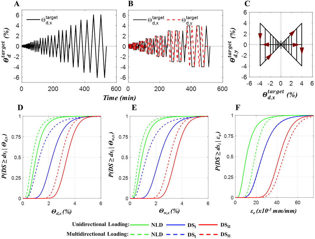
Figure 12. Cyclic lateral loading protocol: (A) Time history of imposed in-plane floor diaphragm drift under unidirectional test; (B) Time history of imposed in-plane and out-of-plane floor diaphragm drift under multi-directional test: and (C) Associated multi-directional bow-tie-shaped loading trajectory; Wall component fragility functions conditioned on (D) In-plane floor diaphragm story drift
4.4.3 Results and outcomes
To evaluate lateral response of the SC-CLT wall, four damage states are defined that included: (1) Normal Loading Defect (NLD), which involves minor or cosmetic damage to the CLT wall panel, such as fine compression splits or wrinkling, with no need for repairs; (2) Damage State
The in-plane lateral load response of the SC-CLT wall between uni-directional and multi-directional tests are evaluated by (Amer et al., 2024) where the results show that the multi-directional loading generates earlier damage to the SC-CLT wall panel. Figures 12D–F compare the fragility functions of the wall components for the in-plane tests, where the engineering demand parameters (EDP) are
Test results and data (Amer et al., 2023) have been uploaded to the DesignSafe Data Depot Repository and can be downloaded at https://www.designsafe-ci.org/data/browser/public/designsafe.storage.published/PRJ-3850.
4.5 Mixed-mode cyclic loading tests of seismic collector connections for steel-frame buildings
Seismic collectors are critical elements of the seismic force-resisting system that transmit the inertial forces that develop in building floor systems to the primary vertical-plane elements of the seismic force-resisting system. In steel-frame buildings in the U.S., seismic collectors are elements of the floor system specially-designed to carry tension and compression axial forces. Often a line of gravity-load-carrying beams and connections within the floor system are enhanced to serve as a collector. These beams are then designed as beam-columns, and the connections between these beams and the intervening columns in the load path are designed for tension and compression axial forces. Little past research has focused on steel collectors, and the seismic response of these elements is not well established in the literature. The research project scope includes: (1) nonlinear analysis of steel seismic collectors in steel buildings; (2) large-scale testing of steel seismic collector connections at the NHERI Lehigh EF; and (3) shake table testing of a two-story steel-frame structure at the NHERI Earthquake Shake Table Experimental Facility at the University of California, San Diego (Pandey et al., 2022).
4.5.1 Description of steel seismic collector connection loading conditions
The connections within a steel seismic collector, between the collector beams and the columns within the collector force path, may be subjected to tension or compression axial forces, with the largest magnitude forces in the connections closest to the primary vertical-plane element of the seismic force-resisting system (e.g., braced frame). Collector connection types include bolted shear tabs, top-flange-welded (TFW) connections, and all-flange-welded (AFW) connections. Currently, collector connections are designed for the collector axial force and shear from gravity loads, not additional demands due to building lateral drift.
4.5.2 Steel seismic collector connection loading test setup
As shown in Figure 13A, the steel seismic collector connection test setup at the NHERI Lehigh EF includes a test specimen with a single collector connection and the associated collector beam and column (shown in red). The test setup separates the collector beam into two parts, where one part is included in a re-usable test fixture (shown in gray) and the other part is part of the test specimen (shown in red). The reusable test fixture also includes a second column, and together the reusable test fixture and test specimen model two columns and one collector beam in the collector force path. The columns and beams are lying in a horizontal plane to facilitate lateral bracing from the laboratory’s strong floor. The bases of the columns provide supports, namely, a roller support at the base of the column in the reusable test fixture (shown in gray) and a pinned support at the base of the column of the test specimen (shown in red). These supports enable the columns to develop axial forces as reactions to shear forces that develop in the collector beam.

Figure 13. (A) Schematic of collector connection test setup; (B) Photograph of collector connection; (C) Loading protocol with simultaneously applied force and imposed rotation (1 kip = 4.45 kN).
As shown in Figure 13B, the unique feature of the steel seismic collector connection test setup is the capability to simultaneously apply a large axial force (up to 4,800 kN) using the loading actuators (painted black, on the left) and impose a rotation of the test specimen column (to simulate the rotation of a column within the collector force path to accommodate the building lateral drift) using the rotation actuators (painted blue on the right), which also provide the main reaction to the applied axial force.
Three loading protocols have been developed for steel seismic collector connection tests: (1) constant column rotation (including the possibility of zero rotation) with applied cyclic axial forces; (2) constant column rotation with applied cyclic axial connection deformations; and (3) simultaneously varying column rotation and axial force to simulate seismic demand histories on collector connections obtained from nonlinear analysis of collectors in a steel-frame building under earthquake loading. Note that test protocol (1), with constant rotation and applied cyclic axial forces, is useful to characterize the initial stiffness and strength of a steel seismic collector connection, and the complete loading history of the test usually involves a series of stages with each stage having a given constant rotation. Test protocol (2), with constant rotation and applied cyclic axial connection deformations, is useful for testing the connection to failure.
4.5.3 Results and outcomes
Three top-flange-welded (TFW) connections and two all-flange-welded (AFW) connections have been tested. The TFW connection specimens are 0.75 scale and the AFW connection specimens are 0.67 scale. For the TFW specimens, the largest applied force exceeded 4,400 kN. Generally, the TFW connections performed as expected, reaching the expected force capacity. The tests have shown that the imposed column rotation (to simulate the effects of the building lateral drift) can reduce the force capacity.
Figure 13C shows the results from using test protocol (3), simultaneously varying column rotation and axial force to simulate seismic demand histories, in the third TFW specimen test, showing that the loading protocol follows the target imposed rotations and axial forces to fully simulate the seismic demand histories on a steel seismic collector connection.
When complete, the test results will substantially increase the knowledge-base on the seismic response of steel seismic collectors, and recommendations for practical design and fabrication will be made. Project partners include seismic structural engineers, structural steel fabricators, and regulatory organizations.
Upon completion of this study, the results will be uploaded and archived in the DesignSafe Data Depot Repository.
5 Summary and conclusions
The Natural Hazards Engineering Research Infrastructure (NHERI) Lehigh Experimental Facility (EF) is an open-access state-of-art experimental and computational research facility. The unique resources and capabilities of the facility enable novel and impactful natural hazards research to be performed. The unique capabilities include the ability to conduct 3D large-scale multi-directional Real-Time Hybrid Simulation (RTHS) that combine physical experiments with computer-based simulations for evaluating the performance of large-scale components and systems. Several testing protocols are enabled at the facility, including: (1) large-scale HS; (2) large-scale RTHS; (3) large-scale RTHS with real-time online model updating; (4) large-scale RTHS with multiple experimental substructures; (5) geographically distributed HS; (6) geographically distributed real-time hybrid earthquake simulation; (7) quasi-static testing; (8) dynamic testing; (9) multi-directional RTHS multi-axis shake table tests; and (10) multi-physics RTHS. These testing protocols are supported by the facility’s unique portfolio of experimental equipment, instrumentation, testbeds, and testing protocols, in addition to the newly developed NHERI Lehigh Real-time Cyber-Physical Structural Systems Testing Laboratory and Real-time Cyber-Physical Structural Systems Multi-directional Shake Table. The NHERI Lehigh EF will continue to enhance its testing capabilities to address a wider range of natural hazards and infrastructure challenges. Planned expansions include a large wave flume for examining fluid-structure interactions in coastal infrastructure and a large-scale soil box for studying soil-structure interactions in onshore and coastal systems exposed to multiple natural hazards.
Several selected example research projects recently performed at the NHERI Lehigh EF are presented. These projects include: (1) development of a framework for multi-directional RTHS of a tall building equipped with nonlinear viscous dampers to enable 3D performance evaluation of the system when subjected to earthquake and wind natural hazards; (2) multi-physics RTHS of a tall building with a soil-foundation system modeled using neural networks to assess the effects on the efficacy of the response modification devices and performance of the structure subjected to wind natural hazards; (3) 3D RTHS multi-axis shake table tests of floor isolation systems to evaluate their effectiveness to mitigate seismic-induced vibrations and damage of critical building contents; (4) multi-directional cyclic lateral loading tests of a self-centering cross-laminated timber shear wall sub-assembly to examine the effects of bi-directional loading on the seismic resiliency of these components in mass timber constructed buildings; and, (5) large-scale tests of seismic collectors in a steel frame floor system to evaluate the performance, and enhance our knowledge of the seismic behavior and design of collector’s connections to the lateral force resisting system.
Multi-directional RTHS results on a tall building underscore the importance of 3D models in accurately capturing inelastic responses to natural hazards. Similarly, multi-physics RTHS findings reveal the significant influence of soil-structure interaction on deformation demands in outrigger system dampers. These studies demonstrate that structural responses to natural hazards can vary considerably when multi-directional and multi-physics effects are taken into account.
The successful 3D RTHS multi-axis shake table test validates the seismic protection effectiveness of 3D floor isolation systems for critical equipment, particularly by considering in-plane angular floor accelerations. Experimental results from SC-CLT shear wall tests show that multi-directional loading exacerbates damage, emphasizing the necessity of incorporating such effects into the performance-based design of mass timber systems. Additionally, large-scale seismic collector tests provide key insights into seismic behavior, notably the axial forces induced during inter-story drift and the effects of rotational deformations at the collector-to-lateral force-resisting system connection.
Collectively, these projects highlight the critical role of large-scale 3D testing in enhancing our understanding of structural and non-structural component performance under natural hazards. By utilizing the NHERI Lehigh EF’s advanced testing capabilities, researchers can drive innovation in natural hazards engineering through cutting-edge, high-impact studies.
Additional information about the NHERI Lehigh EF can be found at the facility’s website at https://lehigh.designsafe-ci.org/facility/overview/. This information includes an overview of the facility, along with the portfolio of equipment and resources, experimental protocols, portfolio of research projects, the facility’s education and outreach program, and contact information.
Data availability statement
The original contributions presented in the study are included in the article, further inquiries can be directed to the corresponding authors.
Author contributions
LC: Conceptualization, Data curation, Formal Analysis, Investigation, Methodology, Validation, Writing–original draft, Writing–review and editing. TM: Conceptualization, Data curation, Formal Analysis, Investigation, Software, Validation, Writing–original draft, Writing–review and editing. JR: Conceptualization, Funding acquisition, Investigation, Methodology, Project administration, Supervision, Writing–original draft, Writing–review and editing. RS: Conceptualization, Funding acquisition, Investigation, Methodology, Project administration, Supervision, Writing–original draft, Writing–review and editing. CR: Conceptualization, Funding acquisition, Investigation, Methodology, Project administration, Supervision, Writing–original draft, Writing–review and editing. JS: Funding acquisition, Project administration, Resources, Supervision, Writing–original draft, Writing–review and editing.
Funding
The author(s) declare that financial support was received for the research and/or publication of this article. The research reported in this paper was supported by several grants from the National Science Foundation. This included Award No. CMMI-1663376 Analysis and Design of a Nonholonomic, Impact-Based, Dual-Mode Vibration Isolator/Absorber System, Award No. OIA-1929151 RII Track-4: Quantifying Seismic Resilience of Multi-Functional Floor Isolation Systems through Cyber-Physical Testing, Award No. CMMI-1943917 CAREER: Mitigation of Seismic Risk to Critical Building Contents via Optimum Nonlinear 3D Isolation, Award No. CMMI-1463497 Collaborative Research: Semi-Active Controlled Cladding Panels for Multi-Hazard Resilient Buildings, Award No. CMMI-1635227 Collaborative Research: A Resilience-based Seismic Design Methodology for Tall Wood Buildings, and Award No. CMMI-1662816 Advancing Knowledge on the Performance of Seismic Collectors in Steel Building Structures. The research reported in this paper was performed at the NHERI Lehigh Large-Scale Multi-Directional Hybrid Simulation Experimental Facility. Financial support for the operation of the NHERI Lehigh Large-Scale Multi-Directional Hybrid Simulation Experimental Facility was provided by the National Science Foundation under Cooperative Agreement No. CMMI-1520765 and No. CMMI-2037771.
Acknowledgments
The authors are grateful for the financial support of the National Science Foundation and that provided by the Pennsylvania Infrastructure Technology Alliance and Lehigh University.
Conflict of interest
The authors declare that the research was conducted in the absence of any commercial or financial relationships that could be construed as a potential conflict of interest.
Generative AI statement
The author(s) declare that no Generative AI was used in the creation of this manuscript.
Publisher’s note
All claims expressed in this article are solely those of the authors and do not necessarily represent those of their affiliated organizations, or those of the publisher, the editors and the reviewers. Any product that may be evaluated in this article, or claim that may be made by its manufacturer, is not guaranteed or endorsed by the publisher.
Author disclaimer
Any opinions, findings, and conclusions expressed in this paper are those of the authors and do not necessarily reflect the views of the National Science Foundation or others acknowledged herein.
References
Al Subaihawi, S., Kolay, C., Marullo, T., Ricles, J., and Quiel, S. (2023a). Assessment of wind-induced vibration mitigation in a tall building with damped outriggers using real-time hybrid simulations. Designsafe-CI. doi:10.17603/ds2-mj64-6s83
Al-Subaihawi, S., Kolay, C., Marullo, T., Ricles, J. M., and Quiel, S. E. (2020). Assessment of wind-induced vibration mitigation in a tall building with damped outriggers using real-time hybrid simulations. Eng. Struct. 205, 110044. doi:10.1016/j.engstruct.2019.110044
Al Subaihawi, S., Ricles, J., Quiel, S., and Marullo, T. (2023b). Online explicit model updating of nonlinear viscous dampers for real time hybrid simulation. Designsafe-CI. doi:10.17603/ds2-pnr0-7476
Al-Subaihawi, S., Ricles, J., Quiel, S., and Marullo, T. (2024a). Development of multi-directional real-time hybrid simulation for tall buildings subject to multi-natural hazards. Eng. Struct. 315, 118348. doi:10.1016/j.engstruct.2024.118348
Al-Subaihawi, S., Ricles, J., Quiel, S., Marullo, T., and Malik, F. (2024). Real-time hybrid simulation of structural systems with soil-foundation interaction effects using neural networks. Earthq. Eng. Struct. Dyn. 53, 4688–4718. doi:10.1002/eqe.4236
Al-Subaihawi, S., Ricles, J. M., and Quiel, S. E. (2022). Online explicit model updating of nonlinear viscous dampers for real time hybrid simulation. Soil Dyn. Earthq. Eng. 154, 107108. doi:10.1016/j.soildyn.2021.107108
Al-Subaihawi, S., Ricles, J. M., Quiel, S. E., and Marullo, T. (2024b). Unconditionally stable central difference dissipative algorithm for multi-directional real-time hybrid simulations of large nonlinear structural systems. J. Earthq. Eng. 28, 3256–3290. doi:10.1080/13632469.2024.2333822
Amer, A., Marullo, T., Sause, R., and Ricles, J. (2023). Data for unidirectional and multi-directional cyclic lateral-load testing of self-centering cross-laminated timber shear wall-floor diaphragm sub-assembly. Designsafe-CI. doi:10.17603/DS2-DDV9-2235
Amer, A., Sause, R., and Ricles, J. (2024). Experimental response and damage of sc-clt shear walls under multidirectional cyclic lateral loading. J. Struct. Eng. 150. doi:10.1061/jsendh.steng-12576
ASCE (2010). Minimum design loads for buildings and other structures,american socitey of civil engineering. (Reston, VA: ASCE/SEI 7-10 edition).
Azzi, Z., Matus, M., Elawady, A., Zisis, I., Irwin, P., and Gan Chowdhury, A. (2020). Aeroelastic testing of span-wire traffic signal systems. Front. Built Environ. 6. doi:10.3389/fbuil.2020.00111
Cao, L., Malik, F., Al-Subhaihawi, S., Miao, W., Ricles, J., Marullo, T., et al. (2024). “Real time hybrid simulation (rths) of a 2-story building equipped with novel base isolation systems,” in World Conference on earthquake Engineering proceedings (WCEE2024), USA, JULY 5, 2024.
Cao, L., Marullo, T., Al-Subaihawi, S., Kolay, C., Amer, A., Ricles, J., et al. (2020). Nheri lehigh experimental facility with large-scale multi-directional hybrid simulation testing capabilities. Front. Built Environ. 6. doi:10.3389/fbuil.2020.00107
Catarelli, R. A., Fernández-Cabán, P. L., Phillips, B. M., Bridge, J. A., Masters, F. J., Gurley, K. R., et al. (2020). Automation and new capabilities in the university of Florida nheri boundary layer wind tunnel. Front. Built Environ. 6. doi:10.3389/fbuil.2020.558151
Chae, Y., Kazemibidokhti, K., and Ricles, J. M. (2013a). Adaptive time series compensator for delay compensation of servo-hydraulic actuator systems for real-time hybrid simulation. Earthq. Eng. and Struct. Dyn. 42, 1697–1715. doi:10.1002/eqe.2294
Chae, Y., Ricles, J. M., and Sause, R. (2013b). Modeling of a large-scale Magneto-Rheological damper for seismic hazard mitigation. Part I: passive mode. Earthq. Eng. and Struct. Dyn. 42, 669–685. doi:10.1002/eqe.2237
Chae, Y., Ricles, J. M., and Sause, R. (2014). Large-scale real-time hybrid simulation of a three-story steel frame building with Magneto-Rheological dampers. Earthq. Eng. and Struct. Dyn. 43, 1915–1933. doi:10.1002/eqe.2429
Chen, C., and Ricles, J. M. (2008). Development of direct integration algorithms for structural dynamics using discrete control theory. J. Eng. Mech. 134, 676–683. doi:10.1061/(asce)0733-9399(2008)134:8(676)
Chen, C., and Ricles, J. M. (2012). Large-scale real-time hybrid simulation involving multiple experimental substructures and adaptive actuator delay compensation. Earthq. Eng. and Struct. Dyn. 41, 549–569. doi:10.1002/eqe.1144
Chen, C., Ricles, J. M., Marullo, T. M., and Mercan, O. (2009). Real-time hybrid testing using the unconditionally stable explicit CR integration algorithm. Earthq. Eng. and Struct. Dyn. 38, 23–44. doi:10.1002/eqe.838
Coble, D., Cao, L., Downey, A. R., and Ricles, J. M. (2024). Physics-informed machine learning for dry friction and backlash modeling in structural control systems. Mech. Syst. Signal Process. 218, 111522. doi:10.1016/j.ymssp.2024.111522
Dong, B., Sause, R., and Ricles, J. (2018a). “Seismic performance of steel MRF structures with nonlinear viscous dampers from real-time hybrid simulations,” in Proceedings of the 9th international conference on behavior of steel structures in seismic areas (Christchurch, New Zealand: STESSA).
Dong, B., Sause, R., and Ricles, J. M. (2015). Accurate real-time hybrid earthquake simulations on large-scale mdof steel structure with nonlinear viscous dampers. Earthq. Eng. and Struct. Dyn. 44, 2035–2055. doi:10.1002/eqe.2572
Dong, B., Sause, R., and Ricles, J. M. (2018b). Seismic response and damage of reduced-strength steel MRF structures with nonlinear viscous dampers. J. Struct. Eng. 144, 04018221. doi:10.1061/(asce)st.1943-541x.0002226
Downey, A., Cao, L., Laflamme, S., Taylor, D., and Ricles, J. (2016). High capacity variable friction damper based on band brake technology. Eng. Struct. 113, 287–298. doi:10.1016/j.engstruct.2016.01.035
Ganey, R., Berman, J., Akbas, T., Loftus, S., Daniel Dolan, J., Sause, R., et al. (2017). Experimental investigation of self-centering cross-laminated timber walls. J. Struct. Eng. 143. doi:10.1061/(asce)st.1943-541x.0001877
Harvey, P., Covarrubias Vargas, B. A., Cao, L., and Ricles, J. (2022). Characterization tests of rolling pendulum isolation bearings with different surface treatments. Designsafe-CI. doi:10.17603/DS2-5JE0-5F35
Karavasilis, T. L., Ricles, J. M., Sause, R., and Chen, C. (2011). Experimental evaluation of the seismic performance of steel mrfs with compressed elastomer dampers using large-scale real-time hybrid simulation. Eng. Struct. 33, 1859–1869. doi:10.1016/j.engstruct.2011.01.032
Kim, S. J., Christenson, R., Phillips, B., and Spencer, B. (2012). Geographically distributed real-time hybrid simulation of MR dampers for seismic hazard mitigation. Proc. 20th Analysis Comput. Specialty Conf., 382–393. doi:10.1061/9780784412374.034
Kolay, C., Al-Subaihawi, S., Marullo, T., Ricles, J., and Quiel, S. (2020). Multi-hazard real-time hybrid simulation of a tall building with damped outriggers. Int. J. Lifecycle Perform. Eng. 4 (1/2/3), 103–132. doi:10.1504/ijlcpe.2020.108937
Kolay, C., Al Subaihawi, S., Marullo, T., Ricles, J., and Quiel, S. (2023). Multi-hazard real-time hybrid simulation of a tall building with damped outriggers. Designsafe-CI. doi:10.17603/ds2-pq8k-vq38
Kolay, C., and Ricles, J. M. (2014). Development of a family of unconditionally stable explicit direct integration algorithms with controllable numerical energy dissipation. Earthq. Eng. and Struct. Dyn. 43, 1361–1380. doi:10.1002/eqe.2401
Kolay, C., and Ricles, J. M. (2018). Force-based frame element implementation for real-time hybrid simulation using explicit direct integration algorithms. J. Struct. Eng. 144. doi:10.1061/(asce)st.1943-541x.0001944
Kolay, C., and Ricles, J. M. (2019). Improved explicit integration algorithms for structural dynamic analysis with unconditional stability and controllable numerical dissipation. J. Earthq. Eng. 23, 771–792. doi:10.1080/13632469.2017.1326423
Kolay, C., Ricles, J. M., Marullo, T. M., Mahvashmohammadi, A., and Sause, R. (2015). Implementation and application of the unconditionally stable explicit parametrically dissipative KR-α method for real-time hybrid simulation. Earthq. Eng. and Struct. Dyn. 44, 735–755. doi:10.1002/eqe.2484
Lin, Y.-C., Sause, R., and Ricles, J. M. (2013). Seismic performance of steel self-centering, moment-resisting frame: hybrid simulations under design basis earthquake. J. Struct. Eng. 139, 1823–1832. doi:10.1061/(asce)st.1943-541x.0000745
Lomonaco, P., Cox, D., Higgins, C., Maddux, T., Bosma, B., Miller, R., et al. (2020). Building resilient coastal communities: the nheri experimental facility for surge, wave, and tsunami hazards. Front. Built Environ. 6. doi:10.3389/fbuil.2020.579729
Malik, F. N., Gorini, D. N., Ricles, J. M., and Rahnemoonfar, M. (2025). Multi-physics framework for seismic real-time hybrid simulation of soil-foundation-structural systems. Eng. Struct. under Rev.
Mazzoni, S. (2006). Opensees command language manual. Pacific Earthquake Engineering Research (PEER) Center.
Mercan, O., Ricles, J. M., Sause, R., and Marullo, T. (2009). Kinematic transformations for planar multi-directional pseudodynamic testing. Earthq. Eng. and Struct. Dyn. 38, 1093–1119. doi:10.1002/eqe.886
Moehle, J., Bozorgnia, Y., Jayaram, N., Jones, P., Rahnama, M., Shome, N., et al. (2011). “Case studies of the seismic performance of tall buildings designed by alternative means,” in Report 2011/05, pacific earthquake engineering research center (Berkeley, California: University of California).
Ohtori, Y., Christenson, R. E., Spencer, B. F., and Dyke, S. J. (2004). Benchmark control problems for seismically excited nonlinear buildings. J. Eng. Mech. 130, 366–385. doi:10.1061/(asce)0733-9399(2004)130:4(366)
Pandey, S., Fleischman, R., Sause, R., Ricles, J., and Uang, C.-M. (2022). Behavior of seismic collectors in steel building structures: Proceedings of the 12th National Conference in Earthquake Engineering. Salt Lake City, Utah, USA, June 27-July 1.
Pei, S., van de Lindt, J. W., Barbosa, A. R., Berman, J. W., McDonnell, E., Daniel Dolan, J., et al. (2019). Experimental seismic response of a resilient 2-story mass-timber building with post-tensioned rocking walls. J. Struct. Eng. 145. doi:10.1061/(asce)st.1943-541x.0002382
Perez, F. J., Pessiki, S., and Sause, R. (2013). Experimental lateral load response of unbonded post-tensioned precast concrete walls. ACI Struct. J. 110. doi:10.14359/51686159
Rathje, E. M., Dawson, C., Padgett, J. E., Pinelli, J.-P., Stanzione, D., Adair, A., et al. (2017). Designsafe: new cyberinfrastructure for natural hazards engineering. Nat. Hazards Rev. 18. doi:10.1061/(asce)nh.1527-6996.0000246
Ricles, J., Kolay, C., and Marullo, T. (2020). HyCoM-3D: a program for multi-hazard nonlinear dynamic analysis and real-time hybrid simulation of 3-D civil infrastructural systems. Bethlehem, PA: ATLSS Report No. 20-02, Lehigh Unversity.
Ricles, J., Marullo, T., and Roy, S. (2007). Multiple NEES equipment site soil-structure-foundation distributed hybrid simulations. Bethlehem, PA: Lehigh Unviersity. ATLSS Report No. 07-12.
Ricles, J. M., Fisher, J., Lu, L.-W., and Kaufmann, E. (2002a). Development of improved welded moment connections for earthquake-resistant design. J. Constr. Steel Res. 58, 565–604. doi:10.1016/s0143-974x(01)00095-5
Ricles, J. M., Mao, C., Lu, L.-W., and Fisher, J. W. (2002b). Inelastic cyclic testing of welded unreinforced moment connections. J. Struct. Eng. 128, 429–440. doi:10.1061/(asce)0733-9445(2002)128:4(429)
Villalobos Vega, E., Harvey, S., Ricles, J., Cao, L., and Burgos, D. T. (2022). “Multi-directional real-time hybrid simulation study of rolling pendulum isolation systems for seismic risk mitigation of critical building contents,” in Proceedings of the 12th National Conference in Earthquake Engineering, Salt Lake City, Utah, USA, June 27-July 1.
Villalobos Vega, E., Vanderheiden, E., and Harvey, P. (2024). “The performance of a rolling pendulum isolation system subject to 3d seismic excitation,” in Proceedings world conference on earthquake engineering (international association for earthquake engineering), USA, August 2-1998.
Keywords: large-scale experiments, real-time hybrid simulation, multi-directional, cyber-physical, multi-physics, multi-hazard
Citation: Cao L, Marullo TM, Ricles JM, Sause R, Reis C and Saunders J (2025) Recent developments and discoveries in natural hazards mitigation research at the NHERI Lehigh Experimental Facility. Front. Built Environ. 11:1567729. doi: 10.3389/fbuil.2025.1567729
Received: 28 January 2025; Accepted: 26 February 2025;
Published: 19 March 2025.
Edited by:
Cheryl Ann Blain, Naval Research Laboratory, United StatesReviewed by:
Pedro L. Fernández-Cabán, Florida A&M University - Florida State University College of Engineering, United StatesSimona Bianchi, Delft University of Technology, Netherlands
Copyright © 2025 Cao, Marullo, Ricles, Sause, Reis and Saunders. This is an open-access article distributed under the terms of the Creative Commons Attribution License (CC BY). The use, distribution or reproduction in other forums is permitted, provided the original author(s) and the copyright owner(s) are credited and that the original publication in this journal is cited, in accordance with accepted academic practice. No use, distribution or reproduction is permitted which does not comply with these terms.
*Correspondence: Liang Cao, bGljNDE4QGxlaGlnaC5lZHU=