 Natasha Hirschfeldt
 Christoph Adam
- Unit of Applied Mechanics, Universität Innsbruck, Innsbruck, Austria
This paper deals with the effects of different active vibration control strategies applied to a vibrating structure on its sound radiation, taking into account the effect of the position of the excitation force. This is done by means of numerical analyses of a simply supported plate, where both the sound pressure field and the radiated sound power are computed for both uncontrolled and controlled systems. Reflections of the sound waves from walls placed around the vibrating plate are considered using the image source method. Although the vibration mitigation of the plate is achieved by active control measures, it does not imply a reduction of the sound propagation. This means that if the vibration of the plate is attenuated, the sound radiated by the plate can be amplified, an effect that is usually undesirable in practice. By simulating different strategies of active control, the study shows that, among the analyzed approaches, direct velocity feedback control provides the best overall reduction in terms of structural vibration and acoustic radiation.
1 Introduction
Vibration control is a wide field of study that aims to modify the dynamic response of a system as desired Preumont (2018), Meirovitch (1990), Ogata (2010). This can be achieved by passive approaches, active approaches or a combination of both Pérez-Aracil et al. (2021), Zenz et al. (2013). Passive control can be accomplished by adding a mechanical element to the target structure and is a common topic in structural control Masnata and Pirrotta (2024), Schoeftner and Krommer (2012). However, its efficiency highly depends on the proper tuning of the passive devices (such as frequency and damping for tuned mass dampers Baader and Fontana (2017); Preumont (2018)). In addition, these devices can be quite large and heavy, which may not be feasible in practical implementations. In these cases, the adoption of active control strategies provides an alternative.
Unlike passive control, active approaches require an external power supply and consist of a set of actuators and sensors. An actuator interferes with the structure to be controlled and its input signal is generated based on measurement data from a sensor attached to the structure. Various approaches have been proposed for active vibration control (AVC), such as optimal control approaches Preumont (2018), acceleration feedback Díaz and Reynolds (2010), proportional-integral-derivative controllers Genari et al. (2017), Guo et al. (2022), Gattringer et al. (2003) and direct velocity feedback Hanagan and Murray (1997), Shahabpoor et al. (2011). Due to their simplicity in terms of hardware implementation, direct velocity feedback Alujević et al. (2019) and compensated velocity feedback Hirschfeldt et al. (2024) are widely discussed approaches in AVC.
The vibrating structure induces the propagation of waves in the medium in which the system is immersed, such as air or liquids Fahy and Gardonio (2007). In air, a common case for real-world scenarios, this variation of pressure is perceived as sound. Therefore, this structural sound source can result in large noise, which is mostly undesirable in everyday applications, making the study of acoustic control of great interest. Comparisons of different AVC approaches, such as direct velocity feedback, direct acceleration feedback, and compensated acceleration feedback in the literature Shin et al. (2013) usually focus only on the control effect on the structure, while the concomitant effect on the sound propagation is not considered. It should be emphasized that the reduction of structural vibrations by active measures does not imply a reduction of the sound radiated by the vibrating structure. That is, it is possible that active structural vibration control may amplify the radiated sound even though the vibration is attenuated. However, this has not yet been sufficiently investigated and therefore detailed studies are needed to assess the concomitant effect of AVC on sound propagation.
Active structural acoustic control (ASAC) deals with active control of the acoustic response of structures and is an active field of research. For example, Fuller (1991) shows by experimental comparisons that for noise radiated by vibrating structures, control through the vibrating structure reduces more efficiently the sound than control by acoustic sources. Meirovitch and Thangjitham (1990) apply active measures to control the structural modes that govern the sound propagation of a simply supported rectangular elastic plate. From their study, they conclude that as the number of actuators increases, the influence of actuator position on sound control performance becomes less important. However, only the suppression of farfield pressure radiation is examined, and the effects of the active sound pressure control on the response of the vibrating plate are not addressed. In Baumann et al. (1992) a farfield approach is proposed to estimate the sound power radiated by a vibrating system by measurements of the structural response. Using a vibrating clamped-clamped beam as an example, this study shows that an optimal control approach to minimize the radiated sound power can, in some cases, increase structural vibrations. On the other hand, Johnson and Elliott (1995) exploits volume velocity cancellation to perform acoustic control through a piezoelectric control actuator. In some cases, an increase in structural vibrations due to acoustic control was observed. However, it was shown that in a farfield approach this increase in structural vibration can be avoided by using a uniform force actuator with a volume velocity sensor.
In many studies of ASAC, only the farfield is considered to simplify the analysis. For instance, in Fuller (1990), point control forces applied directly to a circular plate and optimized control gains reduce the sound radiation globally, but limited to the farfield. Focusing on farfield effects allows for simplifications in sound propagation calculations and provides a suitable approach for several real-world applications. However, the present study also takes into account room acoustics by considering the vibrating plate as being in a closed room Kuttruff (2009), Savioja and Svensson (2015), where nearfield conditions must be accounted for Williams (1999). The influences of the different AVC approaches are therefore also relevant for these cases where sound wave reflections have to be taken into account.
The aim of this paper is to examine and compare the effects of different AVC approaches on the sound radiated by a vibrating structure through numerical analyses. In particular, a simply supported rectangular force excited plate equipped with a controller tuned to ensure vibration reduction and stability of the control system is considered. It is examined which of the selected control approaches provides the best effect in terms of both vibration and sound reduction. Room acoustics are also discussed, where wave reflections must be considered and a nearfield rather than a farfield approach is adopted.
In addition, the application point of the excitation force on the vibrating structure has a significant influence on structural vibration and sound propagation. Wrona et al. (2020) provides a passive optimization process for shaping the acoustic radiation of vibrating plates that can be combined with optimization of actuator and sensor positions for a passive-active control approach. In the present paper, the position of the force excitation on the plate is varied instead of the control point. The effects on the plate behavior and sound propagation can then be compared for uncontrolled and controlled systems.
The paper is organized as follows. Section 2 presents the vibroacoustic model considered in the study. Specifically, this is a simply supported plate immersed in air, where reflections of the sound waves from walls around the vibrating plate are also discussed, thus taking into account the impact of room acoustics. The same section also introduces the AVC approaches of interest, in particular proportional-integral-derivative controllers and direct velocity feedback control. Section 3 discusses the effects of these different AVC approaches on acoustic radiation, where they are also compared for cases with and without reflections. Finally, Section 4 provides the conclusions of this comparative study.
2 Methods
2.1 Modeling of the vibroacoustic system
This section presents the vibroacoustic model of a system consisting of a simply supported plate with surrounding air. While real structural elements such as floors and slabs typically have more complex boundary constraints (such as clamping or partial clamping), the simply supported plate model provides a good approximation in many cases. It is capable of accurately describing the dynamic behavior while still allowing for analytical comparisons with classical plate theory. This approach is therefore of interest for room acoustic applications, one of the objectives of this study. Acoustic radiation from the vibrating plate is discussed using the Rayleigh integral to obtain the propagating sound pressure and sound power. Reflections from walls around the vibrating plate are also introduced by the image source method.
2.1.1 Simply supported plate model
Kirchhoff’s theory of thin plates is used to derive the forced vibration of an undamped, isotropic, rectangular plate, which is governed by the differential equation Williams (1999).
In this equation,
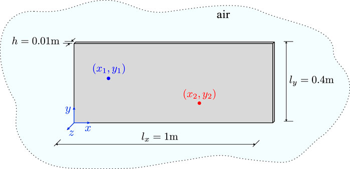
Figure 1. Simply supported rectangular plate immersed in air with the input force at point
The equation of motion Equation 1 is solved by modal analysis, which is based on the modal expansion of the deflection
Here,
This procedure yields the modal oscillator equations in terms of the modal coordinates
where damping has been added in the form of modal damping with modal damping ratio
In particular, an aluminum plate with the properties given in Table 1 is considered in this study. For this plate, Figure 2 shows the first six mode shapes according to Equation 3 up to a frequency of 750 Hz. The corresponding natural frequencies

Table 1. Vibroacoustic system parameters.
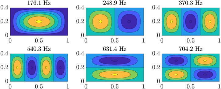
Figure 2. Mode shapes of the simply supported plate and corresponding natural frequencies in the frequency range of interest.
2.1.2 Acoustic radiation analysis using a nearfield approach
It is assumed that the vibrating plate is the only sound source and that the sound waves propagate in the positive direction of the
Once the surface vibration velocity distribution of the plate has been computed according to Section 2.1.1, the sound pressure
with
Here,
For the computation of the sound pressure field, the vibrating structure is discretized into elemental vibration sources Fahy (1989), Elliott and Johnson (1993). Here, elemental radiators based on a linearly spaced grid with an area
where
Since sound pressure is a field that varies with the observed point in space, it is common in acoustic studies to make use of the radiated sound power Fahy and Gardonio (2007) as position independent quantity. The time-averaged sound power
where the superscript * stands for the complex conjugate.
For the elemental radiators,
for a grid with element dimensions smaller than both the structural and acoustic wavelength, where
The radiated sound power can alternatively be computed by a set of radiation modes, a concept that is widely used in ASAC approaches Johnson and Elliott (1995), Elliott and Johnson (1993). These radiation modes are frequency-dependent, but independent from each other. Through them, radiation efficiencies can be computed, measures of how well the vibrating system produces sound for each of these modes. This approach is not followed here and is left for future studies.
2.1.3 Effects of reflections
To account for the effects of reflections from walls around the plate, the image source method is used Nagy et al. (2006). For each elemental radiator, the reflection is taken as an image source, where its distance is taken by mirroring this vibrating element with respect to the reflecting wall. Here, first order image sources are taken into account. Equation 6 must therefore be modified according to
where
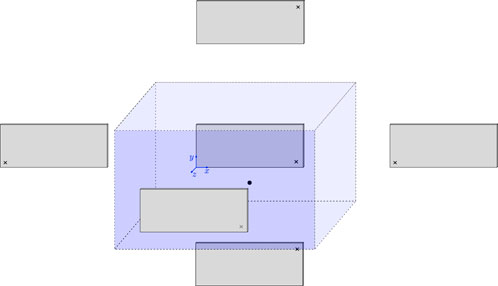
Figure 3. Image source method representation for a vibrating simply supported plate in a room.
2.2 Active control approaches
This section compares the effects resulting from AVC of the system shown in Figure 1. Different cases of proportional-integral-derivative (PID) controllers are implemented and their influence on the radiated sound pressure and sound power is discussed for a frequency range from 90 Hz to 750 Hz. Referring to Figure 1, at point
Proportional-integral-derivative controller is a feedback control-loop technique composed of three contributions Ogata (2010), Srivastava and Pandit (2016). The control effect of the proportional (P) element is directly proportional to the instantaneous error of the control system, allowing for immediate response correction. In this control setup, the control force generated by this element is proportional to the surface velocity. Meanwhile, the integral (I) element accumulates error over time, providing long-term stability by correcting even small persistent errors. It generates a restoring effect, which in this control system means the return of the structure to the target average position. The derivative (D) element reacts to the rate of change, which here corresponds to the rate of change of the velocity error, i.e., the acceleration. This is a predictive component that can prevent overshoot and improve the stability of the control system. A PID controller thus has the form
where
With
The block diagram of the control system described by Equation 12 is given in Figure 4, where

Figure 4. Block diagram of the closed loop control system.
The proportional element in Equation 11, i.e.,
3 Results
In this section, different cases of PID and DVF control are considered. The aim is to evaluate which type of AVC provides better performance in terms of sound propagation (here meaning sound reduction or at least lower levels of amplification) when structural vibration reduction is guaranteed.
3.1 Active vibration control of a simply supported plate
As shown in Figure 1, three scenarios are simulated with respect to the application point of the dynamic excitation:
The gains for each control case were chosen to result in a smaller magnitude of vibration amplitude throughout the frequency range of interest in all cases analyzed. They also were chosen to provide stable responses for the control system and the same order of magnitude for the forces required to apply control. Figures 5–7 show the Bode plots of the mobility frequency response functions for the uncontrolled and controlled systems for different combinations of the PID controller and DVF control.
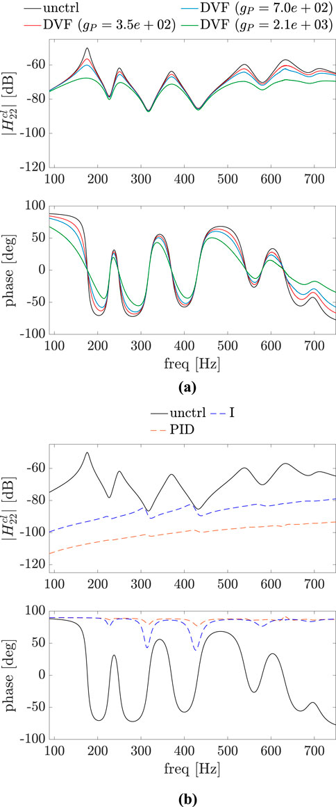
Figure 5. Bode plot of the uncontrolled (unctrl) and controlled systems, where the control point and the point of application of the force excitation are the same:
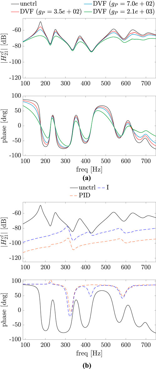
Figure 6. Bode plot of the uncontrolled (unctrl) and controlled systems, where the control point and the point of application of the force excitation are slightly different:
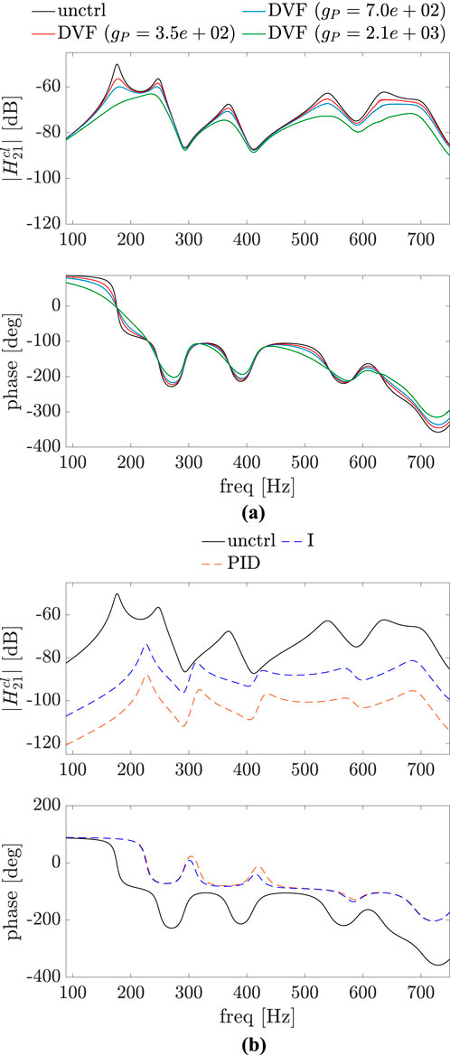
Figure 7. Bode plot of the uncontrolled (unctrl) and controlled systems, where the control point and the point of application of the force excitation are different:
For DVF, three different gains are considered:
For the complete PID case, the gains used are
3.2 Effects of active vibration control in acoustic radiation
In the following, the effects of these control approaches on acoustic radiation are examined. As mentioned previously, to compute the sound pressure by Equation 7, the influence of the velocities at all elemental sources must be taken into account. By doing this for both uncontrolled and controlled systems, it is possible to compare the influence of each AVC approach of Section 3.1 on the acoustic propagation. Furthermore, the sound power as given in Equation 9 is also computed and the reflections as described in Section 2.1.3 are discussed for uncontrolled system and different controlled approaches. Here, the mobility frequency response functions
3.2.1 System without reflections
Figures 8–10 show the Bode plots of the frequency response function
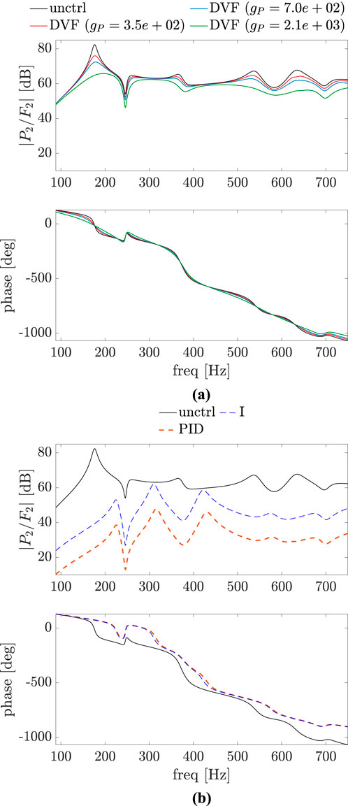
Figure 8. Bode plot of
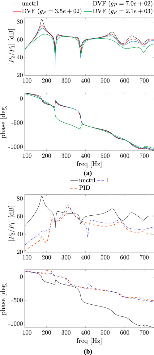
Figure 9. Bode plot of
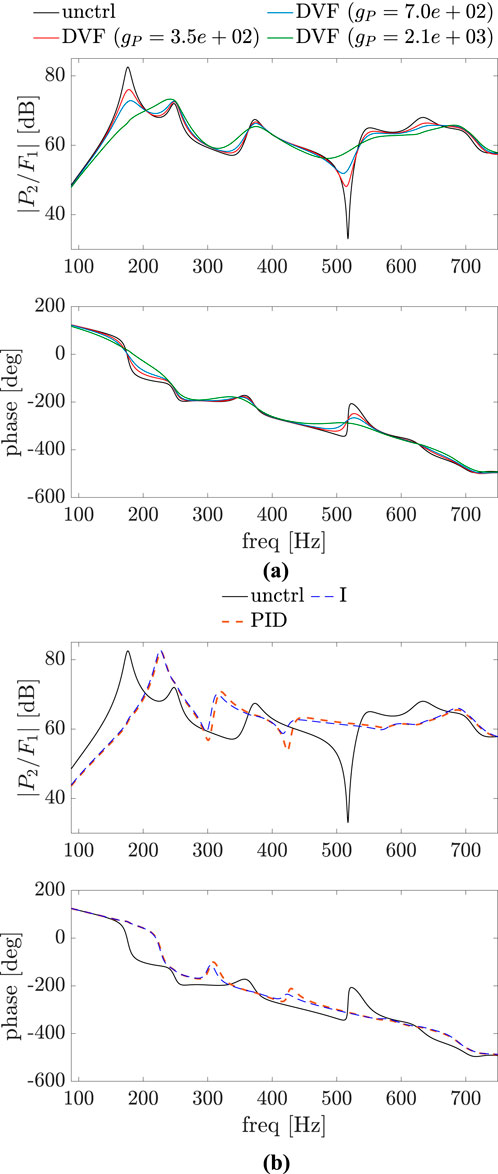
Figure 10. Bode plot of
A comparison of Figure 5 with Figure 8 shows that for all the control approaches there is a significant reduction in the magnitude of the sound pressure in the considered frequency range for this case of disturbance and control point at the same position on the plate. However, for a small deviation between these two points (Figures 6, 9) it is already noticeable that vibration reduction does not necessarily imply in sound pressure reduction for all the control approaches, as seen in Figure 9B in the frequency range between 240 Hz and 380 Hz. As the distance between the excitation force and control point increases, this is also true for DVF, as demonstrated in Figure 10. Also, the PID and I control approaches, which have a better performance in terms of structural vibration mitigation (see Figure 7), have a worse performance in terms of sound pressure propagation for frequencies between the natural frequencies of the uncontrolled plate.
To evaluate if this reduction/amplification of the sound pressure occurs for the whole
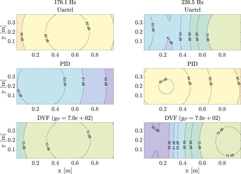
Figure 11. Magnitude
Using sound pressure directly as a measurement quantity in a feedback control setup is challenging due to its position dependency and the inherent time delay of the vibroacoustic system. The phase plots in Figures 8–10 show this delay due to the propagation of the sound wave in air. Compensation of time delay systems is an ongoing field of study and more details can be found in Wang (2012), Srivastava and Pandit (2016). In the current study, (direct) acoustic control is not considered.
Figures 12–14 show the magnitude
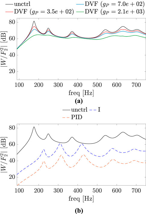
Figure 12. Magnitude plots of
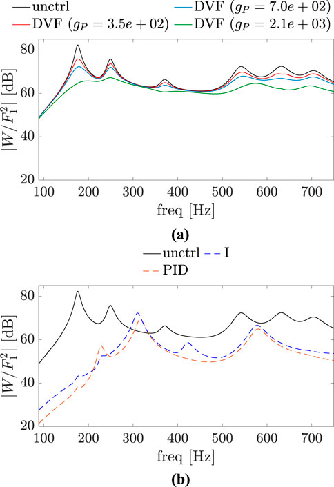
Figure 13. Magnitude plots of
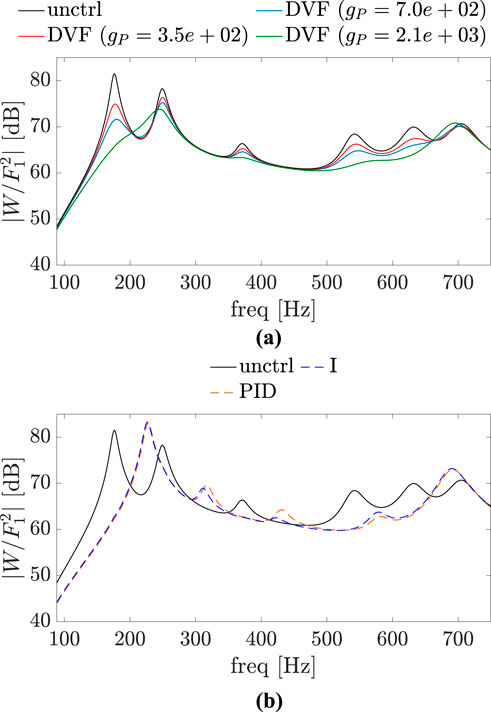
Figure 14. Magnitude plots of
The overall sound pressure level (SPL) at the observation point and the overall sound power level (SWL) for uncontrolled and controlled systems without considering reflections are also of interest. For the cases where excitation point and the control point are the same or very close, it can be seen in Figures 8, 9, 12, 13 that these overall levels decrease for all control approaches. However, this is not clear at first glance when these two points are far apart. SPL and SWL for this scenario are given in Table 2, where it is evident that the PID and I controllers result in a slight increase in both levels.
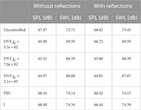
Table 2. Overall sound pressure level (SPL) at the observed point and overall sound power level (SWL) for uncontrolled and controlled systems.
3.2.2 System with reflections
To account for reflections, a constant
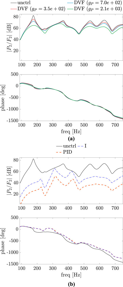
Figure 15. Bode plot of
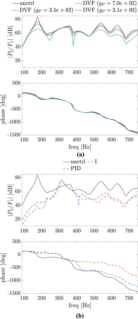
Figure 16. Bode plot of
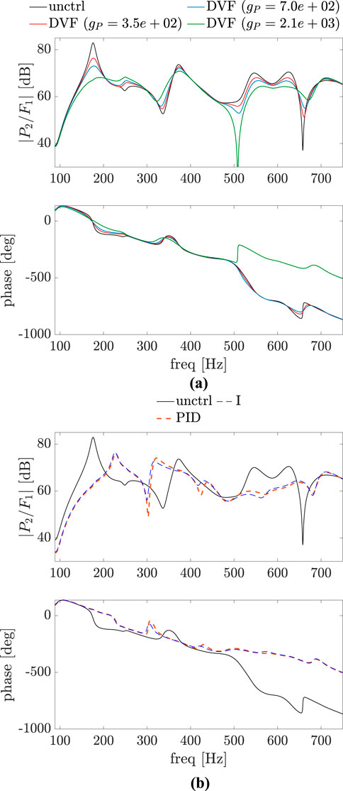
Figure 17. Bode plot of
Figure 18 shows the same configurations as in Figure 11, now with reflections considered. The magnitudes for all points in the plane for a vibrating frequency as the first damped natural frequency of the uncontrolled plate are reduced for both controlled approaches. However, for a frequency of 226.5 Hz this is not true for all points in the plane for the DVF approach, although the magnitude increases at the observed point.
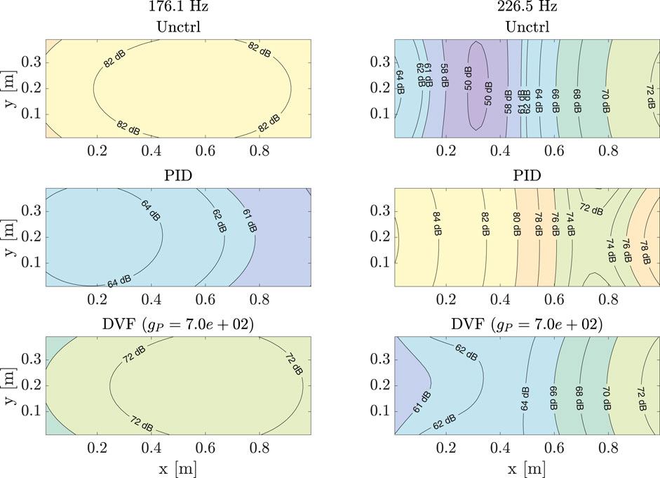
Figure 18. Magnitude
Figures 19–21 show magnitude plots of

Figure 19. Magnitude plots of
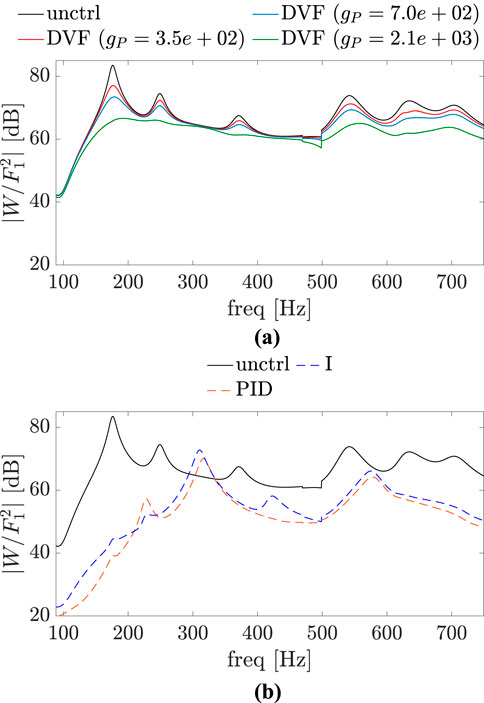
Figure 20. Magnitude plots of
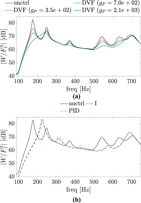
Figure 21. Magnitude plots of
The SPL at the observed point and the SWL for the system with reflections are also given in Table 2 for
4 Conclusion
The present paper deals with the acoustic radiation of a simply supported vibrating plate, where the aim was to compare different AVC strategies in order to reduce the resultant sound field in nearfield conditions. By analyzing these effects not only on the sound pressure but also on the sound power, it can be concluded that if the goal is to reduce the sound propagation at a specific excitation frequency such as one of the natural frequencies of the plate, all control options provide a good performance. On the other hand, if the objective is to achieve an overall reduction in the frequency range of interest, the DVF control approach can provide better results for structural and sound reduction as a set. For gain values where the shape of the magnitude plots remain close to the uncontrolled cases, the responses of the control system are predictable and provide reliable means to achieve sound reduction with and without reflections.
The contributions of this study can be summarized as follows:
The effects of different dimensions of the plate would also be of interest. With larger width and/or length, the natural frequencies of the system shift to lower values, while with larger thickness there is a shift to higher frequencies. The process of applying AVC does not change. Therefore, the effects of structural control should be similar, but now different gain values must be used for both PID and DVF control to achieve vibration mitigation. These new gain values must to be chosen in the same way to ensure stability of the control system, reduction of vibration, and the same order of magnitude of the forces required to apply control. In terms of sound propagation, the biggest difference is in the cases with reflections for the same room described in the paper, now with a larger plate. Pressure and power levels will increase with increasing width/length due to interference from reflected sound waves. However, the same conclusion should hold: if the shape of the magnitude plots remains close to the uncontrolled system, DVF provides predictable responses that can result in sound reduction. Furthermore, the analysis of other types of boundary conditions is suggested for future work to consider more realistic setups than the simply supported plate.
Data availability statement
The raw data supporting the conclusions of this article will be made available by the authors, without undue reservation.
Author contributions
NH: Software, Formal Analysis, Writing – original draft, Visualization, Investigation, Data curation. TF: Writing – review and editing, Methodology, Supervision, Conceptualization, Investigation. CA: Writing – review and editing, Supervision, Conceptualization, Resources.
Funding
The author(s) declare that financial support was received for the research and/or publication of this article. Open Access Funding provided by Universität Innsbruck.
Conflict of interest
The authors declare that the research was conducted in the absence of any commercial or financial relationships that could be construed as a potential conflict of interest.
Generative AI statement
The authors declare that no Generative AI was used in the creation of this manuscript.
Publisher’s note
All claims expressed in this article are solely those of the authors and do not necessarily represent those of their affiliated organizations, or those of the publisher, the editors and the reviewers. Any product that may be evaluated in this article, or claim that may be made by its manufacturer, is not guaranteed or endorsed by the publisher.
References
Alujević, N., Senjanović, I., Ćatipović, I., and Vladimir, N. (2019). The absence of reciprocity in active structures using direct velocity feedback. J. Sound Vib. 438, 251–256. doi:10.1016/j.jsv.2018.09.035
Baader, J., and Fontana, M. (2017). Active vibration control of lightweight floor systems. Procedia Eng. 199, 2772–2777. doi:10.1016/j.proeng.2017.09.529
Baumann, W. T., Ho, F.-S., and Robertshaw, H. H. (1992). Active structural acoustic control of broadband disturbances. J. Acoust. Soc. Am. 92, 1998–2005. doi:10.1121/1.405250
Díaz, I. M., and Reynolds, P. (2010). Acceleration feedback control of human-induced floor vibrations. Eng. Struct. 32, 163–173. doi:10.1016/j.engstruct.2009.09.003
Elliott, S. J., and Johnson, M. E. (1993). Radiation modes and the active control of sound power. J. Acoust. Soc. Am. 94, 2194–2204. doi:10.1121/1.407490
Fahy, F., and Gardonio, P. (2007). Sound and structural vibration: radiation, transmission and response. 2 edn. London: Elsevier.
Fuller, C. R. (1990). Active control of sound transmission/radiation from elastic plates by vibration inputs: I. Analysis. J. Sound Vibrafion 136, 1–15. doi:10.1016/0022-460X(90)90933-Q
Fuller, C. R., Hansen, C., and Snyder, S. (1991). Active control of sound radiation from a vibrating rectangular panel by sound sources and vibration inputs: an experimental comparison. J. Sound Vibrafion 145, 195–215. doi:10.1016/0022-460X(91)90587-A
Gattringer, H., Nader, M., Krommer, M., and Irschik, H. (2003). Collocative PD control of circular plates with shaped piezoelectric actuators sensors. J. Vib. Control 9, 965–982. doi:10.1177/10775463030098004
Genari, H. F., Mechbal, N., Coffignal, G., and Nóbrega, E. G. (2017). A reconfigurable damage-tolerant controller based on a modal double-loop framework. Mech. Syst. Signal Process. 88, 334–353. doi:10.1016/j.ymssp.2016.11.015
Guo, X., Volery, M., and Lissek, H. (2022). Pid-like active impedance control for electroacoustic resonators to design tunable single-degree-of-freedom sound absorbers. J. Sound Vib. 525, 116784. doi:10.1016/j.jsv.2022.116784
Hanagan, L., and Murray, T. (1997). Active control approach for reducing floor vibrations. J. Struct. Eng. 123, 1497–1505. doi:10.1061/(ASCE)0733-9445(1997)123:11(1497)
Hirschfeldt, N., Furtmüller, T., Adam, C., and Maderebner, R. (2024). Compensated velocity feedback for non-collocated active vibration control. Meccanica. doi:10.1007/s11012-024-01913-z
Johnson, M. E., and Elliott, S. J. (1995). Active control of sound radiation using volume velocity cancellation. J. Acoust. Soc. Am. 98, 2174–2186. doi:10.1121/1.413332
Leissat, A. W. (1973). The free vibration of rectangular plates. J. Sound Vib. 31, 257–293. doi:10.1016/S0022-460X(73)80371-2
Masnata, C., and Pirrotta, A. (2024). Optimal design of inerter-based absorbers with amplified inertance: from the improved tuned liquid column damper inerter (ITLCDI) to the improved tuned mass damper inerter (ITMDI) and improved tuned inerter damper (ITID). Meccanica. doi:10.1007/s11012-024-01834-x
Meirovitch, L. (1990). Dynamics and control of structures. (United States of America: John Wiley and Sons, Inc.).
Meirovitch, L., and Thangjitham, S. (1990). Active control of sound radiation pressure. J. Vib. Acoust. 112, 237–244. doi:10.1115/1.2930118
Nagy, A. B., Fiala, P., Márki, F., Augusztinovicz, F., Degrande, G., Jacobs, S., et al. (2006). Prediction of interior noise in buildings generated by underground rail traffic. J. Sound Vib. 293, 680–690. doi:10.1016/j.jsv.2005.12.011
Pérez-Aracil, J., Pereira, E., Díaz, I. M., and Reynolds, P. (2021). Passive and active vibration isolation under isolator-structure interaction: application to vertical excitations. Meccanica 56, 1921–1935. doi:10.1007/s11012-021-01342-2
Preumont, A. (2018). Vibration control of active structures: an introduction. 4 edn, 246. Cham, Switzerland: Springer.
Savioja, L., and Svensson, U. P. (2015). Overview of geometrical room acoustic modeling techniques. J. Acoust. Soc. Am. 138, 708–730. doi:10.1121/1.4926438
Schoeftner, J., and Krommer, M. (2012). Single point vibration control for a passive piezoelectric Bernoulli-Euler beam subjected to spatially varying harmonic loads. Acta Mech. 223, 1983–1998. doi:10.1007/s00707-012-0686-0
Shahabpoor, E., Reynolds, P., and Nyawako, D. (2011). “A comparison of direct velocity, direct, and compensated acceleration feedback control systems in mitigation of low-frequency floor vibrations,” in Dynamics of civil structures (Jacksonville, Florida, USA: Springer New York), 4, 177–187. doi:10.1007/978-1-4419-9831-6_19
Shin, C., Hong, C., and Jeong, W. B. (2013). Active vibration control of beams using filtered-velocity feedback controllers with moment pair actuators. J. Sound Vib. 332, 2910–2922. doi:10.1016/j.jsv.2012.12.037
Srivastava, S., and Pandit, V. S. (2016). A PI/PID controller for time delay systems with desired closed loop time response and guaranteed gain and phase margins. J. Process Control 37, 70–77. doi:10.1016/j.jprocont.2015.11.001
Wang, D. J. (2012). A PID controller set of guaranteeing stability and gain and phase margins for time-delay systems. J. Process Control 22, 1298–1306. doi:10.1016/j.jprocont.2012.05.019
Williams, E. G. (1999). Fourier acoustics: sound radiation and nearfield acoustical holography. Cambridge: Academic Press.
Wrona, S., Pawelczyk, M., and Qiu, X. (2020). Shaping the acoustic radiation of a vibrating plate. J. Sound Vib. 476, 115285. doi:10.1016/j.jsv.2020.115285
Keywords: active vibration control, feedback control, reflections, simply supported plate, sound radiation
Citation: Hirschfeldt N, Furtmüller T and Adam C (2025) Effects of active vibration control of simply supported plates on sound radiation. Front. Built Environ. 11:1601285. doi: 10.3389/fbuil.2025.1601285
Received: 27 March 2025; Accepted: 09 May 2025;
Published: 30 May 2025.
Edited by:
Chiara Masnata, University of Palermo, ItalyReviewed by:
Francesco Paolo Pinnola, University of Naples Federico II, ItalyMario Argenziano, University of Palermo, Italy
Copyright © 2025 Hirschfeldt, Furtmüller and Adam. This is an open-access article distributed under the terms of the Creative Commons Attribution License (CC BY). The use, distribution or reproduction in other forums is permitted, provided the original author(s) and the copyright owner(s) are credited and that the original publication in this journal is cited, in accordance with accepted academic practice. No use, distribution or reproduction is permitted which does not comply with these terms.
*Correspondence: Christoph Adam, Y2hyaXN0b3BoLmFkYW1AdWliay5hYy5hdA==