 Gao Kuiying1
 Li Zhibin
- 1Shendong Coal Branch, China Shenhua Energy Co., Ltd., Yulin, China
- 2CCTEG Xi′an Research Institute (Group) Co., Ltd., Xi′an, China
Aiming at the problem of long distance laying of casing for connected roadway directional borehole in underground coal mine, the bending capacity and passing capacity of casing were calculated and analyzed with the large diameter casing of Ф219 × 8.94 mm as the research object. The stress situation in the process of casing running was studied, and the supporting pipe jacking machine was developed and the engineering test was carried out. The results show that the limit dog leg of the casing string is 5.512°/30 m. The smaller borehole diameter has high requirements for dogleg control, and the larger borehole diameter increases the drilling difficulty. The preferred borehole diameter is 330 mm. The casing laying scheme of ' drill machine pulling back + pipe jacking machine pushing ' is put forward. The casing pushing and pulling process should be matched with thrust and tension. Focus on the design of horizontal telescopic guide rail propulsion system and mobile centralizer and clamping release system, the supporting pipe jacking machine was developed. The engineering test was carried out in the directional long borehole between Daliuta Mine and Huojitu Mine. The casing running and cementing achieved good results. The research results can provide reference for the implementation of similar projects.
1 Introduction
China’s coal resources are generally buried under complex geological conditions (Xu B. et al., 2022; Li et al., 2025; Kovalsky et al., 2025; Guo P. et al., 2021), with approximately 90% of coal resources suitable for underground mining methods (Leśniak et al., 2022; Li et al., 2022; Xu Y. et al., 2022). During underground coal mine operations, massive human and material resource investments are required to support safe operations at the mining face during pre-mining, mining, and post-mining stages, all of which rely on underground roadways. With the horizontal expansion of mining areas and the increasing vertical mining depths in large-scale underground coal mines (Liu et al., 2021; Li et al., 2023), the workload for inter-level and inter-district water supply and drainage, gas extraction and discharge, ventilation, and material supply has significantly increased annually. Solely relying on traditional underground roadways as transport channels results in higher costs and safety risks associated with roadway excavation, pipeline laying, and daily maintenance. Laying pipelines on the surface may be limited by topography and existing structures, and is often constrained by land acquisition, social coordination, and environmental and safety regulations, sometimes rendering surface pipeline laying unfeasible. With the advancement of underground horizontal directional drilling technology (Xiaoliang, 2023; Tian et al., 2024), precise interconnection of different roadways via underground directional boreholes to achieve water supply and drainage, gas extraction, ventilation, and material transport represents a new technical solution.
Casing long-distance laying technology is a key factor for enhancing the transport capacity and service life of boreholes used as conduits. Shi et al. (2019b) investigated the application of long directional borehole technology in methane extraction in Chinese coal mines, and found that the technique exhibited high gas drainage efficiency under complex geological conditions, effectively reducing methane emissions. Wang et al. (2012) systematically studied the development and application of directional drilling technology with measurement while drilling in underground coal mines, highlighting its significant role in disaster prevention, gas drainage, and geological assurance. Their research covered key techniques such as sliding guidance and compound directional drilling, as well as supporting equipment like relay measurement systems and wireless measurement systems. Field applications in Baode, Longwanggou, and Guqiao Mines validated the adaptability and high directional drilling capability of the technology in complex roofs and ultra-deep borehole construction. Shi et al. (2019a) addressed the issues of low success rate and slow speed in lowering ultra-long casings into underground directional boreholes in coal mines, proposing technical improvements such as straight drilling in the opening section, curvature control in the inclined section, active drill rod lowering via rig drive, and casing guiding; the maximum casing depth reached 168 m. Guo X. et al. (2021) conducted laboratory tests to analyze the sealing performance of grouting materials during the sealing process of gas drainage borehole sections. Wang et al. (2025) designed a new pressure-retaining sealing device and technique to address the shortcomings of the traditional “two plugs and one injection” method. Zhang et al. (2023) proposed a sealing technique combining polyurethane and expansive cement to overcome poor sealing quality, casing movement at the borehole opening, and water seepage and inrush issues in the surrounding coal body, which occurred with traditional cement mortar sealing in Chicheng Coal Mine. Sun et al. (2022) conducted a review and summary of the current status of underground gas drainage borehole sealing technology and outlined its future development directions.
At present, the lowering of casings in underground directional long boreholes in coal mines is mainly concentrated in the casing insertion and sealing process at the borehole opening, while the research on the casing laying process of long boreholes remains limited. This paper focuses on large-diameter casing with specifications of Ф219 × 8.94 mm, aiming to address the technical difficulties of current underground equipment and processes being inadequate for casing deployment. The study involves analysis of the passing capacity of large-diameter casing, development of laying procedures, and the design of a matching pipe-jacking machine, thereby investigating the laying process of casing in underground directional boreholes connecting roadways and supporting equipment, followed by engineering application.
2 Passing capacity analysis of large-diameter casing
In the process of full-length laying of large-diameter casing in underground coal mines, significant frictional resistance may occur. Whether the casing can be successfully laid requires detailed analysis. This analysis not only verifies the passing capacity of the casing but also provides a basis for curvature control of the borehole trajectory. Theoretical analysis is conducted to determine whether the Ф219 mm casing string can smoothly pass through borehole segments with diameters of Ф310 mm, Ф320 mm, Ф330 mm, Ф340 mm, and Ф350 mm, under extreme bending conditions, and to evaluate the corresponding critical curvature of the borehole trajectory.
2.1 Bending capacity of the casing
The bending capacity of the casing is first estimated (Zhao et al., 2024; Song, 2024), and the fitted bending curve obtained through MATLAB analysis is shown in Figure 1. The radius of curvature at the center point (X = 0) of this curve is calculated to be 312 m, representing the maximum radius of curvature at which the casing undergoes elastic limit bending deformation. Since the maximum stress at the selected point coordinate is 201.6 MPa, 312 m can be used as the reference maximum radius of curvature the casing can withstand under bending, corresponding to a critical dogleg severity of 5.512°/30 m.
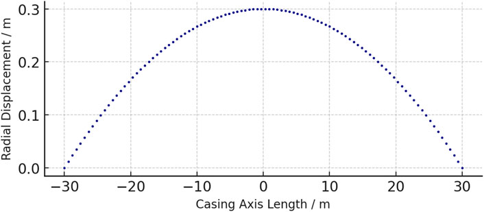
Figure 1. Fit curve.
Figure 1 illustrates the fitted curve of the Ф219 × 8.94 mm casing under bending stress. It can be observed that at the center of the curve (X = 0), the casing reaches its maximum stress value of 201.6 MPa, corresponding to a radius of curvature of 312 m. This point represents the state at which the casing is about to enter its elastic limit; further bending beyond this point would result in plastic deformation. The increasing trend of stress in the figure reflects the casing’s gradually decreasing capacity to resist bending deformation as curvature increases. Especially when the radius of curvature is less than 320 m, the stress increases significantly, indicating that more severe bending leads to greater localized stress concentration, which is more likely to cause yielding or damage. It should be clarified that 201.6 MPa is not the intrinsic yield strength of the material, but rather the maximum equivalent stress obtained from the bending analysis model under the critical curvature radius of 312 m. This value represents the threshold at which the casing approaches its elastic limit in terms of geometric bending constraints. The actual yield strength of the casing steel is 552 MPa, which is significantly higher. Therefore, in Table 2, the note “Elastic limit reached–Yes” indicates that under this curvature condition the casing stress has reached the calculated elastic limit in the model, but not the material’s true yield strength or failure threshold.
2.2 Influencing factors of casing obstruction in borehole segments
To verify whether the Ф219 mm casing string can smoothly pass through open-hole segments with specific diameters (Ф310 mm, Ф320 mm, Ф330 mm, Ф340 mm, Ф350 mm) under its extreme bending condition, it is considered that the curved build section is the primary part affecting the casing’s bending deformation. The final selection of the curved borehole section length is set at 30 m as required. Since the casing length must exceed the borehole section, the casing is designed to be 40 m in length, consisting of four welded sections of 10 m each. As the casing enters the curved borehole section, the unentered portion may become inclined; therefore, a near-horizontal section of 30 m is constructed to constrain the casing’s movement. Thus, a 60 m long borehole model is established, comprising a 30 m curved section and a 30 m near-horizontal section, and the casing model is 40 m in length. The borehole segment is fully constrained, and friction exists between the casing and the borehole wall.
Statistical analysis of the simulation results reveals that the influencing factors of casing obstruction in borehole segments include the dogleg severity of the curved section, the friction coefficient, the magnitude of the applied load, and the load increase rate. Using the single-variable method, parameter values are randomly selected from defined value ranges. The analysis of the casing’s movement process in the borehole shows three possible outcomes, as listed in Table 1.

Table 1. Comparison of simulation results.
Result 1: The casing encounters obstruction within the curved borehole section without reaching the elastic limit.
Result 2: The casing successfully passes through the curved section without reaching the elastic limit.
Result 3: The casing reaches the elastic limit while passing through the curved section.
In this study, to comprehensively evaluate casing passability under different borehole diameters and curvature conditions, numerical models were constructed for each diameter (Ф310, Ф320, Ф330, Ф340, Ф350 mm) combined with curvature radii ranging from 300 to 320 m. For each combination, ten working conditions were simulated with varying friction coefficients (0.15–0.30) and loading rates (0.5–2.0 m/min), reflecting potential field variations. From the numerical analysis in Table 2, it can be seen that as the borehole diameter gradually increases, the maximum stress experienced by the casing under the same curvature radius condition significantly decreases. For instance, when the borehole diameter increases from Φ310 mm to Φ330 mm, even with minimal curvature change, the stress level drops from 202.8 MPa to below 199.2 MPa, indicating that a larger borehole diameter leads to reduced contact friction between the casing and the borehole wall, thereby lowering the degree of restriction on casing bending deformation. In addition, larger borehole diameters provide more space for cuttings removal, which enhances cuttings discharge efficiency and indirectly reduces casing advancement resistance.
However, increasing the borehole diameter also results in extended drilling time, decreased borehole wall stability, and increased construction costs, thus it cannot be expanded indefinitely. By comprehensively considering casing stress control and on-site construction capability, Φ330 mm is selected as the optimal final borehole diameter. This selection not only ensures casing passability but also reduces the difficulty of trajectory control and the risk of casing yielding, forming a relatively reasonable construction parameter range. Furthermore, from the “Casing Reaches Elastic Limit” column, it is evident that when the borehole diameter is less than 320 mm, nearly all dogleg configurations cause the casing to enter the elastic limit or even the yield zone, which is detrimental to safe deployment. Therefore, small-diameter drilling should be strictly avoided in field applications.

Table 2. Effect of curvature radius on stress under different apertures.
2.3 Limit curvature calculation
By varying the curvature of the bent borehole section under different borehole diameters, the limit curvature through which the casing can pass is calculated. Table 2 presents the curvature values corresponding to two motion states of the curved borehole section under different borehole diameters: casing passing without reaching the elastic limit, and casing passing while already reaching the elastic limit.
Based on the calculated results in the table, the optimal final borehole diameter can be selected under different dogleg conditions to ensure smooth casing passage. It is important to note that one of the assumed conditions in the simulation calculation is that cuttings inside the borehole are completely removed, and the resistance during casing placement is mainly due to borehole wall friction. However, in actual conditions, it is impossible to remove all cuttings completely. Therefore, in addition to the wall friction generated by the smooth borehole wall, the friction caused by accumulated cuttings inside the borehole should also be considered. Accordingly, larger values should be considered when selecting the final borehole diameter and dogleg severity control parameters. As shown in Table 2, the casing can possibly pass when the final borehole diameter exceeds Φ320 mm, but smaller diameters require stricter dogleg control, and larger diameters increase construction difficulty. Therefore, a final borehole diameter of Φ330 mm is preferred.
It should be noted that in the present simulations, it was assumed that all cuttings inside the borehole were completely removed, a condition that is difficult to achieve under real construction circumstances. In practice, residual cuttings increase friction between the casing and borehole wall, which may lead to higher push–pull forces and localized stress concentrations, thus affecting the smooth installation of the casing. As a result, the simulations may slightly underestimate the stress levels encountered in the field. Therefore, engineering design and field operations should account for this by considering flushing capacity, cuttings removal efficiency, and borehole stability, ensuring that adequate safety margins are reserved.
3 Borehole trajectory design and control
In order to achieve long-distance deployment of large-diameter casing in underground directional drilling, borehole trajectory design and control is one of the key links. The drilling trajectory not only directly affects the successful insertion of the casing but also determines the bending stress and friction distribution during deployment, which has a decisive impact on construction risk, safety, and engineering quality. Especially under complex geological conditions or in long-distance build sections, poor trajectory control is prone to cause casing deformation, obstruction, or even failure. Therefore, based on a full understanding of casing passage capacity, it is necessary to scientifically design the borehole trajectory and adopt reasonable build and hold control methods to ensure that the casing can be smoothly deployed along the predetermined path, providing fundamental support for subsequent casing advancement and borehole stabilization.
3.1 Design basis
The application of underground directional drilling in coal mines has become relatively mature, and the general principles and basis for borehole design will not be repeated here. In order to ensure that the casing can be deployed throughout the entire borehole section after completion, stricter requirements on dogleg severity must be proposed in the trajectory design.
Based on the analysis in Table 2, under a final borehole diameter of 330 mm, the critical dogleg severity for the passage of an outer diameter 219 mm casing is 5.512°/30 m. This imposes stricter trajectory control requirements on the commonly used underground directional drilling tools, and this critical dogleg severity represents the threshold value for the entire borehole.
According to the characteristics of directional drilling between interconnected underground roadways, the terminal hole location is essentially fixed. Based on the terminal position and curvature requirements of the trajectory, the starting point can be back-calculated. Combined with the actual space conditions of the underground excavation, the drill site is optimally selected, and the final design trajectory is determined.
3.2 Control method
Near-horizontal long-distance directional drilling generally adopts a compound directional drilling process of “sliding build + rotary hold.” When trajectory adjustment is needed during drilling, the “sliding build” mode is applied: the drill rod is held stationary in rotation, and forward movement is achieved by sliding, with the bottom-hole screw motor solely driving the bit to rotate and break the rock, continuously building inclination. When no trajectory adjustment is needed, the “rotary hold” mode is applied: the rig rotary drive rotates the drill rod forward, working in combination with the bottom-hole screw motor to jointly drive the bit to rotate and break the rock, thereby achieving stable directional drilling.
During the sliding build process, the trajectory of the borehole is altered by adjusting the tool face angle of the screw motor to change the direction of bit cutting, specifically modifying the inclination and azimuth angles of the borehole trajectory (Figure 2). When the tool face is in region Ⅰ or Ⅳ, the trajectory tends to increase in inclination; when in region Ⅱ or Ⅲ, the trajectory tends to decrease. When the tool face angle Ω = 0° or 180°, the trajectory variation corresponds to the maximum inclination build-up or drop rate. When the tool face is in region Ⅰ or Ⅱ, the trajectory shows a trend of increasing azimuth; in region Ⅲ or Ⅳ, it shows a decreasing trend. When Ω = 90°, the azimuth build-up is at its maximum; when Ω = 70°, the azimuth drop is at its maximum.

Figure 2. The effect of tool face angle on inclination and azimuth.
Figure 2 illustrates the effect of tool face angle on the variation of inclination (θ) and azimuth (α). When the tool face is in quadrant I or IV, the inclination θ increases; when in quadrant II or III, the inclination θ decreases. At tool face angles of 0° or 180°, the rate of inclination change reaches its maximum. Meanwhile, when the tool face is in quadrant I or II, the azimuth α increases; when in quadrant III or IV, the azimuth α decreases. Specifically, 90° corresponds to the maximum azimuth build-up rate, while 270° corresponds to the maximum azimuth drop rate. This concise explanation helps readers quickly grasp the specific role of tool face angle in trajectory control. During the rotary hold process, the drill rig’s power head drives the drill rod rotation, serving two functions: first, to provide the cutting power for the bottom-hole bit to fracture the rock; second, to cause periodic variation in the inclination-building force of the bottom-hole screw motor, thereby suppressing its directional build function and enabling the borehole to maintain a relatively stable attitude and extend along a near-straight trajectory.
3.3 Control effect
By reasonably coordinating alternating operations of sliding build and rotary hold, and pre-estimating build intensity and hold effect based on formation characteristics, the trajectory is controlled to maintain a certain dogleg severity while drilling toward the target point. The actual drilling achieved both precise target-hitting and curvature control requirements, with a target center deviation of 0.36 m and a maximum dogleg severity of 5.505°/30 m. The variation of dogleg severity along the entire borehole trajectory is shown in Figure 3.

Figure 3. Distribution of dog leg degree in the entire hole section.
4 Large-diameter casing installation process
4.1 Casing installation scheme
According to the capacity of existing high-power drilling equipment in underground coal mines, the drilling rig can generate an actual pullback force of approximately 30 tons and a thrust force of about 25 tons. Due to the influence of residual cuttings that cannot be completely removed from the borehole and the high curvature sections unavoidably formed during the actual drilling process for connection alignment, relying solely on the drilling rig for pushing or pulling the casing entails high risk. Therefore, auxiliary equipment must be employed for casing installation. Based on this, a casing installation scheme combining “drilling rig pullback + pipe jacking machine thrust” is proposed, as illustrated in Figure 4.

Figure 4. Schematic diagram of casing laying process.
Compared with conventional single-direction pulling or pushing methods, the combined scheme of “drill rig back-pulling + pipe-jacking pushing” demonstrates higher reliability and safety in long-distance, large-diameter casing installation. Single pulling under high friction conditions is prone to casing sticking and excessive stress concentration, while single pushing is limited by insufficient thrust, making it difficult to ensure smooth full-length casing placement. The combined method allows pulling and pushing forces to complement each other during different construction stages, effectively reducing local resistance and stress peaks while improving controllability and stability of the installation process. This approach balances construction efficiency with safety, highlighting its distinct technical advantages and practical value.
4.2 Stress distribution analysis of the casing string during installation
4.2.1 Stress analysis
Since the casing length is far greater than its outer diameter, the casing can be approximated as a spatial curve. Taking the borehole collar at the excavation pit as the origin, a coordinate system is established with true north as the N-axis, true east as the E-axis, and the plumb direction as the Z-axis. The borehole trajectory can be fitted to form a spatial curve, and during the casing installation process, the casing can be regarded as a continuous curve that moves along the spatial trajectory of the borehole, with the same curvature path as the borehole trajectory.
When the casing comes into contact with the borehole wall, it is assumed that the section of casing under study is located at an arbitrary position within the borehole. Due to the bending and constraint effects of the borehole, a certain degree of bending will occur. The inclination angle of the borehole at the front endpoint is Qi+1, and the azimuth angle at the front endpoint is ψi+1; the inclination angle at the rear endpoint is Qi, and the azimuth angle at the rear endpoint is ψi. The unit length of the pipe string is Li. The stress condition of the casing is shown in Figure 5.

Figure 5. Schematic diagram of stress on casing micro elements.
To enable a more accurate analysis of the casing unit segment, the following assumptions are made.
1. The borehole diameter and curvature remain constant, and the effect of borehole deformation is not considered;
2. Shear forces on the cross-section of the casing string are neglected;
3. Contact between the casing and the borehole wall is considered as line contact;
4. The deformation curve of the casing is assumed to be completely consistent with the borehole axis;
5. The variation in casing joint thickness is ignored, and the linear density and cross-sectional area of the casing are assumed to be uniform;
6. Lateral shear forces at both ends of the casing are not considered.
Under these assumptions, the primary forces acting on a micro-element of the casing include: the self-weight of the casing qi, Li, the support force from the borehole wall Ni, and the frictional resistance from the borehole wall Fi. The forces at both ends of the casing segment are Qi and Qi+1, respectively. A differential equation is established based on mechanical equilibrium, and the stress distribution along the casing is obtained through numerical calculation.
To further reveal the actual stress distribution pattern of the casing within the borehole, a refined mechanical simulation is conducted using Finite Element Analysis (FEA) based on the simplified analytical model. A typical curved segment corresponding to the casing passing through the critical dogleg severity (5.512°/30 m) is selected for study. A 3D casing–borehole wall contact model is developed using ABAQUS FEA software, as shown in Figure 6. In the finite element model, the casing material is modeled as elastoplastic, based on the constitutive relation of steel. The elastic modulus of the casing material is 210 GPa, the Poisson’s ratio is 0.3, and the yield strength is 552 MPa. The contact between the casing and the borehole wall is modeled using a Coulomb friction model with a friction coefficient of 0.25. The boundary condition assumes the borehole wall is fully constrained, with axial pushing or pulling load applied at one end of the casing while the other end remains free, to simulate field construction conditions.
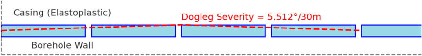
Figure 6. Finite element model of casing–borehole contact.
Based on the FEA simulation results, the stress contour and displacement distribution of the locally bent casing segment are obtained (as shown in Figure 7). The simulation indicates that at the point of maximum curvature, significant stress concentration occurs on the inner side of the casing, with the maximum equivalent stress reaching approximately 70% of the material’s yield strength, which remains within the safe range; meanwhile, the outer side of the casing is subjected to tensile stress. The simulation results further validate the Euler-Bernoulli beam theory formula, as shown in Equation 1:
where σmax is the maximum bending stress on the beam cross-section; M is the bending moment; d is the outer diameter of the casing; and I is the moment of inertia of the casing cross-section. A comparison with the theoretical formula reveals good agreement between numerical simulation and theoretical calculation, indicating that the simplified assumptions and numerical simulations adopted in this study possess high engineering applicability and reliability.
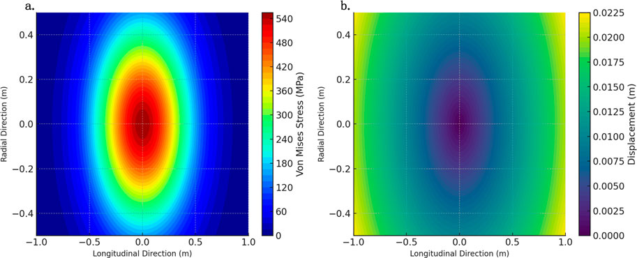
Figure 7. Stress contour and displacement distribution of the locally bent casing segment. (a) Stress distribution in casing (FEA). (b) Displacement distribution in casing (FEA).
Figure 7a shows the Von Mises stress contour of the locally bent casing segment. The results indicate that the stress concentration area is mainly distributed in the central region of the casing bend, forming an obvious elliptical distribution. The maximum stress is approximately 540 MPa, which approaches the yield strength limit of the casing material, indicating that this region is the most prone to plastic deformation during installation. As the distance from the central region increases, the stress rapidly decreases to below 180 MPa, presenting a significant gradient distribution trend.
Figure 7b illustrates the displacement distribution of the locally bent casing segment. It shows that the maximum radial displacement of the casing appears near the edge of the bending segment, with a maximum displacement of about 0.0225 m. The central region of the casing exhibits the smallest displacement, close to zero. The displacement field distribution is relatively uniform, and the overall displacement remains within the engineering allowable range, indicating that the overall stiffness of the casing is sufficient to meet the bending deformation requirements during the actual installation process.
4.2.2 Neutral point treatment
Stress analysis reveals that there is a specific point on the casing string where no tension or compression occurs, and the stress is zero. This point is referred to as the neutral point. During actual construction, the casing string is subjected to both pulling force from the drilling rig and pushing force from the pipe-jacking machine, causing the position of the neutral point to fluctuate frequently. According to statistical data from field monitoring [see (Table 3)], the neutral point of the casing can fluctuate within a range of 0.5–1.2 m at a frequency of 2–3 times per minute during different construction stages. The casing near the neutral point is subjected to alternating loads, which easily leads to fatigue yielding, thereby reducing the structural strength and service life of the casing. Therefore, to enhance the fatigue resistance and structural safety in this region, reinforcing ribs should be welded, or thick-walled casings should be adopted within the neutral point fluctuation zone to ensure smooth engineering construction. In practical applications, when the construction environment is spatially constrained and operational convenience is a priority, welded reinforcing ribs are preferred, as they allow flexible implementation and controllable reinforcement positions. Conversely, in borehole sections with complex stress conditions, significant alternating loads, and higher requirements for overall strength, thick-walled casings are more suitable, providing enhanced bending resistance and fatigue performance. Monitoring employed DYLF-102 strain-type load cells (range 0–500 kN, accuracy 0.5%) and XH-25 torque sensors (range 0–20 kN m, accuracy 0.3%) to capture the load variations of the casing during alternating push–pull operations, combined with displacement sensors for neutral point position calculation. The data acquisition frequency was set at 1 Hz, with a measurement error controlled within ±2%. All data were processed with filtering and outlier removal before statistical analysis.

Table 3. Field monitoring data of casing neutral point fluctuations.
4.3 Thread design and strength verification of casing
Considering the convenience of threaded connections, the preferred Φ219 mm casing adopts a T-type thread. Both ends of the casing are female threaded, while the coupling is male threaded on both sides. The coupling has an outer diameter of 219 mm and is internally thickened, with chamfers on both ends of the thickened short section to maintain a relatively smooth internal diameter.
For the specific design parameters of the thread type, strength verification is conducted through simulation calculations and pull-out tests of the threaded connection. Additionally, the casing material undergoes physicochemical testing to ensure compliance with N80 grade material standards.
Within the rated range of pushing and pulling forces, numerical simulations are conducted based on the actual drilling trajectory. The pushing and pulling force ranges during the casing installation process are pre-designed to ensure minimal fluctuation in the neutral point position and enhance the overall strength of the casing.
5 Development of matching pipe-jacking machine
Focusing on the casing installation scheme, a matching pipe-jacking machine was developed. The pipe-jacking machine adopts a split structure, consisting of a box-type hydraulic pump station and a skid-mounted jacking unit, which facilitates transportation and layout at the well site. Through the design and matching of the box-type hydraulic pump station, the hydraulic system layout, and hydraulic pipeline arrangement, the overall hydraulic system was completed. The system is powered by a diesel engine, eliminating the need for electrical connections during operation.
A skid-mounted horizontal telescopic jacking unit, trolley track support system, and mobile casing centralizer were designed, forming a horizontal telescopic cylinder with a wire rope speed-increasing jacking system supported by rails. This setup enables a long stroke jacking process within a short machine body transport length, meeting the operational requirements for installing 10 m long casing sections.
A high-torque clamping and breakout unit was designed to enable strong make-up and break-out operations of φ219 mm threaded casing joints. Ultimately, a ground-based large-diameter long-casing horizontal pipe-jacking machine was developed, enabling safe and efficient horizontal jacking installation of 10 m long φ219 mm threaded casing. The structure of the pipe-jacking machine is shown in Figure 8.
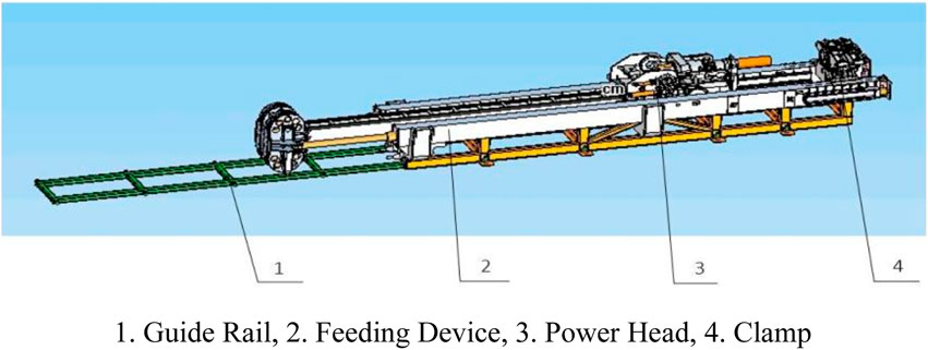
Figure 8. Schematic diagram of pipe jacking machine structure.
6 Engineering application
6.1 Project overview
A directional long borehole was constructed between the 1-2 coal roadway of the Daliuta Mine and the roadway of the Huojitu Mine, followed by full-length casing installation and borehole stabilization, to serve as a long-term and stable water diversion channel. A schematic diagram of the borehole layout cross-section is shown in Figure 9.
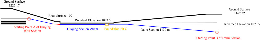
Figure 9. Cross sectional view of the location of large diameter water conveyance boreholes in Daliuta Huojitu.
The field test was conducted between the Daliuta and Hojitu mines in the Shendong mining area, with a burial depth of approximately 600–800 m. The strata consisted mainly of interbedded sandstone and siltstone, with moderate pore water pressure. To ensure representativeness and reliability, the casing installation process was repeated three times under identical borehole conditions, with consistent construction parameters. During each test, load cells and displacement sensors were employed to monitor pulling force, pushing force, and casing displacement in real time, with dual-equipment verification at critical stages to minimize systematic errors. Data acquisition was performed at a frequency of 1 Hz, and quality control was achieved by comparing results across different repetitions. Outlier removal and statistical consistency checks were applied to all monitoring data, ensuring accuracy and reliability of the test results.
6.2 Borehole structure
The water transfer borehole adopts a two-stage borehole structure. The primary section is mainly intended for installing the collar pipe, supporting the roadway wall around the borehole opening, and installing a water control valve. The secondary section connects to the foundation pit and is used for casing installation. See Table 4 for details.
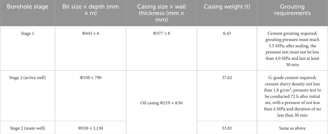
Table 4. Structure of drilling hole body.
6.3 Wellhead device
During the field test, drilling was performed using a ZDY12000LD full-hydraulic underground directional drilling rig, with a rated torque of 12 kN m and a maximum drilling depth of 1,500 m. Borehole trajectory measurements were conducted with a CJT3000 measurement-while-drilling inclinometer, providing an inclination accuracy of 0.1° and azimuth accuracy of 0.25°. Stress and push–pull force monitoring employed DYLF-102 strain-type load cells with a range of 0–500 kN and an accuracy grade of 0.5%, combined with an XH-25 torque sensor (range 0–20 kN m, accuracy 0.3%) for real-time acquisition of rig and casing loads. The data acquisition system was configured at a frequency of 1 Hz, with dual-channel recording to ensure redundancy and enhance the accuracy and stability of the monitoring results.
6.3.1 Wellhead safety device
A reducing tee and a DN150 gate valve are used to ensure smooth return of cuttings during reaming and to allow timely closure of the wellhead in the event of encountering large water inflows. The wellhead casing is installed first and subjected to a pressure test. Before formal construction begins, a wellhead safety gate valve must be installed to ensure water discharge control.
The installation and use of the wellhead device are shown in Figure 10.
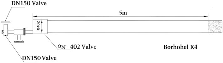
Figure 10. Installation and use diagram of orifice device.
6.3.2 Wellhead casing sealing standard
After a 48-hour setting period for the grouted section, a pressure test is conducted by injecting water into the borehole using a mud pump. The pressure is maintained at 4.0 MPa for 30 min, during which the borehole wall and the area around the wellhead casing are observed for any signs of leakage. The pressure drop should be less than 0.5 MPa within 30 min. If no leakage is observed and the pressure holds, the sealing is considered qualified. If leakage occurs and the pressure drop exceeds 0.5 MPa, further grouting is required until the pressure resistance standard is met.
6.4 Casing installation and borehole sealing
Before casing installation, the pulling and pushing force parameters are pre-calculated based on the actual borehole trajectory. Bevels are machined at the thread steps of the casing and the short joints. After the casings are connected, weld seams and stiffening ribs are added at the threaded joints. Standard petroleum casings with specifications Φ219 × 8.94 mm are used during construction, with a unit weight of approximately 47.62 kg/m. A single casing pipe (typically about 10 m long) weighs about 476.2 kg. The casings are lifted with a crane and lowered into the borehole with the help of the pipe-jacking machine.
Before lowering the casing, a drift operation is performed to restore the borehole wall and clear accumulated cuttings. According to the borehole structure design, the drift assembly consists of a Φ114 mm drill rod and a Φ219 mm casing short joint. Four reinforcing ribs are symmetrically installed at the connections between the drill rod and the casing short joint to reinforce both ends of the drift tool. The outer diameter of the ribs is Φ330 mm. The ribs are integrally welded to the drill rod to ensure weld quality, and a central support is added to enhance the tool’s rigidity. The structure of the drift tool is shown in Figure 11.

Figure 11. Φ 330 mm large diameter drift gauge (reverse reaming).
Before casing installation, a special traction short joint was developed to reliably connect the Φ114 mm drill rod with the casing. The traction device is required to withstand axial tensile forces while allowing self-rotation, ensuring that during the casing back-pulling process, the rotational torque differences caused by friction between drill rods and casings of different outer diameters are naturally neutralized.
Borehole sealing is carried out using the annular cement slurry injection method, with large-displacement cement slurry pumped by an oilfield cementing truck. According to the different drilling profiles of the active well section and the large well section:
For the active well section, a 6 m annular space at the low elevation point of the pit is sealed and a grouting pipe is pre-embedded. Cement slurry is injected from the pit into the casing annulus until the cement slurry returns from the active wellhead casing.
For the large well section, a 6 m annular space is sealed at both the pit and the underground wellhead, and a grouting pipe is pre-embedded. Before injecting cement slurry from the pit into the casing annulus, the annulus is filled with clean water. Cement slurry is injected through the annular grouting pipe at the pit (with the underground annular grouting pipe valve opened). Initially, clean water flows out from the annulus, followed by the cement slurry. Once cement slurry flows out, the underground annular valve is closed for setting.
The schematic diagrams are shown in Figures 12, 13. G-grade cement is used for cementing, with a cement slurry density of no less than 1.8 g/cm3. The amount of cement is prepared based on a borehole enlargement ratio of 1.5. After a 72-hour setting period, a pressure test is conducted with a pressure not less than 4 MPa and a duration of not less than 30 min. By adopting the predetermined casing installation scheme, full-length casing installation is achieved, the borehole is successfully sealed, and the pressure test meets the requirements, resulting in excellent construction performance.
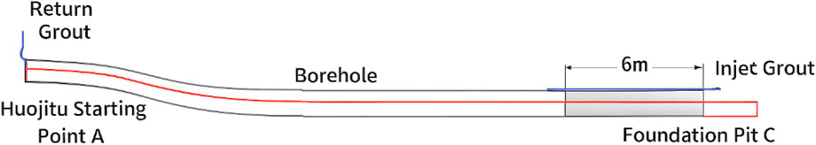
Figure 12. Schematic diagram of live well drilling and cementing.

Figure 13. Schematic diagram of large well drilling and cementing.
In recent years, the application of machine learning in geotechnical engineering and materials science has expanded, providing new perspectives for modeling and prediction in complex systems. In the study of casing installation and borehole stability, purely mechanical calculations reveal stress distribution but remain limited in predicting long-term stability and material optimization. By leveraging machine learning, multi-source data can be trained and modeled to predict casing loads under complex geostress environments, thereby supporting long-term stability assessments. Furthermore, for cementing materials, traditional optimization of slurry formulations relies heavily on empirical approaches and limited experiments, which can be inefficient. AI-based multi-component material optimization methods, however, can rapidly screen and predict optimal mix proportions from large datasets, significantly improving cementing quality and durability. Previous studies have shown that machine learning can effectively predict material strength properties and enable intelligent optimization of composite systems (Xu B. et al., 2022; Li et al., 2025). Therefore, integrating casing placement mechanics with machine learning–based material optimization not only improves the engineering design framework but also aligns with the global trend toward digitalization and intelligent mining engineering, enhancing the scientific novelty of this work.
7 Conclusion
This study addresses the technical bottlenecks encountered in the long-distance deployment of casing through directional drilling between underground roadways in coal mines. It conducts a systematic investigation focusing on the passability of large-diameter casing, trajectory control, laying processes, and supporting equipment, and verifies the feasibility and advancement of the proposed methods in practical engineering. The following conclusions are drawn.
1. Through theoretical calculation and simulation analysis, the critical dogleg severity for Φ219 × 8.94 mm casing during underground borehole deployment is determined to be 5.512°/30 m, providing a key parameter basis for safely passing curved sections.
2. Simulation-based evaluation of casing stress responses under various borehole diameters reveals that a final borehole diameter greater than Φ320 mm allows successful passage. Considering construction cost and trajectory control difficulty, a diameter of 330 mm is recommended as the optimal deployment parameter.
3. An innovative “drill rig back-pulling + pipe-jacking machine forward-pushing” combined operation scheme is proposed to address the limitations of unidirectional pulling or pushing capacity during ultra-long casing deployment. For the first time, the alternating stress vulnerability near the neutral point is clarified, and reinforcement segments or thick-walled pipe sections are recommended to enhance structural reliability.
4. To overcome underground operational constraints such as limited space and lack of accessible power sources, a split skid-mounted pipe-jacking machine is independently developed. It features horizontal telescopic rails, multi-point centralization, and automatic gripping and unthreading functions, significantly improving pushing efficiency while reducing construction risks.
5. A directional drilling long-distance casing deployment and borehole cementing engineering trial was successfully conducted between the Daliuta and Huojitu coal mines. Accurate trajectory control across the full borehole length, smooth casing installation, and tight cement sealing were achieved, marking the first practical application of this technology in complex inter-mine connection projects, demonstrating strong prospects for promotion and replication.
The research results not only overcome the “long distance, high curvature, heavy thrust” challenges in underground directional casing deployment but also establish a replicable and scalable engineering system in terms of equipment integration and construction management. This provides new insights and technical support for the efficient development of underground energy transport, ventilation, and drainage systems in China.
Data availability statement
The original contributions presented in the study are included in the article/supplementary material, further inquiries can be directed to the corresponding author.
Author contributions
GK: Writing – original draft. LG: Writing – original draft, Writing – review and editing. LZ: Writing – original draft, Writing – review and editing. MH: Writing – review and editing. HY: Writing – original draft. LX: Writing – original draft, Writing – review and editing.
Funding
The author(s) declare that no financial support was received for the research and/or publication of this article.
Conflict of interest
Authors GK, LG, HY were employed by China Shenhua Energy Co., Ltd. Authors LZ, MH, LX were employed by CCTEG Xi′an Research Institute (Group) Co., Ltd.
Generative AI statement
The author(s) declare that no Generative AI was used in the creation of this manuscript.
Any alternative text (alt text) provided alongside figures in this article has been generated by Frontiers with the support of artificial intelligence and reasonable efforts have been made to ensure accuracy, including review by the authors wherever possible. If you identify any issues, please contact us.
Publisher’s note
All claims expressed in this article are solely those of the authors and do not necessarily represent those of their affiliated organizations, or those of the publisher, the editors and the reviewers. Any product that may be evaluated in this article, or claim that may be made by its manufacturer, is not guaranteed or endorsed by the publisher.
References
Guo, P., Meng, W., Xu, M., Li, V. C., and Bao, Y. (2021). Predicting mechanical properties of high-performance fiber-reinforced cementitious composites by integrating micromechanics and machine learning. Materials 14 (12), 3143. doi:10.3390/ma14123143
Guo, X., Xue, S., Zheng, C., and Li, Y. (2021). Experimental research on performance of new gas drainage borehole sealing material with high fluidity. Adv. Mater. Sci. Eng. 2021, 6645425. doi:10.1155/2021/6645425
Kovalsky, E., Kongar-Syuryun, C., Morgoeva, A., Klyuev, R., and Khayrutdinov, M. (2025). Backfill for advanced potash ore mining technologies. Technologies 13 (2), 60. doi:10.3390/technologies13020060
Leśniak, G., Brunner, D. J., Topór, T., Słota-Valim, M., Cicha-Szot, R., Jura, B., et al. (2022). Application of long-reach directional drilling boreholes for gas drainage of adjacent seams in coal mines with severe geological conditions. Int. J. Coal Sci. Technol. 9 (1), 88. doi:10.1007/s40789-022-00553-6
Li, W., Wu, M., Yao, K., Li, Q., Lu, C., and Du, S. (2022). “Design of an intelligent control system for underground directional drilling trajectory in coal mines,” in Proceedings of the 2022 41st Chinese Control Conference (CCC), Hefei, China, July 25–27, 2022. IEEE. doi:10.23919/CCC55666.2022.9902602
Li, D., Chen, Y., Zhang, J., and Wang, M. (2023). Research and application of pressure relief and permeability improvement in high gas outburst mines by directional drilling and hydraulic jet. Front. Earth Sci. 10, 1029429. doi:10.3389/feart.2022.1029429
Li, W., Yang, X., Lu, C., Li, Q., Fang, P., Wu, X., et al. (2025). Modeling and optimization of trajectory deviation for compound directional drilling in coal mines. Neurocomputing 618, 129029. doi:10.1016/j.neucom.2024.129029
Liu, Z., Li, L., Du, J., Zhang, Y., and Song, J. (2021). Intelligent electric control system design for mine horizontal directional drilling rig. J. Mine Automation 47 (6), 91–95. doi:10.13272/j.issn.1671-251x.2021010064
Shi, Z., Dong, S., Yang, J., Xu, C., Hao, S., Li, Q., et al. (2019a). Key technology of drilling in-seam directional borehole of 3 000 m in underground coal mine. Coal Geol. and Explor. 47 (6), 2. doi:10.3969/j.issn.1001-1986.2019.06.001
Shi, Z., Yao, K., Tian, H., Li, Q., Yao, N., Tian, D., et al. (2019b). Present situation and prospect of directional drilling technology and equipment while drilling measurement in underground coal mine. Coal Sci. Technol. 47 (5). doi:10.13199/j.cnki.cst.2019.05.003
Song, Y. (2024). Research on gas drainage technology and equipment of high-level directional drilling in coal mine. E3S Web Conf. 528, 01019. doi:10.1051/e3sconf/202452801019
Sun, S., Li, W., Zhang, J., Chen, D., Zhao, J., Zheng, K., et al. (2022). Research progress and development trend of staged hydraulic fracturing technology in long-borehole underground coal mine. Coal Geol. and Explor. 52 (6), 520. doi:10.12363/issn.1001-1986.22.06.0520
Tian, H., Zhang, J., Wang, L., Fang, J., Wang, J., et al. (2024). Pneumatic directional drilling technology and equipment for broken-soft coal seams in underground coal mines. Coal Geol. and Explor. 52 (6), 16. doi:10.12363/issn.1001-1986.23.12.0808
Wang, F., Ren, T., Tu, S., Hungerford, F., and Aziz, N. (2012). Implementation of underground longhole directional drilling technology for greenhouse gas mitigation in Chinese coal mines. Int. J. Greenh. Gas. Control 11, 290–303. doi:10.1016/j.ijggc.2012.09.006
Wang, Z., Cao, L., Lu, Z., Wang, F., Fan, H., Wei, M., et al. (2025). Research and application of fetal sac type reusable sealing device for gas drainage in cross-layer boreholes. J. China Coal Soc. 50 (10), 1–13. doi:10.13225/j.cnki.jccs.2024.1178
Xiaoliang, G. A. O. (2023). Status and development of intelligent drilling tools for coal mine. Coal Geol. Explor. 51 (10). doi:10.12363/issn.1001-1986.23.04.0214
Xu, B. L., Liu, S. Y., and Li, H. S. (2022). Drill string’s axial force transfer law in slide directional drilling in underground coal mine. Tunn. Undergr. Space Technol. 130, 104701. doi:10.1016/j.tust.2022.104701
Xu, Y., Wang, L., Chen, X., and Fan, Y. (2022). Improvement of drilling quality using precision directional drilling technology. J. Pet. Explor. Prod. Technol. 12 (11), 3149–3164. doi:10.1007/s13202-022-01510-4
Zhang, G., Zhang, S., Jia, W., Zhang, X., Zhang, Y., Lian, H., et al. (2023). Grouting solidification technology for fractured soft coal seams and its application in coalbed methane (coal mine gas) extraction. Front. Energy Res. 11, 1338715. doi:10.3389/fenrg.2023.1338715
Zhao, S., Sun, J., and Zhu, X. (2024). “Drilling experiment research on bedding directional drilling of soft-fragmentized coal seam coal mine,” in International conference on mineral resources, geotechnology and geological exploration (Cham: Springer Nature Switzerland), 242–249. doi:10.1007/978-3-031-78690-7_25
Keywords: underground coalmine, directional drilling, long-distance casing laying, the limit curvature, pipe jacking machine
Citation: Kuiying G, Guo L, Zhibin L, Haitao M, Yijun H and Xiongwei L (2025) Long distance laying technology of casing for connected roadway directional borehole in underground coal mine and its application. Front. Built Environ. 11:1671058. doi: 10.3389/fbuil.2025.1671058
Received: 22 July 2025; Accepted: 03 October 2025;
Published: 26 November 2025.
Edited by:
Fei Wang, Mississippi State University, United StatesCopyright © 2025 Kuiying, Guo, Zhibin, Haitao, Yijun and Xiongwei. This is an open-access article distributed under the terms of the Creative Commons Attribution License (CC BY). The use, distribution or reproduction in other forums is permitted, provided the original author(s) and the copyright owner(s) are credited and that the original publication in this journal is cited, in accordance with accepted academic practice. No use, distribution or reproduction is permitted which does not comply with these terms.
*Correspondence: Li Zhibin, bGl6aGliaW4wMzA0QDE2My5jb20=