 Eman A. Hummood1
 Arman Ameen
- 1Department of Mechanical Engineering, College of Engineering, University of Thi-Qar, Nasiriya, Iraq
- 2Petroleum Engineering Department, College of Engineering, University of Kerbala, Karbala, Iraq
- 3Technical Instructor Training Institute, Middle Technical University, Baghdad, Iraq
- 4Department of Building Engineering, Energy Systems and Sustainability Science, University of Gävle, Gävle, Sweden
Using a comprehensive analysis, this research intends to assess the performance of an air-to-ground heat exchanger system designed for cooling air compression equipment in oil pipeline operations. Both numerical simulations and experimental investigations are conducted to compare the performance of un-finned tubes with finned tubes of different configurations, including square perforated annular fin tubes, annular fin tubes and circular perforated annular fin tubes. In turn, this would identify optimal configurations for maximum heat transfer. The system uses a 1.5 m long PVC pipe with a 6-inch diameter, buried 3.5 m underground. A relatively stable ground temperature of approximately 30°C at a depth of 3 m throughout the year contributes to the cooling efficiency of the system during summer and heating in winter. The results obtained between July and August 2023 indicate that annular finned tubes can provide superior heat transfer rates in both experiments and simulations compared to un-finned tubes. Furthermore, annular fin tubes demonstrate the highest cooling efficiency. However, they also exhibit the greatest pressure drop among the tested configurations. Overall, this study highlights the effectiveness of the proposed system in delivering cooling under demanding environmental conditions.
1 Introduction
The analysis of heat exchangers is a complicated process that requires precise evaluation of key parameters, such as pressure drop, heat transfer rate, and system efficiency, while also accounting for long-term performance and economic viability (Skheel et al., 2023; Shabgard et al., 2015; Al-Obaidi et al., 2024). The use of Computational Fluid Dynamics (CFD) software for analysing energy, mass flow, and heat transfer in industrial applications has grown significantly, driven by its advanced capabilities in modelling and simulating various scenarios. Moreover, the integration of various optimization techniques has further strengthened the role of CFD in improving the performance of fluid and thermal systems. Fins are commonly employed to improve heat transfer between surfaces and the surrounding medium, offering a cost-effective and efficient solution across diverse engineering fields, including nuclear reactors, petroleum industries, electronics, power plants, and chemical processing. While they enhance heat dissipation, extended surfaces also introduce challenges, such as increased volume, weight, and pressure drop. Despite these drawbacks, finned tubes remain a key component in engineering and are extensively utilized to optimize heat transfer efficiency in numerous industrial systems (Liu et al., 2013). Numerous researchers have explored the integration of earth-to-air heat exchangers (EAHE) with fins as an effective method of utilising passive energy to regulate indoor conditions in various building applications. Several successful implementations are highlighted below.
Olczak et al. (2025) investigated the efficiency of Evacuated Tube Collectors with Heat Pipes (ETCHP) by examining various configurations of internal fin mounting. The research utilised numerical simulations and experimental measurements to analyse the impact of fin orientation on heat absorption efficiency. A solar research station featuring two solar tubes connected in series was constructed for this purpose. Using Ansys software, the study modelled heat transfer and temperature distribution inside the solar tubes. The results highlighted that the direction of the internal fin relative to the sun can significantly affect efficiency, with a temperature difference exceeding 10 K and a 2% increase in efficiency when the fin is optimally positioned. Additionally, the study found that using copper fins instead of aluminium can improve the heat transfer efficiency by 1.2%. The experimental findings validated the CFD simulations, confirming that fin positioning can reduce heat losses by up to 10% of the total heat loss in ETCHP systems.
In a review paper published by Basavarajappa et al. (2020), the researchers explored various fin geometries for plate fin-and-tube heat exchangers, including rectangular, triangular, trapezoidal, wavy, offset strip, louvered, and perforated fins, and analysed their impact on thermal performance and pressure drop. The review found that although rectangular fins are commonly used for their simplicity, they can lead to higher pressure losses. In contrast, triangular and perforated fins enhance turbulence and improve efficiency. Wavy and offset-strip fins significantly boost convective heat transfer but also increase pressure drop, requiring optimisation to balance performance and energy usage. This study further highlighted the role of surface modifications, such as grooved and notched fins, in enhancing heat dissipation. Experimental and numerical investigations suggested that optimising the fin shape, orientation, and material could significantly improve the heat transfer while minimising the system resistance. Additionally, the study indicated that integrating phase change materials (PCM) and Nano-fluids with finned-tube exchangers holds promise for enhancing thermal efficiency.
Pai and Yeh (2022) experimentally investigated the heat transfer and pressure drop characteristics in internal finned tubes within a water-to-water double-pipe heat exchanger under laminar flow conditions. The hot water flowed through the inner tube, whereas cold water circulated in the outer annulus in a counter-flow arrangement. Three different finned tube configurations with four, six, and eight longitudinal trapezoidal fins were tested and compared to a smooth inner tube. Key findings indicated that at low Reynolds numbers (Re < 500), the difference in the Nusselt number (Nu) among the finned tubes is minimal. However, at higher Reynolds numbers (Re > 1,000), the eight-fin tube demonstrated the highest heat-transfer performance, achieving a 3.56 times improvement over the smooth tube at Re = 1,500. Meanwhile, the pressure drop increased with the fin count, with the eight-fin tube showing the highest resistance. A trade-off was observed: heat transfer enhancement was accompanied by a pressure drop penalty, making fin selection a crucial design consideration. Empirical correlations for Nu and the friction factor (f) were proposed, providing valuable guidance for optimising heat-exchanger designs. The study ascertained that internal finning can significantly boost heat transfer efficiency, making it suitable for industrial heat exchangers and thermal management applications.
Wang et al. (2024) experimentally investigated the single-phase heat transfer performance of internal helically finned tubes under low Reynolds number turbulent flow conditions. Two different tube designs with 38 and 60 fins, helix angles of 60° and 45°, and fin height-to-diameter ratios (0.0534 and 0.0222) were tested. The working fluid inside the tubes was a water-ethylene glycol mixture, while the R134a refrigerant boiled outside. The study employed a modified Wilson plot method to separate the data into good and poor linearity regions, thereby improving the accuracy of the heat transfer coefficient calculations. The results showed that the j-factors (heat transfer performance indicators) increased at low Reynolds numbers but decreased beyond a critical Reynolds number. The maximum heat transfer efficiency indexes achieved were 2.1 and 1.88, suggesting superior performance compared to existing tubes.
Mhamuad et al. (2008) examined the heat transfer characteristics of perforated fins under natural convection, focusing on temperature distribution. An experimental setup was designed to analyse an array of 15 rectangular fins, each measuring 100 × 270 mm, with 18 circular perforations extending through the fin thickness. This study investigated the impact of the perforation size on heat dissipation and heat transfer coefficient. The results showed that increasing perforation diameter can enhance both the heat transfer rate and heat transfer coefficient owing to the improved airflow and reduced thermal resistance. This study further explored the relationship between perforation geometry and fin performance, demonstrating that perforated fins can exhibit superior thermal efficiency compared to non-perforated fins. Additionally, temperature distribution measurements revealed that perforated fins experienced a greater temperature drop along their length, suggesting better heat dissipation. The study also emphasized the importance of perforation design in optimising heat exchanger performance. By increasing the heat transfer coefficient and reducing the weight, perforated fins offered a practical solution for improving the thermal efficiency in applications such as heat exchangers and cooling systems. They concluded that perforated fins can significantly enhance heat dissipation and energy efficiency, making them a promising choice for industrial and engineering applications.
Ibrahim et al. (2018) investigated the impact of the perforation shape on the thermal performance of vertically heated fins under forced convection. Their study evaluated heat sinks with different perforation geometries (circular, rectangular, and triangular) and compared them to non-perforated fins. Using experimental and numerical methods, the researchers analysed the temperature distribution, heat transfer rates, and pressure drop. The results showed that perforations can significantly enhance heat dissipation by increasing turbulence and airflow. Among the tested shapes, circular perforations achieved the highest temperature drop, followed by rectangular and triangular perforations, whereas the non-perforated fins exhibited the lowest performance. The temperature difference between the base and fin tip was 51.29% for circular perforations, 45.57% for rectangular perforations, 42.28% for triangular perforations, and 35.82% for non-perforated fins. The heat transfer coefficient was increased with airflow velocity, with perforated fins demonstrating superior performance over solid fins. Triangular perforations were provided the highest heat transfer coefficient, followed by circular and rectangular perforations. The study concluded that optimising perforation shape can enhance heat exchanger efficiency, reduce material usage, and improve energy performance in industrial applications.
The effectiveness of tubes-and-fins heat exchangers in recovering waste heat from HVAC condensers was investigated by Al Takash et al. (2025). These heat exchangers, which are known for their compact design and high heat transfer efficiency, offer a promising solution for improving energy recovery. Through thermodynamic modelling and parametric analysis, this study evaluated the impact of variations in air and water mass flow rates on system performance. The results showed that increasing the air mass flow rate from 0.417 kg/s to 2.5 kg/s can enhance power output from 14.5 kW to 15.1 kW, while reducing the water inlet temperature from 35°C to 15°C can increase power output from 11.28 kW to 15 kW. The proposed system achieved a heat recovery efficiency of up to 95%, significantly reducing wasted energy. Economic and environmental analyses have highlighted the advantages of tubes-and-fin heat exchangers. By maintaining a constant COP of 2, increasing cooling loads from 5 kW to 25 kW led to a CO2 emission reduction from 3.8 kg to 16.5 kg. These findings ascertained that using tubes-and-fins heat exchangers can enhance HVAC system efficiency, reduce operational costs, and minimise environmental impact, making them a valuable component of sustainable energy management strategies. Additionally, El-Sebaey et al. (2024) investigated the heat transfer and fluid flow performance of an internally longitudinal finned tube, using numerical simulations and experimental validation. Their research examined key geometric parameters—fin angle, inscribed diameter, and fin thickness–to optimise thermal performance while minimising pressure drop. The results indicated that as the Reynolds number increases, the heat transfer coefficient increases, and the friction factor decreases. The results showed that for θ = 30°, dins = 10 mm, and δ = 0.5 mm), the heat transfer coefficient and friction factor were 0.32–0.9 and 0.34–0.43 times higher than those of smooth tubes under mass flow rates of 10–60 kg/h. This study highlighted the potential of internally finned tubes for efficient heat exchange applications, suggesting future research on interrupted fins and nanofluids to further enhance their performance.
Alavi and Shirbani (2024), focused on the thermo-hydraulic performance and optimisation of finned tube heat exchangers, analysing the impact of geometrical parameters on efficiency, pressure drop, and heat transfer coefficient. Using the NSGA2 optimisation method, the researchers optimised nine key parameters: the tube diameter, longitudinal tube pitch, fin shape dimensions, and mass flow rates. The results indicated that increasing the shape height can decrease the efficiency, pressure drop, and heat transfer coefficient, whereas increasing the fin thickness and outer tube diameter can enhance efficiency. The study also found that a higher number of tube rows reduces the pressure drop but has little effect on efficiency. The performance index, which represents the ratio of the heat transfer rate to the pumping power, was improved by 2.9 times, while the overall heat exchanger efficiency was increased by 25.28% after optimisation. Additionally, the heat transfer rate was enhanced by 4.9 times compared to the initial values. These findings highlighted the significance of geometric optimisation in improving the heat exchanger performance, making finned tube designs more effective for HVAC and industrial applications. The study recommended further research on enhanced fin structures to maximise efficiency while minimising pressure losses.
The current study focuses on studying the performance of earth-to-air heat exchangers, both with and without fins, using numerical simulations and experimental analysis. The aim is to evaluate their effectiveness in cooling the air compressor of an oil pipeline system located in a remote area without access to an electrical grid. Indeed, earth-to-air heat exchangers systems can utilise the stable underground temperature to improve cooling efficiency for oil pipeline operations. The importance of this research lies in its possibility to improve cooling efficiency for air compression equipment in oil pipeline operations, especially in remote areas of shortage electrical infrastructure. Indeed, contrasting the efficiency of finned and un-finned tube designs would signify the optimum configuration to assure maximum heat transfer besides minimising pressure drop. Accordingly, this research works in the line of providing a sustainable and efficient cooling solution that leverages the stable underground temperature and therefore enhancing overall operational efficiency and reliability in demanding environmental conditions. This in turn would lessen the operational cost and enhance performance in oil pipeline systems, which contribute to more operative resource management in the energy sector.
2 Problem description
This study examines a subterranean 3-dimensional earth-air heat exchange (EAHE) system incorporating various fin shapes. The internal tubes, each with a diameter of 0.15 m and a length of 1.5 m, were buried underground. Figure 1 illustrates the tubing configuration of the EAHE equipped with fins. Several fin configurations were evaluated, including annular fins with a diameter of 0.076 m, circular perforated annular fins with a diameter of 0.0254 m, and square perforated annular fins with an area of 0.065 m2. The system was constructed using PVC, and the design process was performed using the CFD software ANSYS 2022. The schematic layout of the EAHE pipe with fins is shown in Figure 1. Figures 2a–c present schematics of the EAHE system model with the studied fins.
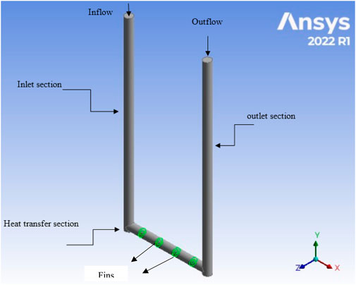
Figure 1. Layout of EAHE pipe with fins.
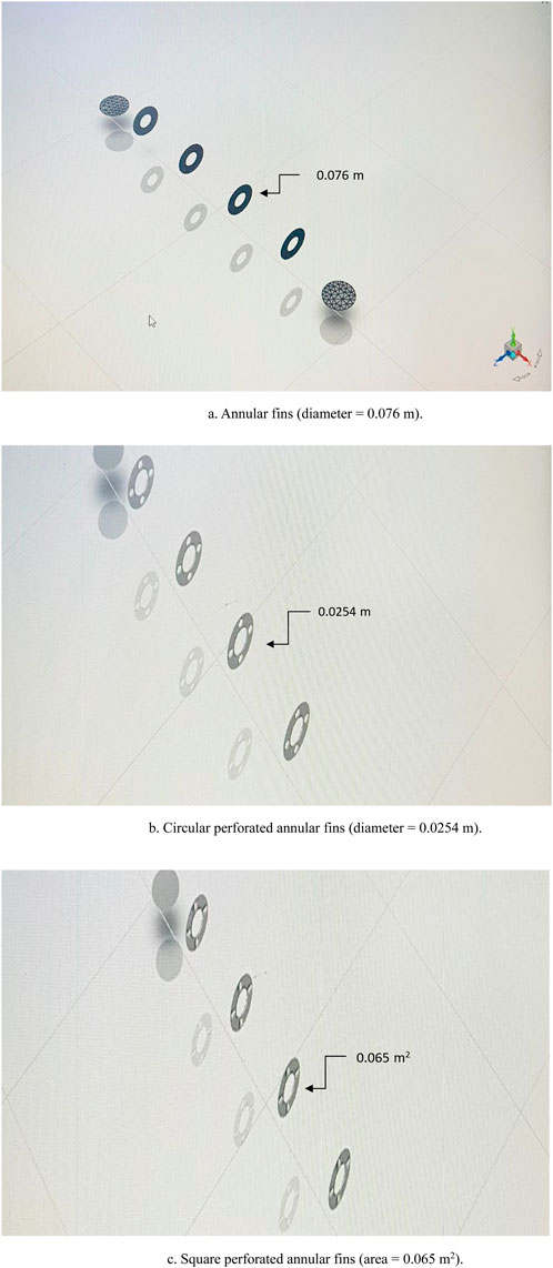
Figure 2. (a–c) Schematic diagrams of EAHE system models with different fins.
3 Experimental configuration and setup
This study employs an experimental approach, utilising the ground as a heat sink, to evaluate the performance of an EAHE with and without fins. The system was buried at a depth of 3.5 m, and two distinct designs were considered. The first configuration consisted of a 1.5 m horizontal section of 6-inch diameter tubing, along with inlet and outlet sections, without any fins. The second design was identical but included four annular fins with an internal diameter of 0.076 m. Regarding the fin specifications, Table 1 demonstrates the fin parameters used in the current research, which were carefully selected based on material properties and geometric optimisation to balance heat transfer enhancement and pressure drop.
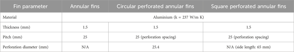
Table 1. Fin characteristics.
Figure 3 illustrates both the configurations. To support the experiment, a test room measuring 3 m wide, 6 m long, and 2.5 m high was constructed. A fan was connected to the EAHE system, as shown in Figure 4, to facilitate the airflow. Pressure gauges were installed at both the inlet and outlet to measure the pressure variations, whereas thermocouples were attached to the PVC pipe to monitor the temperature changes. In addition, a flow meter was used to measure the air velocity exiting the heat exchanger. A single thermocouple was used inside the test room to track the temperature variations, as shown in Figure 5. The experimental setup also included ten sensors buried vertically in the ground at 30 cm intervals, as illustrated in Figure 6, to measure the earth’s temperature distribution. The results showed that, below a depth of 3 m, the ground temperature remained stable at 30°C. Thermocouple readings were recorded using a data logger, and the experiments were conducted on multiple days between late July and the end of August 2023.
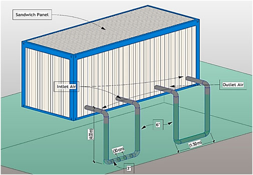
Figure 3. A schematic representation of the EAHE design with and without fins positioned inside a hole with a 0.15 m diameter.

Figure 4. The fan was connected to the ground-air heat exchanger.
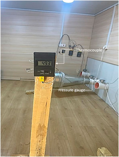
Figure 5. A single thermocouple was used to monitor the internal temperature.
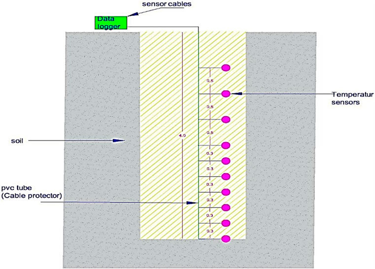
Figure 6. A schematic diagram of the thermocouple of ten sensors buried vertically in the ground to measure the earth’s temperature.
3.1 Experimental setup and equipment
The following equipment were utilised during the experiments:
• Test Room: A model constructed from a sandwich panel material is known for its excellent heat-insulating properties. The dimensions of the rooms were 6 × 3 × 2.5 m.
• PVC Pipes: These underground pipes had a horizontal section approximately 1.5 m in length and a 6-inch diameter.
• Thermocouples: K-type thermocouples were used for the temperature measurements. One thermocouple was placed at the centre of the test room, and additional thermocouples were positioned at the inlet and outlet of the PVC pipes.
• Data Logger: An electronic device with eight channels, model S220-T8, was used to record temperatures within a range of −200°C–1,800°C. The device monitored the temperature gradient in the ground.
• Flow Meter with model number MS6252A: This instrument measured the airflow speed from both the fan and the outlet of the PVC pipes.
• Pressure Gauges with model number ADT680-05-GP3K-BAR-N2: These gauges were used to measure the pressure within the EAHE at both the inlet and outlet of the ground-air heat exchanger.
To elucidate the potential sources of uncertainty and their estimated magnitudes, Table 2 provides a detailed breakdown of this information. This approach offers a comprehensive understanding of measurement variability and reinforces the reliability of the current results.
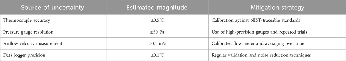
Table 2. Sources of uncertainty and associated mitigation strategies.
4 Theoretical modelling
4.1 Assumptions
A mathematical model has been developed based on the following assumptions (Mhamuad et al., 2008; Ibrahim et al., 2018; Hasan et al., 2014):
• The flow is turbulent and maintains a constant equilibrium state.
• The incoming velocity remains uniform and steady throughout the process.
• The fluid is considered incompressible with constant specific heat, density, and thermal conductivity.
• There is perfect thermal contact between the pipe and the surrounding soil.
• Heat conduction within the fin is steady over time.
• The thermal conductivity of the fin remains constant.
4.2 Governing equations
As detailed in Equations 1–5, the fundamental equations govern the flow and describe the underlying fluid behaviour. For a steady flow, the continuity equation is expressed as (Kosdere et al., 2024):
Momentum equations for the x-, y-, and z-directions:
Energy equation:
u, v and w represent the velocity components in x, y, z directions, ρ density, p pressure, ν kinematic viscosity, T temperature and α = k/ρcp thermal diffusion coefficient, respectively.
The performance parameters of the systems under investigation are evaluated using Equations 6–13. The heat transfer calculation for the air supplied to the room is conducted as follows. The airflow area of the PVC pipe supply opening (m2) can be determined using the method outlined in Gan (2015), Hasan and Jabbar (2021), Niu et al. (2015), and Hasan and Noori (2019):
D is the diameter of the PVC pipe.
ρ is the density of the air (kg/m3), and V is the velocity of the air (m/s).
The heat absorbed by the EAHE is calculated as follows:
Tin is the inlet temperature of the EAHE, and To is the outlet temperature from the EAHE.
The performance factor (COP) was used to measure the overall performance of the EAHE.
Ppwr is the pumping power, calculated as follows:
The pressure drop is estimated using the following equation:
The volumetric flow rate
To determine the flow type the following equation is used:
Dh is the hydraulic diameter.
4.3 Boundary conditions
The mathematical model was extended using the following boundary conditions:
4.3.1 Inlet boundary condition
Regardless of the presence of fins, the initial section of the EAHE pipe maintained a steady air velocity and constant dry-bulb temperature (Ti) at the inlet under turbulent and subsonic flow conditions. The selection of Ti values as boundary conditions was based on the prevailing weather conditions in Nasiriya City, located in southern Iraq, for the entire year.
4.3.2 Outlet boundary conditions
The pressure at the outlet was considered to be at atmospheric level (relative to zero), and the temperature was determined through calculations.
4.3.3 Pipe wall
The horizontal section of the EAHE pipe was in direct thermal contact with the disturbed soil, requiring the application of conjugate heat transfer as the boundary condition for this segment. Beyond the disturbed soil, at a distance (t) from the pipe wall, the temperature remained constant and corresponded to the undisturbed soil temperature (Ts = 30°C). The temperature was determined through experimental measurements conducted in southern Iraq at depths of 3–4 m. To simplify the numerical solution, both the vertical sections of the EAHE were assumed to have thermally insulating boundary conditions. This assumption was based on the presence of equal and opposite temperature gradients in the air within the inlet and outlet vertical sections.
5 Theoretical modelling
The numerical solution of the governing equations was obtained using the finite volume method and CFD modelling to solve the 3D Navier-Stokes equations along with the continuity equation.
5.1 Numerical modelling
CFD was used to analyse the airflow dynamics within the EAHE pipe, considering the specific boundary conditions. To model the turbulence inside the pipe, the k–ε turbulence model with standard wall treatment was used, and the energy equation was solved to account for heat transfer effects. CFD modelling enables the evaluation of airflow characteristics at various points within an EAHE system, which is typically represented by a numerical grid or mesh.
5.2 Grid independence test
To assess the accuracy of the simulation model, a grid independence test was conducted. The solution is considered grid-independent if the results remain stable despite the mesh refinement, which involves reducing the cell size and increasing the total number of cells. The importance of transparency in mesh specifications was acknowledged in this research. The mesh sizes for the grid independence test were carefully selected to assure accuracy. Specifically, Mesh 1 used a coarse resolution of 1.2 million elements, Mesh 2 refined to 2.5 million elements, Mesh 3 further refined to 4.0 million elements, and finally Mesh 4, the finest, at 5.8 million elements. The marginal variation in outlet temperature between Mesh 3 and Mesh 4 (less than 0.01%) can ascertain the grid independence, validating the reliability of the current simulations. This technique can ensure that the current findings are both precise and computationally efficient.
Table 3 presents the results of the grid-independence analysis. The results indicate that the change in grid size from mesh size 3 to mesh size 4 has a negligible effect on the solution for the EAHE system, both with and without fins, demonstrating either grid independence or minimal impact on air temperature.
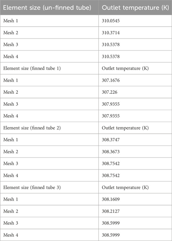
Table 3. Grid independent results.
5.3 Validation of the simulation model
To assess the reliability of the numerical model, a comparison was conducted between the numerical results and the experimental data, as illustrated in Figure 7. This figure highlights the variance between the outlet air temperature and fluctuating inlet air temperature while maintaining a constant air velocity. As shown in Figure 7, the results clearly demonstrate a strong correlation, with an average percentage error of 16% for the un-finned tube and 14% for finned tube 1, confirming an acceptable level of agreement. Figure 7 presents a comparative analysis of the annular finned and un-finned tubes from both practical and theoretical perspectives. The data indicate that the exit temperature of the un-finned tube exceeds that of the finned tube, and both exhibit a temperature decline as the inlet temperature decreases. Despite this trend, the un-finned tube consistently maintains a higher exit temperature. The theoretical findings align with practical observations, reaffirming that the fins in the annular finned tube play a critical role in reducing the air temperature as it passes through the heat exchanger. This temperature reduction was primarily attributed to the vortices generated by the fins, which induced airflow disturbances within the tube. Consequently, the air remained inside the tube for an extended period, enhancing the heat exchange efficiency between the tube and its surroundings, ultimately resulting in cooler air exiting the heat exchanger.
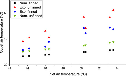
Figure 7. Comparison of outlet air temperature against inlet air temperature for un-finned and finned tubes for numerical and experimental results.
6 Results and discussion
The numerical solution of the model was performed while accounting for the distinct summer and winter climatic conditions in Nasiriya, a city in southern Iraq. The thermal and material properties of both the air and PVC pipe material were considered constant, with specific values referenced from Table 4 (Asgari et al., 2020; Rashid et al., 2023).

Table 4. Thermal and physical properties of air and pipe materials.
Figure 8 shows the relationship between the temperature difference (Ti-To) and inlet air temperature for both the annular finned and un-finned tubes, considering both experimental and theoretical perspectives. Practically, the annular finned tube exhibits a greater temperature difference than the un-finned tube, particularly at higher inlet temperatures, which influences the overall temperature variation. Similarly, the theoretical analysis indicated a higher temperature difference for the finned tube. However, in practical observations, the temperature difference for both tubes were lower than the theoretical predictions.

Figure 8. Comparison of air temperature difference against inlet air temperature for un-finned and finned tubes for numerical and experimental results.
Additionally, Figure 9 illustrates the relationship between the heat transfer rate (kW) and inlet air temperature (Ti) for both tubes in both the experimental and numerical analyses. Similar to Figure 8, the heat transfer rate depended on the temperature difference and flow rate. Because the flow rate remained constant for both tubes, the primary influencing factors were the inlet and outlet temperatures.
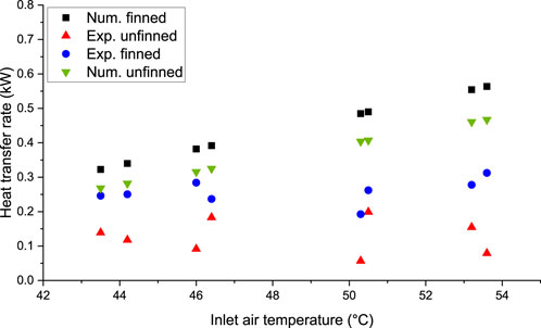
Figure 9. Comparison of heat transfer rate against inlet air temperature for un-finned and finned tubes for numerical and experimental results.
Referring to the demonstrated results of Figures 8, 9, the noted discrepancy between numerical and experimental results for the finned tubes, specifically at high inlet air temperatures, can be ascribed to a number of reasons. First of all, the numerical model has a limitation to precisely capture the complicated heat transfer dynamics at elevated inlet air temperatures. In this regard, the physical fluid properties such as the thermal conductivity, and convection coefficients can be changed at such elevated air temperatures. Also, the thermal resistance can be increased at elevated air temperatures, which might introduce a non-linear behaviour in the material properties of the fins or surrounding medium. Specifically, the utilised model cannot fully account this in the simulation. Lastly, at high inlet air temperature, there would be significant changes in local flow patterns, heat losses to the environment, besides inaccuracies in boundary conditions, which would all contribute to such observed difference.
Figure 10 illustrates the variation in the pressure drop (Pa) (Pi-Po) and inlet air temperature (Ti) for both the annular finned tube and the un-finned tube, considering both practical observations and theoretical analysis. In practical scenarios, the finned tube experienced a greater pressure drop than the un-finned tube. This was attributed to the fins disrupting the airflow within the tube, leading to irregular air movement and increased internal pressure. Consequently, the pressure inside the tube fluctuated with changes in the inlet temperature, creating an alternating curve. In addition, based on the gas law (P = mRT), the pressure and temperature are directly proportional if the volume remains constant. Similarly, theoretical analysis confirmed that the finned tube exhibited the highest pressure drop, whereas the un-finned tube maintained a consistent pressure drop, regardless of variations in the inlet temperature. Therefore, both practical observations and theoretical findings indicate that the finned tube consistently experienced a higher pressure drop than the un-finned tube.
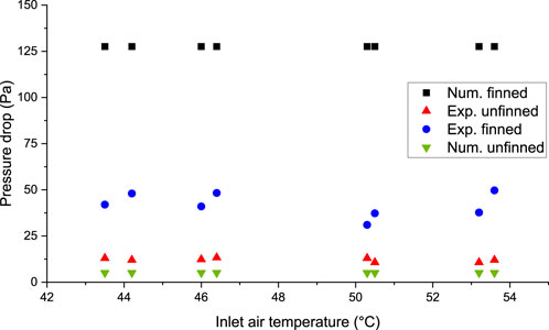
Figure 10. Comparison of pressure drop versus inlet air temperature for un-finned and finned tubes for numerical and experimental results.
Figure 11 shows the relationship between the pumping power (kW) and inlet air temperature for both the finned and un-finned tubes in both the experimental and numerical simulations. This figure closely resembles that shown in Figure 10, as the pumping power is influenced by factors such as the pressure drop, air velocity, and tube surface area. Because the air velocity and tube area remained constant for both configurations, the only variable affecting the pumping power was the pressure drop. Consequently, the finned tube exhibited a higher pumping power than the un-finned tube in both settings.
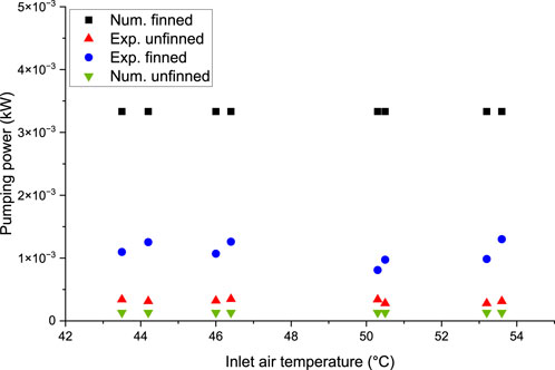
Figure 11. Comparison of pumping power versus inlet air temperature for un-finned and finned tubes for numerical and experimental results.
Figure 12 illustrates the correlation between the performance factor and the inlet air temperature for both the annular finned and un-finned tubes. Based on the experimental results, the un-finned tube demonstrates a higher performance factor than the annular finned tube. This can be attributed to lower heat transfer rates and reduced pumping power requirements. Notably, the performance factors observed in the experimental settings for both tubes as well as the theoretical performance factor of the non-finned tube were the highest. This is primarily due to the un-finned tube’s reliance on minimal heat transfer rates and pumping power, depending on whether the system prioritizes the heat transfer efficiency or pressure drop.
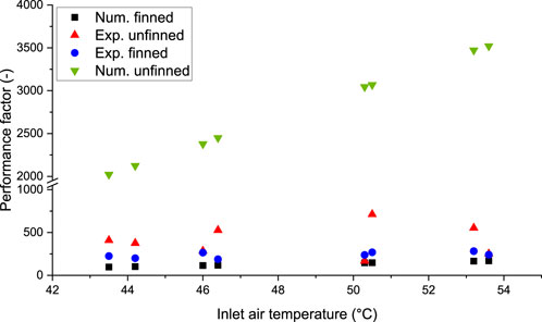
Figure 12. Comparison of performance factor versus inlet air temperature for un-finned and finned tubes for numerical and experimental results.
Figure 13 shows the relationship between the variations in the inlet temperature and its effect on the outlet temperature for un-finned tubes, annular finned tubes, circularly perforated annular tubes, and square-perforated annular tubes. The figure indicates that all curves follow a similar trend, with the outlet temperature decreasing as the inlet temperature decreases. However, the un-finned tube consistently exhibited higher outlet temperatures than the other configurations. Notably, the finned tubes in both perforated designs exhibited the lowest outlet temperatures. This behaviour can be attributed to the turbulence generated in the perforated sections, which prolonged the residence time of the air within the tube. As a result, this extended interaction enhances the heat exchange between the air inside the tube and the surrounding environment.
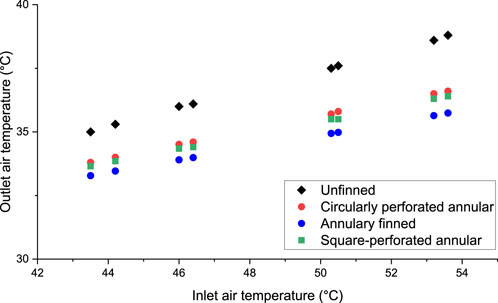
Figure 13. Comparison of outlet air temperature versus inlet air temperature for EAHE system with and without fins.
Figure 14 illustrates the relationship between the air temperature difference and inlet air temperature for the un-finned tubes, annular finned tubes, circularly perforated annular tubes, and square-perforated annular tubes. The figure shows that as the inlet air temperature decreased, the temperature difference also decreased. However, the non-finned tube consistently exhibited a lower temperature difference than the other configurations. This is because of its higher outlet temperature, which results in limited heat exchange between the tube and the surrounding soil. Consequently, the outlet temperature declined at a slower rate because there was insufficient time for significant cooling. In contrast, the finned tubes in both configurations exhibited a greater temperature difference, with all finned-tube curves displaying nearly identical values.
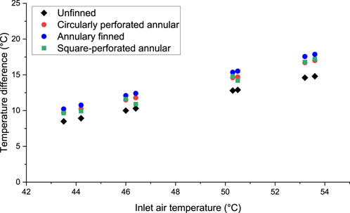
Figure 14. Comparison of air temperature difference versus inlet air temperature for EAHE system with and without fins.
Figure 15 illustrates the relationship between the inlet temperature and heat transfer rate (kW) for the un-finned tubes, annular finned tubes, circularly perforated annular tubes, and square-perforated annular tubes. The figure shows that the heat-transfer rate decreased as the inlet temperature decreased. However, the un-finned tube consistently exhibited a lower heat transfer rate than the other configurations. This is because of its higher inlet temperature and smaller temperature difference, which limits the heat exchange between the tube and the surrounding soil. Notably, the finned tubes in the first configuration achieved higher heat transfer rates than both the un-finned tube and other finned configurations.
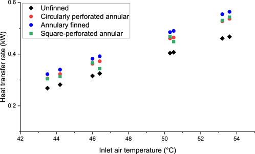
Figure 15. Comparison of heat transfer rate against inlet air temperature for EAHE systems with and without fins.
Figure 16 shows the relationship between the pressure drop and inlet air temperature across various tube configurations, including un-finned, annular-shaped finned, and annular-perforated tubes with both circular and square perforations. The figure demonstrates a consistent trend, with an approximately constant pressure across the studied configurations. Among these, annular finned tubes exhibit the highest pressure drop owing to swirling effects within the perforated regions, which generate air turbulence, disrupt airflow, and increase internal pressure. Additionally, annular-finned tubes with square perforations experience a greater pressure drop than those with circular perforations. In contrast, the un-finned tubes had the lowest pressure drop because their linear airflow remained undisturbed by turbulence. Notably, despite variations in the air temperature, the pressure drop in the un-finned tubes remained constant.
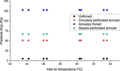
Figure 16. Comparison of pressure drop against inlet air temperature for EAHE system with and without fins.
Figure 17 illustrates the relationship between pumping power and inlet air temperature for various tube configurations, including un-finned tubes, annular-shaped finned tubes, and annular-perforated tubes with circular and square perforations. The pumping power remained relatively stable for each configuration owing to the consistent pressure drop. Among the studied configurations, annular finned tubes exhibited the highest pumping power, primarily owing to swirling effects in the perforated regions, which create air turbulence and increase the pressure drop. Additionally, annular-finned tubes with square perforations require more pumping power than those with circular perforations. Conversely, un-finned tubes have the lowest pumping power because their linear airflow results in a minimal pressure drop. Despite the decrease in air temperature, the pressure drop remained unchanged, ensuring that the pumping power remained constant throughout the temperature variation.
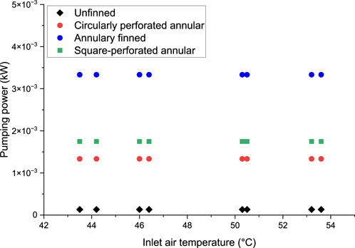
Figure 17. Comparison of pumping power versus inlet air temperature for EAHE systems with and without fins.
Figure 18 illustrates the relationship between the performance factor and inlet air temperature for various tube configurations including un-finned tubes, annular-shaped finned tubes, and annular-perforated tubes with circular and square perforations. Among these, the un-finned tube demonstrates the highest performance factor, primarily because of its lower pumping power, which reduces energy consumption and improves overall system efficiency. However, as the inlet air temperature decreases, the performance factor gradually decreases. This merit is specifically distinct at higher inlet air temperatures, where the un-finned design can preserve operational efficiency with reduced energy input.
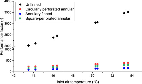
Figure 18. Comparison of performance factor versus inlet air temperature for EAHE systems with and without fins.
In contrast, finned tubes, including both annular and perforated configurations, regardless of the perforation shape, exhibit the lowest and relatively stable performance factors. This is attributed to their higher pumping power necessitated to overcome the additional friction and pressure losses linked to the fins and perforations. In turn, this has resulted in consistently lower efficiency. The performance factor for the un-finned tube depicts a gradual decline as a result to decreasing the inlet air temperature. This result would suggest that while the finned tubes remain efficient, they still sensitive to changes in inlet air temperature, probable reflecting increased thermal resistance. Among the finned tube configurations, the annular finned tube had the lowest performance factor. This is an indication of a trade-off in terms of energy efficiency despite the existence of fins can enhance the heat transfer rate. This can signify the necessity of optimising the fin configuration to assure a satisfied balance between heat transfer performance and pumping power. On top of this, these results demonstrate the request of careful selection of tube design based on specific operational requirements and inlet air temperature to attain optimal performance in air-to-ground heat exchanger systems.
7 Conclusion
In this research, a compact geothermal air-exchanger prototype was developed for use as a cooling system in both numerical simulations and practical experiments. Testing was conducted at the Thi-Qar Oil Company in southern Iraq, yielding the following results:
• The heat transfer rate was more effective in the annular finned tube than in the un-finned tube at various inlet temperatures.
• The pressure drop in the annular finned tube exceeded that in the un-finned tube at different inlet temperatures.
• Regarding the performance factor, the finned tube exhibited lower values than those of the un-finned tube.
• A comparison between the non-finned tube and finned tubes with various fin shapes in the theoretical simulations revealed that the annular finned tube had the lowest exit temperature. Thus, the cooling efficiency of the annular finned tube surpassed those of the other fin shapes. Additionally, the heat transfer rates of all finned tube shapes were higher than that of the un-finned tube.
• The pressure drop in the finned tubes was greater than that in the non-finned tubes. Specifically, the highest pressure drop was observed in the annular finned tube, followed by the annular finned tube with square perforations, and finally the annular finned tube with circular perforations.
Referring to these conclusions, it can be said that adding fins to the heat exchanger can enhance heat transfer rates. In this regard, the annular finned tube elaborated superior cooling efficiency in a comparison to un-finned tubes. This can be attributed to increased surface area with the existence of fins available for heat exchange, which can contribute to reduce the thermal resistance. However, this would exhibit a higher pressure drop, which was justified by improving the heat transfer performance.
Data availability statement
The raw data supporting the conclusions of this article will be made available by the authors, without undue reservation.
Author contributions
EH: Writing – review and editing, Writing – original draft, Software, Validation, Conceptualization, Visualization, Methodology, Formal Analysis. MH: Software, Writing – original draft, Validation, Conceptualization, Visualization, Formal Analysis, Methodology. FR: Formal Analysis, Software, Writing – original draft, Methodology, Visualization, Conceptualization, Validation. MA: Conceptualization, Validation, Writing – original draft, Formal Analysis, Software, Visualization, Methodology. AA: Writing – review and editing, Visualization, Formal Analysis, Project administration, Methodology.
Funding
The author(s) declare that no financial support was received for the research and/or publication of this article.
Conflict of interest
The authors declare that the research was conducted in the absence of any commercial or financial relationships that could be construed as a potential conflict of interest.
Generative AI statement
The author(s) declare that no Generative AI was used in the creation of this manuscript.
Publisher’s note
All claims expressed in this article are solely those of the authors and do not necessarily represent those of their affiliated organizations, or those of the publisher, the editors and the reviewers. Any product that may be evaluated in this article, or claim that may be made by its manufacturer, is not guaranteed or endorsed by the publisher.
Abbreviations
References
Alavi, S. E., and Shirbani, M. M. (2024). Thermo-hydraulic analysis and optimization of finned tube heat exchangers. Multiscale Multidiscip. Model. Exp. Des. 7, 2031–2043. doi:10.1007/s41939-023-00320-3
Al-Obaidi, M. A., Rashid, F. L., Rasheed, M. K., Aljibori, H. S. S., Mohammed, H. I., Mahdi, A. J., et al. (2024). Recent achievements in heat transfer enhancement with hybrid nanofluid in heat exchangers: a comprehensive review. Int. J. Thermophys. 45, 133. doi:10.1007/s10765-024-03428-x
Al Takash, A., Faraj, J., Awad, S., El Hage, H., and Khaled, M. (2025). Heating water using the hot air of condensers and tubes-and-fins heat exchangers – thermodynamic modeling and parametric study with economic and environmental insights. Unconv. Resour. 6, 100146. doi:10.1016/J.UNCRES.2025.100146
Asgari, B., Habibi, M., and Hakkaki-Fard, A. (2020). Assessment and comparison of different arrangements of horizontal ground heat exchangers for high energy required applications. Appl. Therm. Eng. 167, 114770. doi:10.1016/J.APPLTHERMALENG.2019.114770
Basavarajappa, S., Manavendra, G., and Prakash, S. B. (2020). A review on performance study of finned tube heat exchanger. J. Phys. Conf. Ser. 1473, 012030. doi:10.1088/1742-6596/1473/1/012030
El-Sebaey, M. S., El-Din, S. S., and El-Kholy, M. K. (2024). Heat transfer and fluid flow performance of an internally longitudinal finned tube: numerical study and experimental validation. Int. J. Therm. Sci. 201, 109025. doi:10.1016/J.IJTHERMALSCI.2024.109025
Gan, G. (2015). Simulation of dynamic interactions of the earth–air heat exchanger with soil and atmosphere for preheating of ventilation air. Appl. Energy 158, 118–132. doi:10.1016/J.APENERGY.2015.08.081
Hasan, M. I., Hasan, H. M., and Abid, G. A. (2014). Study of the axial heat conduction in parallel flow microchannel heat exchanger. J. King Saud Univ. Eng. Sci. 26, 122–131. doi:10.1016/J.JKSUES.2012.12.004
Hasan, M. I., and Jabbar, E. K. (2021). Fabricating and testing of the ground coupled air conditioner for residential applications in Iraqi weather. Energy 216, 119256. doi:10.1016/J.ENERGY.2020.119256
Hasan, M. I., and Noori, S. W. (2019). A study of the potential of using the Earth to air heat exchanger for cooling and heating of residential buildings in Iraq. Heat Transfer Asian Res. 48, 3902–3927. doi:10.1002/htj.21574
Ibrahim, T. K., Mohammed, M. N., Mohammed, M. K., Najafi, G., Azwadi Che Sidik, N., Basrawi, F., et al. (2018). Experimental study on the effect of perforations shapes on vertical heated fins performance under forced convection heat transfer. Int. J. Heat. Mass Transf. 118, 832–846. doi:10.1016/J.IJHEATMASSTRANSFER.2017.11.047
Kosdere, O., Sert, Z., and Altun, O. (2024). Investigation of thermal performance at forced convection in plate-fin heat sink. Energy 307, 132621. doi:10.1016/J.ENERGY.2024.132621
Liu, L., Fan, Y., Ling, X., and Peng, H. (2013). Flow and heat transfer characteristics of finned tube with internal and external fins in air cooler for waste heat recovery of gas-fired boiler system. Chem. Eng. Process. Process Intensif. 74, 142–152. doi:10.1016/J.CEP.2013.09.003
Mhamuad, A. M., Ibrahim, T. K., and Jasim, R. R. (2008). Determination of the temperature distribution the perforated fins under natural convection. Tikrit J. Eng. Sci. 15, 63–78. doi:10.25130/tjes.15.2.05
Niu, F., Yu, Y., Yu, D., and Li, H. (2015). Heat and mass transfer performance analysis and cooling capacity prediction of earth to air heat exchanger. Appl. Energy 137, 211–221. doi:10.1016/J.APENERGY.2014.10.008
Olczak, P., Porzuczek, J., and Olek, M. (2025). Investigation on the efficiency of evacuated tube collector with heat pipe in different configurations of internal fin mounting. Sol. Energy Mater. Sol. Cells 282, 113391. doi:10.1016/J.SOLMAT.2024.113391
Pai, Y. W., and Yeh, R. H. (2022). Experimental investigation of heat transfer and pressure drop characteristics of internal finned tubes. Int. J. Heat Mass Transf. 183, 122183. doi:10.1016/J.IJHEATMASSTRANSFER.2021.122183
Rashid, F. L., Dhaidan, N. S., Hussein, A. K., Al-Mousawi, F. N., and Younis, O. (2023). Ground heat exchanger in different configuration: review of recent advances and development. Geoenergy Sci. Eng. 227, 211872. doi:10.1016/J.GEOEN.2023.211872
Shabgard, H., Allen, M. J., Sharifi, N., Benn, S. P., Faghri, A., and Bergman, T. L. (2015). Heat pipe heat exchangers and heat sinks: opportunities, challenges, applications, analysis, and state of the art. Int. J. Heat Mass Transf. 89, 138–158. doi:10.1016/J.IJHEATMASSTRANSFER.2015.05.020
Skheel, O. R., Yasin, N. J., Al-abbas, A. H., and Soomro, S. A. (2023). Experimental study of the wickless heat pipe heat exchanger by using Nano fluid. J. Tech. 5, 115–130. doi:10.51173/jt.v5i4.1278
Keywords: heat exchanger, finned tubes, air compression cooling, energy efficiency, numerical and experimental study
Citation: Hummood EA, Hasan MI, Rashid FL, Al-Obaidi MA and Ameen A (2025) Performance analysis of air-to-ground heat exchanger systems: a detailed investigation of finned and un-finned tube designs for oil pipeline cooling. Front. Energy Effic. 3:1612724. doi: 10.3389/fenef.2025.1612724
Received: 16 April 2025; Accepted: 22 May 2025;
Published: 30 May 2025.
Edited by:
Zhiming Gao, Oak Ridge National Laboratory (DOE), United StatesReviewed by:
Pengtao Wang, Oak Ridge National Laboratory (DOE), United StatesChengyun Xin, China University of Mining and Technology, China
Copyright © 2025 Hummood, Hasan, Rashid, Al-Obaidi and Ameen. This is an open-access article distributed under the terms of the Creative Commons Attribution License (CC BY). The use, distribution or reproduction in other forums is permitted, provided the original author(s) and the copyright owner(s) are credited and that the original publication in this journal is cited, in accordance with accepted academic practice. No use, distribution or reproduction is permitted which does not comply with these terms.
*Correspondence: Arman Ameen, YXJtYW4uYW1lZW5AaGlnLnNl