- 1School of Engineering and Applied Sciences, Ahmedabad University, Ahmedabad, India
- 2Department of Chemical Engineering, Institute of Chemical Technology, Mumbai, India
Solar power has gained particular importance in the current era due to a need of harnessing the biggest and cleanest source of energy, i. e., solar energy. One of the most innovative as well as simple technique to generate solar power is using a solar chimney. Solar chimney power plant, however, requires high investment costs and traditionally have been of very low efficiency. Mathematical and CFD models pose a good way to optimize performance of such kind of chimneys. Several factors affect the power generation from a solar chimney including geometric factors (like collector diameter, chimney height) and diurnal temperature variations. The challenge however lies in diurnal variation of temperatures and hence unstable power generation. In the present work, a pilot scale CFD model of solar chimney (of prototype of Manzanares Chimney, Spain, Haaf, 1984) was built and validated with experimental data and analytical models from the literature (~ <10% deviation from experimental data). Subsequently, flow patterns were studied and a parametric study was carried out for the chimney for the key parameters, namely, chimney height, and collector diameter. For the first time effect of diurnal variations on the power generated was studied. With consideration of diurnal variations, power generation during night was found to be a linear function of chimney height and collector diameter; while, during day time, the power-generated increased exponentially with variation in collector diameter and chimney height.
Introduction
Energy is one of the most important needs for the mankind. With conventional energy sources steadily depleting, economic and environmentally safe sustainable energy source needs to be found. The main sources of energy have been tabulated in Table 1. Clean energy in terms of electricity can be generated by using renewable sources like solar, biomass, wind etc. Solar energy is one of the untapped energy sources in countries (South East Asian countries like India, European countries like Spain, African countries etc.), which have enough amount of sunlight throughout the year and enough land to receive sunlight. India has been harnessing solar power extensively in the recent years. Many devices to harness the power of solar energy, such as, photovoltaic cells, concentrated troughs etc., have been used to tap the solar energy. Implementation of these devices, however, demands large amounts of land to be occupied. This means the land would be particularly barren land. A viable option is in which energy can be utilized along with cultivation occurring on the land. Such an objective can be to certain extend can be fulfilled by harnessing the concept of a solar chimney.
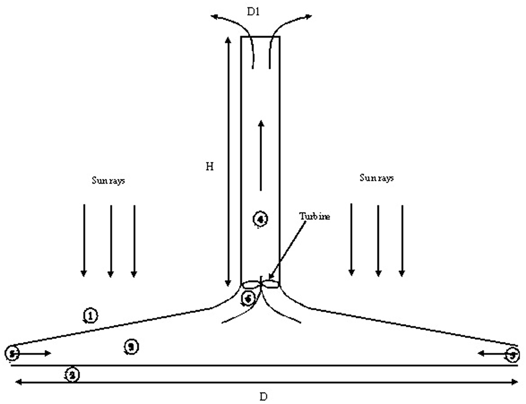
Schematic of a typical solar chimney is shown in Figure 1. Solar Chimney Power Plant works on the principle of natural convection based on the temperature gradient in the atmosphere and the chimney top. Also at the bottom of the chimney, solar collector absorbs solar radiations and stores the heat on natural ground. The radiation from the sun falls on the transparent cover (1). The cover is inclined and forms a cover on the natural ground (2) The air enclosed in the space (3) between (1) and (2) heats up with time. At the center of the cover lies a vertical cylindrical chimney (4) of height H and diameter D1. As temperature of the air enclosed in (3) increases, density difference between the air outside the cover (ambient air) also increases and the air enclosed in (3) and cold air gets sucked through (5). Hot air moves upward through the chimney causing an up-draft. While moving, air rotates the turbine (6) placed at the joint between the cover (2) and chimney (4). Turbine generates electricity by converting mechanical energy into electrical energy.
Due to large capital involved in building the solar chimney, experimental pilot set ups have limited scope. On the other hand, advanced CFD simulations can be proved to be better tool to optimize the performance of the existing solar chimneys as well as designing improved configurations. Moreover, with cost of computation coming down and computation power going up, advanced CFD simulations can be used for detailed studies. Nonetheless, experimental validation of these simulations are essential to ensure that required physics is captured in the model. This has been our motivation for the present work.
The present paper is described as follows: Section Literature Review covers the literature overview which includes experimental as well as theoretical attempts in this field. The objective of the present work is summarized in section Objective of Present Work in order to extend limitations from the previous models. Sections Mathematical modeling and Model Equations of Theoretical Models From Literature cover governing equations used for the CFD simulations. Results are illustrated in section Results and Discussion which incorporate, model validations as well as sensitivity studies for Indian conditions. Finally, we conclude the findings in section Conclusions.
Literature Review
Researchers over the last many years have worked on analysis of solar chimney for an effective source of power generation. Significant work has been done during the past 3 decades on the effectivity of solar chimney as a power generation source. We present only a few of them here in the context and alignment of the present work. Table 2 presents some of the prominent experimental, analytical and CFD works. Research work has been done using experimental methods (Haaf, 1984; Zhou et al., 2007; Shahreza and Imani, 2015), analytical models (Padki and Sherif, 1989a,b, 1999; Pasumarthi and Sherif, 1998a,b; Bernardes et al., 2003; Dai et al., 2003; Pretorius and Kroger, 2006; Tingzhen et al., 2006; Koonsrisuk and Chitsomboon, 2009; Panse et al., 2011) and Computational Fluid dynamics (CFD) analysis (Ming et al., 2008; Fasel et al., 2012; Filkoski et al., 2013; Gholamalizadeh and Kim, 2014; Hassan et al., 2018).
The experimental work majorly refers to the solar chimney power plant in the Manzanares desert in Spain (capacity to generate power of 50 kW), which was built as a joint effort between German ministry and a Spanish utility company. Schlaich (1995) described the concept of solar chimney power plant. (Haaf, 1984) discussed the principle and construction of the power plant. Haaf (1984) also reported the design criteria and cost analysis of the Manzanares plant as well as experimental data of preliminary test results. Another important experimental work on a pilot plant was conducted by Zhou et al. (2007). Though the pilot plant was much smaller in size (capacity to generate power of 5W), objective was to study the temperature field across the entire plant. The authors tried to find the diurnal variation of temperature across the solar collector. Their experiments could provide key data on following two parameters: 1. Maximum temperature difference in the center of the solar collector and the air outside the solar collector. 2. Criteria for obtaining a steady power generation based on identification of a span in a day when steady air flow can be obtained (without any temperature inversion). Recently, Shahreza and Imani (2015) performed experimental and numerical simulations on a small scale model of solar chimney (Diameter of chimney = 16 cm and height = 150 cm while collector diameter = 92 cm. Authors used intensifiers to intensify the heat radiated from the sun. They also used air tanks to absorb the heat radiation reflected by the intensifiers to store the heat from radiations. Authors claimed to have obtained velocities of the order of 5.12 m/s. Further, the authors performed CFD simulations for this experimental model and found good agreement with experimental results.
Padki and Sherif (1989a,b) developed one dimensional models to find thermodynamic aspects of solar chimney power plants. They also presented a mathematical model and validated the model with experimental results of Manzanares plant. Chitsomboon (2001) presented an analytical model for frictionless one dimensional flow using conservation equations of mass and energy integrated with ideal gas relations. Author also developed a two dimensional CFD code using implicit finite volume methodology. The results of analytical model and CFD model were compared for power predictions (both qualitative and quantitative) and good agreement was observed. The analytical model of Chitsomboon (2001) determined both flow and temperature at different parts of the solar power plant. Dai et al. (2003) performed a simple energy balance to find the efficiency of the solar collector as well as the overall efficiency of the solar chimney. They used the model to predict effect of parameters, like, solar irradiance, chimney height and collector diameter on power generation. They also carried out study on the yearly variation of power for three different regions in the northwestern region of China. Koonsrisuk and Chitsomboon (2013) developed an iterative mathematical model to predict the temperatures and pressures at different points across key points in the solar chimney. Model was used by the authors to predict pressure ratio (ratio of pressure drop between inlet and outlet of air from the chimney to the pressure drop at the turbine). Model was validated with the experimental results of Manzanares prototype Spain and sensitivity studies was performed using this model for power output as a function of mass flow rate variation, pressure ratio variation, for different heights, irradiances and collector diameters. Authors found that for the system with a constant driving pressure, optimum pressure ratio was 2/3, while for a non-constant driving force, the pressure ratio is a function of plant size and solar heat flux. Hence, they claimed that their model can suggest an appropriate plant size for serving electricity to each village, which would be feasible for the local government.
Several authors have performed CFD studies for solar chimney power plants mostly for the geometrical dimensions of Manzanares power plant and validated their model with experimental data of the plant. Ming et al. (2008) performed CFD simulations to understand flow and heat transfer across the solar chimney. Authors, however, considered ground as an energy storage layer. They presented conjugate numerical simulations of the energy storage layer, collector and chimney. They used the standard k-ε model for solving turbulence equations. Main focus of the study was on importance of energy storage layer in predicting the overall prediction of temperature distribution and performance of the plant. Sangi et al. (2011) also performed CFD simulations with energy storage layer and validated with plant data of Manzaranes plant. They tried to predict temperature pressure and velocity distributions with their models. Fasel et al. (2012) carried out CFD simulations to study the effect of distance of the collector from the ground on power input. They carried out extensive simulation work to understand the effect of scale (with reference to Manzanares pilot plant) on temperature distributions between ground and temperature cover, on the collector near to the chimney and on the ground. The scales ranged from scaling down 250 times the Manzanares plant to scaling up 5 times the Manzanares plant. They found that power varied very differently in case of smaller and larger scales and hence an optimum height for optimum power generated could not be obtained. They used 2D axisymmetric simulations using unsteady Reynolds Averaged Navier-Stokes Equations (RANS) to solve the turbulence. They also compared three different turbulence models like k-ε, k-ω, and RANS and found that RANS gave the best predictions. Deviations in the prediction of power output were attributed to the fluid dynamics in between the collector and ground. Filkoski et al. (2013) performed 3D CFD simulations for a solar chimney of collector radius of 100 m and height of 100 m, with the chimney radius increasing along its height the base being 6.25 to 10.5 m. The realizable k-ε model was chosen for turbulence formulation, while discrete ordinates (DO) model was considered for accounting for thermal radiations. Authors showed predictions of velocity and temperature patterns and recommended CFD as a powerful tool for analysis of solar chimney studies. They also stressed on a need to include heat accumulation methods, like, water pipes, water bags etc., on the ground so that considerable heat can be stored in the ground to enhance the temperature gradients at night. Authors, however, did not study the effect of diurnal variations on power generated. Gholamalizadeh and Kim (2014) performed CFD simulations for the Manzaranes prototype using the realizable k-ε model for turbulence parameters and DO model for radiation heat transfer. They captured the temperature profile of the ground, thermal efficiency of the collector and power generated and validated their model with experimental results of Manzaranes prototype. They also performed detailed analysis of the green-house effect causing depth of heat penetration in the ground and increase in mean ground temperature. This increase in mean ground temperature influenced the predicted heat storage of the ground. Authors were able to provide better predictions for temperature distributions than previous researchers and could also match the Manzanares experimental data very well. Hassan et al. (2018) performed 3D CFD simulations with energy storage layer of the ground. Authors varied the chimney diverging angle from 1 to 3° and collector slope 4 to 10°. They found that the diverging angle of 1° raises the velocity from 9.1 m/s to a remarkable value of 11.6 m/s, which is good for improving the performance of the chimney.
Objective of Present Work
The review of the current literature has shown that there are only a few experimental works for raw data. Most researchers have built analytical models and tried to validate their models with the help of the available experimental data. Further, the most used experimental data is the one of Haaf (1984) to validate the models. Several analytical and CFD studies have been also undertaken, the major focus however being the effect of the geometric parameters (like the angle of the slope of collector, diverging angle of the chimney from base to top, the height of the chimney and diameter of the collector) on the performance of the chimney. Some numerical studies have been performed on the energy storage methodologies to simulate ground as an energy storage and excellent results have been obtained. There has been considerable focus on understanding the temperature distribution from the ground to the collector which is extremely important. However, once the model is robust, there seems to be a need for doing sensitivity of variation of power to cover the diurnal variations. This is a challenging task since the ground temperature, the temperature distribution across the collector, the mean velocities at the chimney inlet, the temperature difference between ground and the collector, radiation intensity all are interconnected. Further, no CFD studies have been carried out for understanding the effect of diurnal variations on the power generated.
We present a Computational Fluid Dynamics (CFD) model to study the potential of Solar Chimney as a provider of clean energy source. The CFD model is validated with the experimental data of Haaf (1984), theoretical models of Dai et al. (2003) and Panse et al. (2011). The present work illustrates a comprehensive approach to carry out simulations for understanding the effect of geometric parameters as well as diurnal variations on the power generated. The major contributions are as follows:
1. The study of diurnal variations provides the entire research fraternity with having an insight on further studies to be carried out on how to operate the plant during the entire day/month/year for having a sustained power supply to the power grid.
2. An effort has been made to simulate full scale geometry, with optimized grid, not compromising on the near wall mesh and turbulence model selection.
3. The CFD model has been validated with experimental data as well as with analytical models before carrying out the sensitivity study. The present work provides us with a robust model which can be used to further optimize the chimney geometry for (a) effect of energy storage on power generated diurnally, (b) monthly/yearly variations by carrying out rigorous simulations with different temperature boundary conditions, (c) understanding the physics of flow and structures during the operation of the plant at steady and unsteady state conditions.
Mathematical Modeling
In this section, we describe the methodology used for the CFD simulations including assumptions considered, governing equations solved, turbulence model selected and convergence criteria set. The grid sensitivity study is also exemplified in this section.
Assumptions
1. The temperature of heat absorption layer (earth surface) is equal to the average air temperature in the solar collector.
2. The air temperature increases along the flow direction (toward the center radially inward).
3. Air follows the ideal gas law.
4. The properties of air like density, specific heat are constant for the temperature difference considered in this work.
5. Ground is at a certain temperature T1 and ambient temperature T2.
Governing Equations, Turbulence Models, and Boundary Conditions
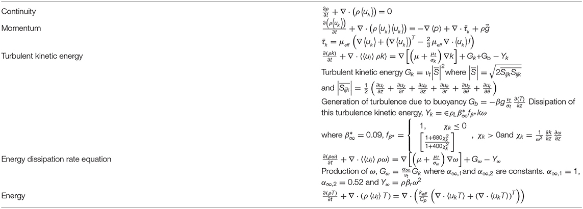
The governing equations used for the computational domain are given in Table 3. Boundary conditions are as follows: The inlet was kept as pressure inlet with ambient temperature conditions. The walls of the collector were given radiation conditions using the Rosseland model. The other parameters were listed in Table 3. The outflow boundary condition was given for the outlet of the chimney. The vertical chimney walls were kept at ambient wall temperatures. The ground was assumed to be constant temperature boundary condition.
Grid Sensitivity
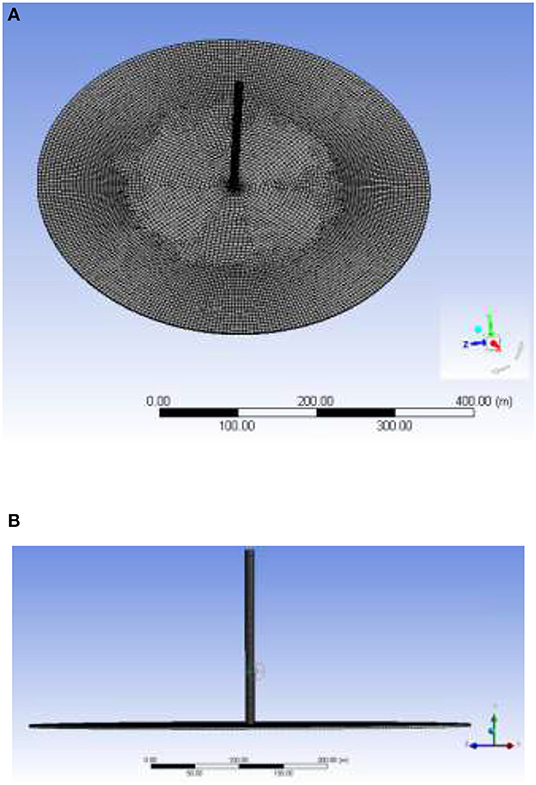
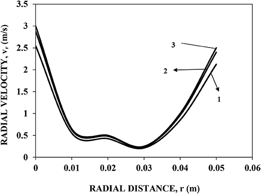
In the present work, the cylindrical chimney geometry was considered, and full scale geometry was used for grid generation. The hexahedral mesh was generated for the entire geometry with fine mesh near the walls. We managed to keep the cells to a lower value to improve the computational time to perform number of simulations. Therefore, the total computational time was reduced. Top and front view of the 3D mesh is depicted in Figures 2A,B. Grid independence was investigated by considering three different grid cases: (a) 710,000, (b) 750,000, and (c) 850,000 as shown in Figure 3. A non-uniform hexahedral grid was used with a finer grid near the duct (where turbine is placed) where high velocity gradients were more important as compared to other zones. Approximately 60% of the nodes were located in this region, and 40% were located in the rest of the region where (according to the experimental results) the fluid was essentially quiescent and the temperature varied linearly along the length i.e., radius of the collector circle. The Y+ near the walls were kept <30 so that any effect of turbulence near wall could be captured.
For these three cases, we compared the results of mean quantities at different positions. All the chosen grids predicted mean flow patterns effectively, but for further simulations a grid size of 750,000 cells were used. Minor differences were observed between 750,000 and 850,000. However, these were found to be within the (5% average error).
Method of Solution
The continuity, momentum, energy, and turbulence equations described in Table 3 (specify equation no.) were solved using commercial flow simulation software ANSYS FLUENT 171. The SST k-ω turbulence model was used for the turbulence associated with the flow. The convergence criteria for sum of normalized residues was set to 1 × 10⁻⁴ for continuity as well as for momentum, 1 × 10⁻⁶ for energy equations, while 1 × 10⁻⁵ for turbulence equations. The under-relaxation parameters were set to 0.3 for pressure, 1 each for density, energy and body forces, 0.7 for momentum equations, 0.8 for turbulence equations and 0.7 for energy equations. In this study, a segregated solver was employed for obtaining the solution of momentum equations. The momentum, energy and turbulence equations were discretized using the Second-Order Upwind Scheme (SOUS) and for pressure equation, PRESTO scheme was used. Note that SOUS scheme in the commercial software Ansys FLUENT 171 prevents numerical diffusion while taking care of the fact that it does not dampen the disturbances which cause the instability. Thus, this scheme ensured spatial accuracy in the simulations.
Turbulence Model Selection
The turbulence equations were solved using the SST k-ω model. The present problem under consideration has adverse pressure gradients at the node where there is an updraft of air. Due to adverse pressure gradients, the resolution at the near wall and the selection of turbulence model would be crucial for the energy dissipation predictions. Further, flow separation occurs since there is sudden expansion and recirculation is seen at the central portion. RNG k-ε has been used widely in literature for turbulence. Though RNG k-ε model is good for separated flows the near wall predictions for adverse pressure gradients needs attention in the problem at hand. We performed a study for comparing the performance of the two turbulence models for radial distribution of centerline velocities (As shown in Figure 4C to see centerline position). Figure 4A shows the variation of radial velocity for both turbulence models. A zoomed version of the near wall velocity is shown in Figure 4B. Clearly, there is slight deviation (~2–3%) between velocities predicted by RNG k-ε and SST k-ω models.
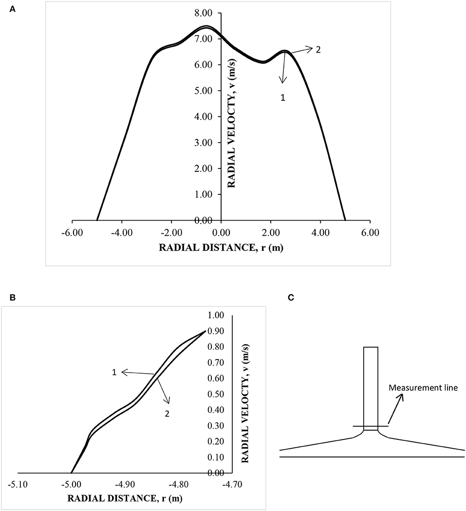
Figure 4. Comparison of velocity for selection of turbulence model (A) Velocity profiles over the measurement line, (B) Near wall velocity profiles, and (C) Position of line selected for velocity profile (1) SST k-ω model (2) RNG k-ε model.
Model Equations of Theoretical Models from Literature
Theoretical Model of Dai et al. (2003)
The Equations 1 to 5 have been reproduced from Dai et al. (2003). The efficiency of solar collector was calculated using the formulation of Dai et al. (2003):
The mechanical power taken up by the turbine is given by
The electrical energy is given by
The total power contained in the flow is given by
Temperature difference is the one between ground and the collector.
Theoretical Model of Panse et al. (2011)
Panse et al. (2011) have considered the equation of complete energy balance to find the kinetic power of the emerging air draft. The energy balance given by them is given by:
Amount of solar energy absorbed = Change in enthalpy of air + Heat losses to the surroundings + Frictional energy loss + change in pressure energy + change in potential energy + change in kinetic energy.
Since the solar chimney is inclined, the area of the solar collector considered by Panse et al. (2011) has been mapped as per Manzanares collector area. The collector area of Panse et al. (2011) is 50,000 m2, whereas collector area of Manzanares is 45,216 m2. Further, the overall deviation of Panse et al. (2011) from that of experimental data of Manzanares was around 5% (under-prediction) (Figure 5) based on power output (P = 47.5 kW as compared to 50 kW as per experimental data).
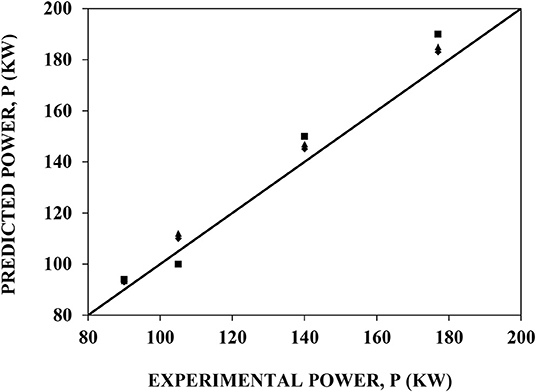
Figure 5. Parity plot of predicted power with experimental power. ■ CFD ▴ Theoretical model by Dai et al. (2003) ♦ Theoretical model by Panse et al. (2011).
Results and Discussion
In this section, the results of the CFD predictions are presented. The CFD model was first validated with the experimental results of Haaf (1984) as well as was compared with findings of the theoretical models (Dai et al., 2003 and Panse et al., 2011). The predictions were further illustrated in the form of Flow patterns (velocity and temperature contours) of the solar chimney. For prediction of temperature and flow patterns a lower irradiance of 200 W/m2 was selected. The study was further extended to analyze the sensitivity of key parameters namely, height, and diameter of the chimney. For sensitivity with height and diameter, we envisage the areas in India with higher irradiance and hence, 1,000 W/m2 was selected. The study also involved validation of model taking into account the diurnal variation of power. For diurnal variations, temperature difference between collector and ground was given as boundary condition to predict velocities at the chimney. This consideration was found to be a better way to predict diurnal variations since variation of solar irradiance over 24 h might be difficult to assume.
Model Validation
A parity plot is presented in Figure 5, which shows the predictions of maximum and minimum power using CFD and the theoretical models (Dai et al., 2003 and Panse et al., 2011) against the experimental results of Haaf (1984). The CFD model shows around 7% deviation from the experimental results, while the theoretical model by Panse et al. (2011) shows around 5% deviation and the theoretical model of Dai et al. (2003) also shows around 7% deviation. The theoretical models as well as CFD simulations have shown comparable predictions of power. However, theoretical models have a limitation that they do not capture asymmetric effects. As a results, reliability of predictions over diverse conditions as well as different scales of operations would be limited in the case of theoretical models. CFD simulations, on the other hand, captures these dynamics in to their governing equations. Turbulence generated in the central core, where turbine is placed, become more and more critical as size of the Chimney increases and this aspect is captured effectively in the CFD models. Additionally, detailed flow as well as turbulence information is required for designing light weight turbines, essential for optimum translation of kenetic energy into electrical energy.
Flow Patterns
Domain selected for performing the CFD simulations was of Dai et al. (2003). The domain chosen is that as specified in Table 4. The collector diameter is twice that of Manzaranes prototype. The irradiance for the simulations was selected to be 200 W/m2. In Figure 6, we show velocity contours in the domain under consideration. As observed in the figure, velocities at the far end of the chimney diameter (the entry of air) are higher. As the air moves inside horizontally toward the vertical pipe (chimney) the air velocity is lower than the entry air. It is evident that there is expansion along the collector diameter across the horizontal distance. Due to this, the pressure increases and velocities are lower as expected from Bernoulli's equation. Subsequently, as the air approaches near the central zone, velocities increase as the overall area starts converging. When air reaches the node (where the turbine is placed), there is a sudden decrease in pressure resulting in sharp increase in velocity to a maximum. The air moves up with these velocities outwards in the vertical direction. Maximum velocities of the order of 13 m/s were observed. Figures 6A–C denote the 3-dimensional effect of the chimney. Figure 6A shows the velocities at the centerline (r = 0) of the chimney and are the highest (~12 m/s), while Figures 6B, C are r = 4 m and r = −4 m, respectively. The maximum velocities are found to decrease to around 11.25 m/s and 12.5 m/s, respectively. This trend also highlights the importance of full scale 3D simulations instead of sectionized simulations or axisymmetric simulations. Mean average velocities across the plane are around 12 m/s.
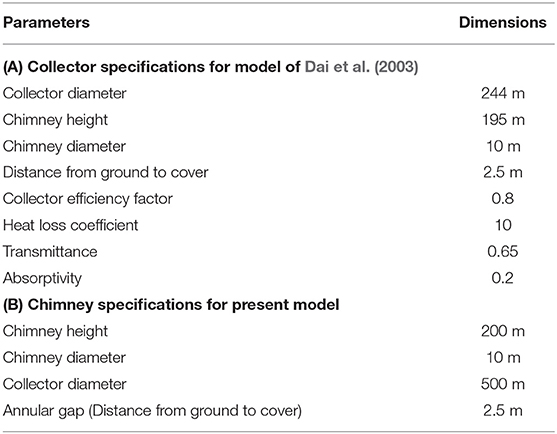
Table 4. Dimensions and parametric specifications of the Solar Chimney for Manzaranes plant and present model.
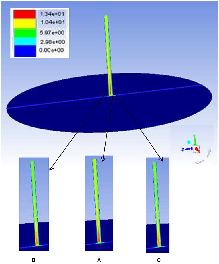
Figure 6. Velocity contours for the solar chimney considered as per Manzaranes geometry (A) Central plane, (B) r = 4 m, and (C) r = −4 m.
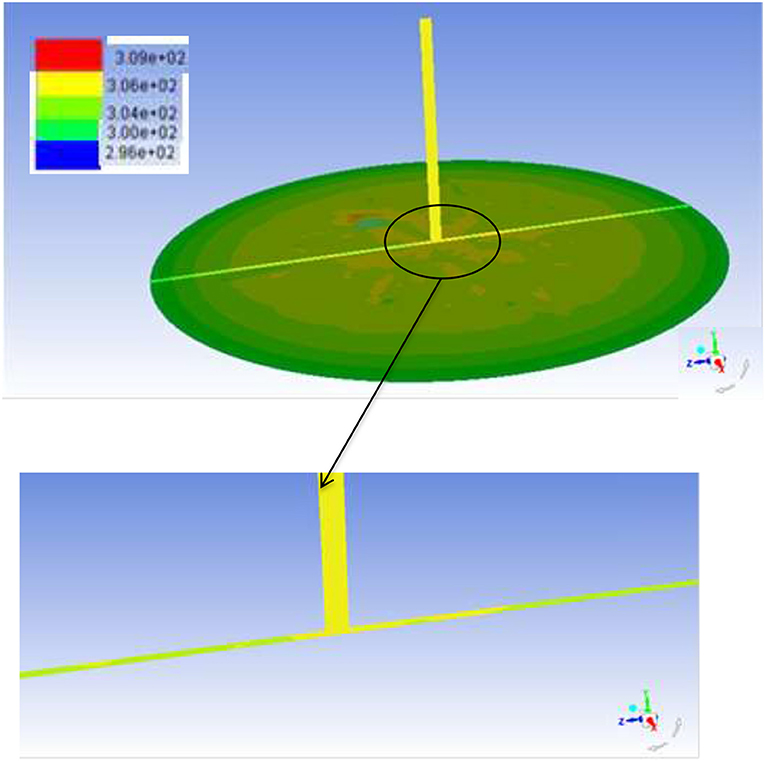
Figure 7 shows temperature contours of the entire collector surface, and also depicts the vertical centerline temperatures (which includes the temperatures of the space between ground and glass surface as well as the chimney). Clearly, the temperatures increase from 296 to 310 K as we reach the chimney inlet (as can be seen in the zoomed in figure).
The predicted results of both velocity and temperature were in good agreement with Ming et al. (2008) (v = 10 m/s; ΔT = 4.5 K), which they have predicted for an irradiance of 200 W/m2 and for a chimney whose collector is half as than that of the current chimney. The temperature difference is found to be around 10 K while mean velocities were found to be around 12 m/s. Higher temperature differences and velocities as compared to Ming et al. (2008) obtained in the present simulation is attributed to the larger collector area.
Effect of Chimney Height and Collector Diameter on Power Generated
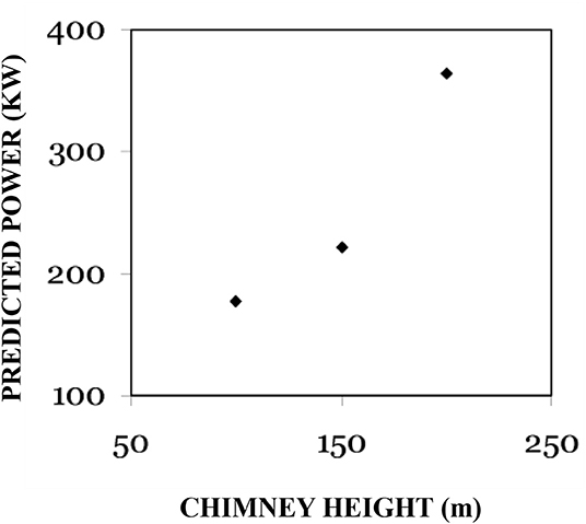
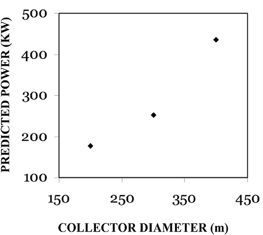
To study the effect of height and collector diameter on the performance of the chimney in terms of power generated two cases have been considered namely (a) constant collector diameter D = 500 m with variation in height from 50 to 200 m; (b) constant height H = 200 m with variation in diameter from D = 150 m to 500 m. The irradiance for the simulations was selected to be 1,000 W/m2. CFD simulations were carried out to understand the effect of chimney height on the generated power. The collector area was considered constant (D = 500 m) for these simulations. As observed, the power generated increased exponentially with chimney height (Figure 8). Simulations were carried for the height up to 200 m. The predicted power for a height of 200 m was 370 KW. Further, the power generated was also dependant on the collector area. Figure 9 shows that the predicted power increases as the collector area increases in an exponential manner. The trends were similar to studies of Koonsrisuk and Chitsomboon (2009). A maximum power up to 450 KW can be obtained with a collector diameter of 500 m. The exponential increase in power was seen for both increase in chimney height with constant collector diameter as well as increase in collector diameter with increasing chimney height. This increase could be attributed to the increase in central velocity at the node for both the cases. From Equation 4, total power was observed to be directly proportional to the velocity and since the velocity increases exponentially the power also increases exponentially. The values of power generated were much higher due to the high temperature differences considered and therefore, higher velocities at chimney inlet were predicted. It was evident from the predictions that solar irradiation during the day was much higher for such power generation to occur.
Diurnal Variations of Power Generated
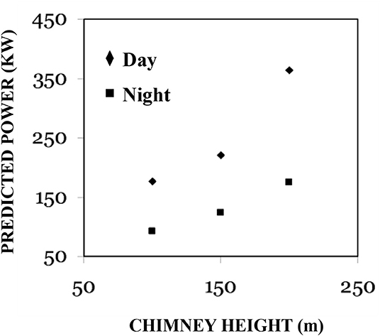
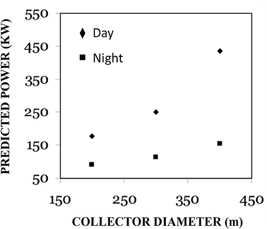
In countries which receive considerable sunlight throughout the year, the maximum and minimum temperatures throughout 24 h may fluctuate within 25oC. Hence, CFD simulations were performed with temperature of 45oC during the day and 20oC during the night. The temperatures were chosen in close resemblance to places in India, which receive the most sun radiations across the year (Deccan Plateau). The solar irradiance was chosen as 1,000 W/m2 during the day. Though the ambient temperature during night might be low, the stored heat of the ground would keep a surface temperature higher than the ambient temperature. Hence, suitable temperature difference has been taken accordingly. Parameters chosen for the variation are the chimney height and the total collector diameter. A trend of the predictions were similar to those described in the previous section (Figures 10, 11) especially during the day time. This trend indicates that the power generated increases exponentially with increase in chimney height and collector diameter. However, during the night, increase in the predicted power is marginal with an increase in either the collector diameter or chimney height. Interestingly, the increase in power generated for increase in height during night time is better than the increase in collector diameter.
Conclusions
Solar Chimney is one of the unexplored areas in the possible option in the field of renewable solar energy utilization. CFD can prove to be a useful tool to build confidence in the design and implementation of a solar chimney. Hence, a CFD model has been developed for a case in the literature. The model was validated with the experimental data in the literature and a good agreement was found. Flow patterns in the solar chimney suggested that peak velocities up to 11 m/s can be obtained for the temperature and dimensions of the chimney under consideration. A parametric study was performed for the solar chimney to assess overall power generated for two combinations, (a) by varying the height of the chimney (H = 50 to 200 m) at a constant collector diameter of 500 m and (b) by varying the collector diameter from 150 to 500 m for a constant height of 200 m. It was observed that for both cases the power increases exponentially as the collector diameter increases. This can be attributed to increase in central velocity at the chimney inlet where an updraft is experienced.
Another important aspect regarding prediction of power during the diurnal variations was attributed in the present paper. An important conclusion from the predicted results can be drawn that the increase in power in the night is marginal when collector diameter is increased for a fixed height. Variation of height for a fixed collector diameter gives a better trend of increase in power. The overall conclusion would be to increase the height keeping a standard collector diameter. Secondly, ways and means to find materials to store heat during the day time for the night time would help maintain the consistency in power generation over entire 24 h cycle and reduce uncertainty. As seen in literature, survey researchers have been trying to use heat storage materials and perform simulations for day time and improve the power generation. The present work actually also emphasizes that conditions during the night needs to be emphasized to see the effect of heat storage materials on the performance of power generated during night time.
Data Availability Statement
The datasets generated for this study are available on request to the corresponding author.
Author Contributions
AG: conceptualization, methodology, data curation, investigation, writing original draft, writing, review, and editing. SD: conceptualization, investigation, and review.
Conflict of Interest
The authors declare that the research was conducted in the absence of any commercial or financial relationships that could be construed as a potential conflict of interest.
Acknowledgments
The authors would like to acknowledge the inputs provided by Professor A. B. Pandit during this work.
Footnotes
1. ^ANSYS FLUENT 17.0 Theory Guide. ANSYS, Inc.
References
Bernardes, M. A., dos, S., Weinrebe, A., and Voß, G. (2003). Thermal and technical analyses of solar chimneys. Solar Energy 75, 511–524. doi: 10.1016/j.solener.2003.09.012
Chitsomboon, T. (2001). A validated analytical model for flow in solar chimney. Int. J. Renew. Energy Eng. 3, 339–346.
Dai, Y. J., Huang, H. B., and Wang, R. Z. (2003). Case study of solar chimney power plants in Northwestern regions of China. Renew. Energy 28, 1295–1304. doi: 10.1016/S0960-1481(02)00227-6
Fasel, H., Shams, E., and Gross, A. (2012). “CFD analysis for solar chimney power plants,” in 9th International conference on Heat Transfer Fluid Mechanics and Thermodynamics (Malta).
Filkoski, R. V., Stojkovski, F., and Stojkovski, V. (2013). “A CFD study of a solar chimney power plant operation,” in Proceedings of SEEP 2013 (Maribor).
Gholamalizadeh, E., and Kim, M.-H. (2014). Three-dimensional CFD analysis for simulating the greenhouse effect in solar chimney power plants using a two-band radiation model. Renew. Energy 63, 498–506. doi: 10.1016/j.renene.2013.10.011
Haaf, W. (1984). Solar chimneys, Part II: Preliminary test results from the Manzanares pilot plant. Int. J. Solar Ener. 2, 141–161. doi: 10.1080/01425918408909921
Hassan, A., Ali, M., and Waqas, A. (2018). Numerical investigation on performance of solar chimney power plant by varying collector slope and chimney diverging angle. Energy 142, 411–425. doi: 10.1016/j.energy.2017.10.047
Koonsrisuk, A., and Chitsomboon, T. (2009). Partial geometric similarity for solar chimney power plant modeling. Solar Energy 83, 1611–1618. doi: 10.1016/j.solener.2009.05.011
Koonsrisuk, A., and Chitsomboon, T. (2013). Mathematical modeling of solar chimney power plants. Energy 51, 314–322. doi: 10.1016/j.energy.2012.10.038
Ming, T. Z., Liu, W., Pan, Y., and Xu, G. L. (2008). Numerical analysis of flow and heat transfer characteristics in solar chimney power plants with energy storage layer. Energy Conver. Mange. 49, 2872–2879. doi: 10.1016/j.enconman.2008.03.004
Padki, M. M., and Sherif, S. A. (1989a). “Solar chimney for medium-to-large scale power generation,” in Proceedings of the Manila International Symposium on the Development and Management of Energy Resources, Vol. 1 (Manila), 423–437.
Padki, M. M., and Sherif, S. A. (1989b). “Solar chimney for power generation in rural areas,” in Seminar on Energy Conservation and Generation through Renewable Resources (Ranchi), 91–96.
Padki, M. M., and Sherif, S. A. (1999). On a simple analytical model for solar chimneys. Int. J. Energy Res. 23, 345–349. doi: 10.1002/(SICI)1099-114X(19990325)23:4<345::AID-ER485>3.0.CO;2-Z
Panse, S. V., Jadhav, A. S., Gudekar, A. S., and Joshi, J. B. (2011). Inclined solar chimney for power production. Energy Conver. Manage. 52, 3096–3102. doi: 10.1016/j.enconman.2011.05.001
Pasumarthi, N., and Sherif, S. A. (1998a). Experimental and theoretical performance of a demonstration solar chimney model - part I: mathematical model development. Int. J. Energy Res. 22 277–288. doi: 10.1002/(SICI)1099-114X(19980310)22:3<277::AID-ER380>3.0.CO;2-R
Pasumarthi, N., and Sherif, S. A. (1998b). Experimental and theoretical performance of a demonstration solar chimney model - part II: experimental and theoretical results and economic analysis. Int. J. Energy Res. 22 443–461. doi: 10.1002/(SICI)1099-114X(199804)22:5<443::AID-ER381>3.0.CO;2-V
Pretorius, J. P., and Kroger, D. G. (2006). Solar chimney power plant performance. J Solar Energy Engg. 128, 302–311. doi: 10.1115/1.2210491
Sangi, R., Amidpour, M., and Hosseinizadeh, B. (2011). Modeling and numerical simulation of solar chimney power plants. Solar Energy 85, 829–838. doi: 10.1016/j.solener.2011.01.011
Shahreza, A. R., and Imani, H. (2015). Experimental and numerical investigation on an innovative solar chimney. Energy Conserv. Manage. 95, 446–452. doi: 10.1016/j.enconman.2014.10.051
Tingzhen, M., Wei, L., and Guoliang, X. (2006). Analytical and numerical investigation of the solar chimney power plant systems. Int J. Energy Res. 30, 861–873. doi: 10.1002/er.1191
Zhou, X., Yang, J., Xiao, B., and Hou, G. (2007). Experimental study of temperature field in a solar chimney power setup. Appl. Ther. Eng. 27, 2044–2050. doi: 10.1016/j.applthermaleng.2006.12.007
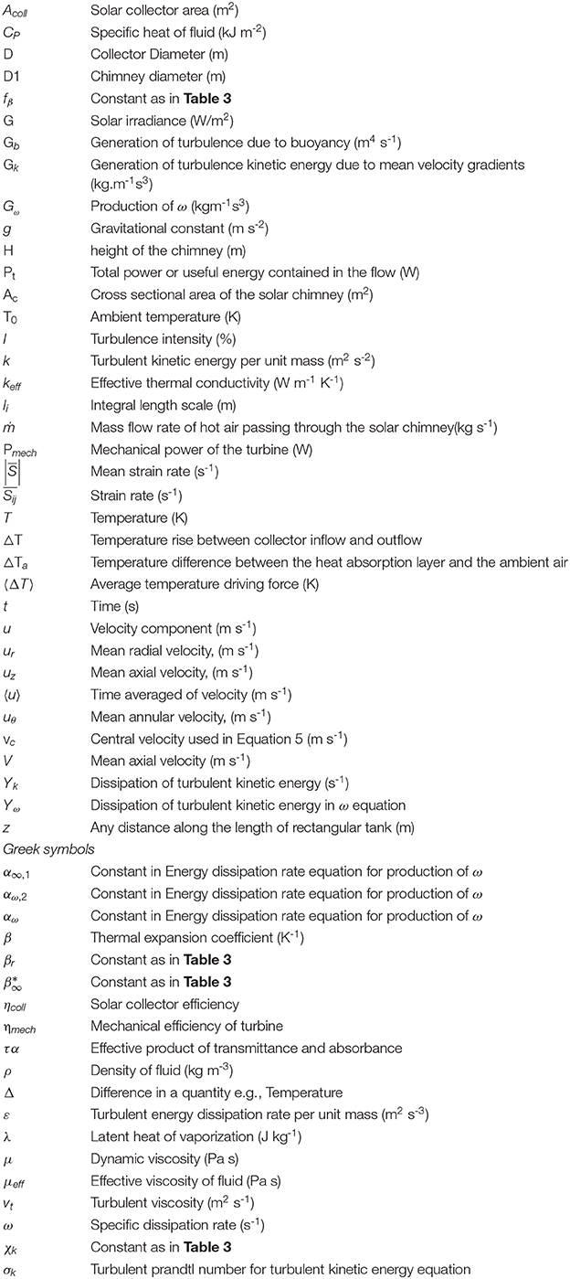
Nomenclature
Keywords: solar chimney, CFD, heat transfer, energy efficiency, mathematical modeling
Citation: Ganguli AA and Deshpande S (2020) Three Dimensional CFD Studies of a Solar Chimney: Effect of Geometrical Parameters and Diurnal Variations on Power Generated. Front. Chem. Eng. 2:2. doi: 10.3389/fceng.2020.00002
Received: 04 December 2019; Accepted: 10 March 2020;
Published: 07 April 2020.
Edited by:
José María Ponce-Ortega, Michoacana University of San Nicolás de Hidalgo, MexicoReviewed by:
Fabricio Nápoles, Michoacana University of San Nicolás de Hidalgo, MexicoCarlos Rubio-Maya, Michoacana University of San Nicolás de Hidalgo, Mexico
Luis Fabián Fuentes-Cortés, Technological Institute of Celaya, Mexico
Copyright © 2020 Ganguli and Deshpande. This is an open-access article distributed under the terms of the Creative Commons Attribution License (CC BY). The use, distribution or reproduction in other forums is permitted, provided the original author(s) and the copyright owner(s) are credited and that the original publication in this journal is cited, in accordance with accepted academic practice. No use, distribution or reproduction is permitted which does not comply with these terms.
*Correspondence: Arijit A. Ganguli, Z2FuZ3VsaWFyaWppdEBnbWFpbC5jb20=
 Arijit A. Ganguli
 Sagar Deshpande2
