 Martino Di Serio
 Vincenzo Russo
 Elio Santacesaria
 Riccardo Tesser
- 1Department of Chemical Sciences, University of Naples Federico II, Naples, Italy
- 2Eurochem Engineering Srl, Milan, Italy
The most recent reactor technology to produce non-ionic surfactants via ethoxylation reaction is illustrated in the present work. The most advanced reactors are deeply illustrated for what concerns the working principle and the main performance. In detail, Venturi Loop Reactor (VLR), Spray Tower Loop Reactor (STLR) and Enhanced Loop Reactor (ELR) are depicted, and the related performance compared. ELR shows the highest flexibility, to reach the desired ethoxylation degree, and at the same time good performances comparable with the VLR. Moreover, ELR allows to reach high ethoxylation degree, as in this condition, a good mixing, in the case of high liquid expansion, is difficult to be achieved with the other reactors. Thus, it is possible to work at higher ethoxylation degree respecting safety issues. Finally, a comprehensive model was proposed to describe quantitatively the mentioned reactors. The model is characterized by a general validity and can be easily adapted to each specific reactor configuration.
Introduction
Starting from the patent assigned to I.G. Farbenindustrie (Schoeller and Witttwer, 1934) the production of non-ionic surfactant obtained by ethoxylation of fatty organic substances containing at least one reactive hydrogen has increased enormously. For example, nowadays more than 50% of world consumption of surfactants for household detergents application is represented by alcohol ethoxylates and alcohol ethers sulfates (Janshekar et al., 2010).
From the first used stirred jacketed reactor, during the time, new reactor types have been proposed on the market. The increase in safety, productivity and selectivity has been the driving force for the new reactor designs (Di Serio et al., 2005; Salzano et al., 2007; Di Serio, 2019) and we can consider the technological improvement in the ethoxylation reactors as a clear example of the process intensification (Stankiewicz and Moulijn, 2000).
Notwithstanding the new quite recent proposals for continuous reactor (Tesser et al., 2020), the ethoxylated products synthesis is still largely based on fed-batch reactors technology in various configurations.
A first classification of these reactors is possible by considering the dispersed phase (Dimiccoli et al., 2000). The ethylene oxide is bubbled in the liquid phase (stirred tank reactor, STR, or Venturi Loop Reactor, VLR (see Figure 1), or the liquid is sprayed in an atmosphere of gaseous ethylene (Spray Tower Loop Reactor, STLR) (see Figure 2). In general, the heat exchanger is located outside the reactor, on the circulation line, and a liquid recirculation pump is present, also in the case of the simple mixed reactor.
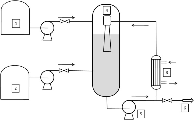
FIGURE 1. Venturi Loop Reactor (VLR). 1–2: tanks, 3: heat exchanger; 4: ejector; 5: recirculating pump; 6: outlet stream.
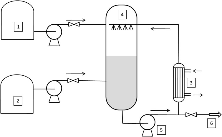
FIGURE 2. Flowsheet of the Spray Tower Loop Reactor (STLR). 1–2: tanks, 3: heat exchanger; 4: spray nozzles; 5: recirculating pump; 6: outlet stream.
The main problem for this process is the difficulty in eliminating or minimizing mass-transfer and heat-transfer limitations, which are generally associated with conventional stirred tank alkoxylation reactors. The use of Venturi Loop Reactor (VLR) or Spray Tower Reactor (STLR) can solve these problems, but they still have some drawbacks (Di Serio et al., 2005):
(1) STLR: to achieve the maximum productivity in STLR a high recirculation flow rate is necessary. The required power input for a spray tower loop reactor is greater than that for a Venturi loop reactor.
(2) VLR: Venturi loop reactor has some drawbacks related to the rigid geometrical parameters that must be satisfied as concerns the dimensions of the reactor, the liquid level, and the nozzle length. As a matter of fact, the plants where VLR technology is used have in general two reactors: the first one works in the initial stage of the reaction (when the liquid level is low), and the other one is used for achieving high ethylene oxide/substrate molar ratio that corresponds to high increase in volume. Moreover, in the case of large reactors, the behavior of VLR can also become like that of STLR in terms of the power input required for liquid recirculation.
To overcome these drawbacks, a new reactor was proposed the Enhanced Loop Reactor (ELR) (see Figure 3) that represents a combination of the two best previously used technologies: Spray-Tower-Loop Reactor and the Venturi-Loop Reactor (Santacesaria et al., 2018)1. Thus, the main novelty of this paper is to introduce and describe the ELR, comparing its performance with both STLR and VLR.
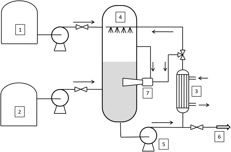
FIGURE 3. Sketch of the Enhanced Loop Reactor (ELR). 1–2: tanks, 3: heat exchanger; 4: spray nozzles; 5: recirculating pump; 6: outlet stream; 7: ejector.
In this paper we will compare the performances of the three cited technologies based on mathematical simulations of the reactors.
Description of the Reactors and the Related Mathematical Model
In the VLR, the pumped liquid passes through a nozzle that provides a high velocity jet of fluid to create suction of the gas. In a mixing tube, the high velocity jet attaches itself to the mixing tube wall, resulting in a rapid dissipation of kinetic energy, which creates an intensive mixing with the production of a fine dispersion of gas bubbles in the liquid phase. The two-phase mixture that “jets” into the reaction autoclave also causes intensive mixing. Considering that the Hatta number of ethoxylation reactions is less than one, a Venturi Loop Reactor can be simulated by assuming it as a well-stirred isothermal reactor (Di Serio et al., 2005).
In STLR, the sprayed liquid is dispersed in the form of small liquid drops flying into the alkylene oxide gaseous atmosphere. Drops emerging from an efficient spray nozzle resulted as internally well-mixed drops, leading to a very high mass-transfer rate, and if the average flight time of the drops is long enough, these drops are completely saturated at the end of their flight (Tesser et al., 2020). The reaction occurs in the liquid column (Santacesaria et al., 1990; Santacesaria et al., 1999) and can be neglected the drops contribution to the reaction, since the flight time is extremely short if compared to the residence time in the liquid column. The liquid column can then be modeled assuming it as a plug-flow reactor in transient conditions as the concentration of dissolved alkoxyde changes with time and along the column itself. Hence, in these reactors, mass transfer and chemical reaction occur separately in two distinct zones: the mass-transfer zone, corresponding to the zone of drops flying across the gaseous atmosphere, and the reaction zone, corresponding to the slowly flowing liquid-phase collected at the bottom of the reactor and recirculated back to the spray nozzle (Di Serio et al., 2005).
The ELR has been simulated considering it as a STLR reactor on which, in the lower part of the reactor, is placed an ejector. In this case the total recirculating flow is divided, after the heat exchanger, in two streams: one of which is fed to the spray nozzle and the second to the ejector. Furthermore, the liquid flowing in the ejector suck up the gas from the reactor head and disperses it in the liquid phase in the form of bubbles which, rising upwards in the liquid column, further stir the liquid phase.
In this case the ELR, when the ethoxylation reaction is started, behaves like a STLR and when the liquid level reaches a prefixed value, circulation flow is splitted and the ejector is started. In this phase the behavior of the ELR is more similar to a VLR. This reactor configuration has the effect to merge the two most important advantage of both STLR and VLR: it is possible start the production with a very low quantity of substrate (like in the case of STLR) and a high efficiency in mass transfer is achieved with low power input (like in the case of VLR).
More details about the VLR and STLR mathematical model are reported elsewhere (Di Serio et al., 2005) and here only the main structure of the model is presented. The liquid column in the reactor can be assumed with a plug-flow behavior but is in transient conditions as the concentration changes both along the time and along the axial direction. For modeling purposes, the reactor can be schematized as a series of well mixed cells or liquid portions distributed along the liquid column, according to the well-known compartmental models (Egedy et al., 2013; Haag et al., 2018). In the scheme reported in Figure 4 the cells scheme related to ELR configuration is reported.
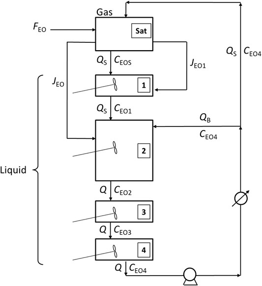
FIGURE 4. Modeling scheme to describe the Enhanced Loop Reactor (ELR).
From this scheme it is possible to appreciate the characteristics of the reactor. After the heat exchanger on the circulation line, the flow is splitted into two portions: one of these is fed to the spray and the other one is sent to the ejector placed in the lower part of the reactor.
As revealed in Figure 4, four cells were assumed as an example of discretization. The model is certainly general and provides the possibility to impose a user-defined number of compartments, depending on the axial dispersion degree that would describe the system, as in the general tank-in-series model. In the specific case, we assumed four cells as the liquid phase is well mixed by the ejector present in the bottom of the reactor. Thus, due to the mixing efficiency of the ejector, the liquid column is assumed as constituted by four separate cells which behavior is that of a dynamic CSTR reactor: the first upper cell one receive the liquid more or less saturated with EO in the spray chamber; the majority of the liquid is located in the cells two that is well mixed by the ejector; two additional relatively small cells three and four are located in the lower part of the reactor and become important in the final part of the operations, when the height of the liquid column is increased significantly. More generally, a higher number of cells can be considered both above and below the central cell two associated to the ejector.
In the scheme of Figure 4 also gas-liquid mass transfer flows are reported: the first, JEO1 is related to the spray chamber in which gaseous EO is transferred from gas-phase to liquid droplets emerging from nozzles; the second, JEO, is due to the gas suction from ejector that transfer EO directly to the liquid phase of cell 2.
For the development of a general model based on the scheme reported in Figure 4, some assumptions can be adopted, as in the following points:
(1) The spray nozzle is considered with a full efficiency in saturation. In the spray chamber, the entering liquid is fully saturated with EO.
(2) The flow of liquid phase in the liquid column is simulated as a series of CSTR reactors (cells or compartments). The different distribution of cells volume can be used to represent different reactor configuration and fluid-dynamic conditions. For instance, as for the general tank-in-series model, depending on the axial dispersion degree, it is possible to choose a different number of compartments. In detail, a plug-flow fluid-dynamics can be simulated by a theoretically infinite number of cells, while a stirred tank with only one compartment. Thus, a high number of equal cells is used for a STLR while the case of ELR reactor the scheme of cells in Figure 4 is more suitable.
(3) The expansion of the system volume, that occurs as ethoxylation proceeds, is assumed as equally distributed on all the cells in the reactor.
(4) The overall volumetric circulation flowrate, Q, is assumed constant.
(5) The feed of liquid EO from the external tank is assumed as completely vaporized in the saturation chamber of the reactor.
(6) Some properties of the reacting mixture are assumed as constants or averaged with temperature, such as specific heat, heat of vaporization.
The reactor is perfectly insulated and no heat exchange with the surroundings is present.
(7) The heat exchanger installed on the circulation line is assumed with infinite exchange capacity and the outlet temperature is fixed at a predefined value TS.
Under these assumptions, the model of a generic cell is represented by a mass and heat balance equations as follows:
The specific model for the reactor can then be developed based on Eqs 1, 2 by considering for the specific reactor configuration.
A first differential equation in the model is used for calculating, as a global check, the overall quantity of ethylene oxide fed to the reactor per mole of substrate, during the entire fed-batch operation. This represent a counter and is defined as:
Referring to the scheme in Figure 4, the mass balance for EO in this section of the reactor is:
where the mass transfer flows are defined by the following relations:
Another important relation if the account for the overall quantity of reacted EO. This equation can be written as follows:
where:
As said before, the liquid EO is stored in a tank pressurized with an inert gas (usually nitrogen) and is fed to the reactor directly from this tank. The inert gas dissolved into liquid EO is then continuously fed to the reactor resulting in an accumulation of inert during the operation. The semi batch mass balance on inert gas is then:
Material balance on cells is slightly different from one cell to another. The following differential equations represent the mass balances for cell 1 (Eq. 10), cell 2 (Eq. 11) and cells three and 4 (Eq. 12).
In analogy with the material balance equations, the energy balance on the compartments can be written. For the first cell the energy balance assumes the following form:
For the central cell number two the energy balance is slightly different:
The temperature of the two last bottom cells can de described by the two following ODEs:
The group of relations consisting the model represent a system of coupled ordinary differential equations that must be integrated in time starting from a suitable initial condition for each of the related dependent variables. However, the mentioned ODEs system cannot be solved without the addition of other algebraic constitutive equations that describe auxiliary variables such as pressure, liquid, and gas volume, EO solubility, reactive mixture density, kinetic expression and related parameters, etc. Moreover, some relations are necessary to calculate the right initial conditions in the reactor.
Initial nitrogen amount in the reactor can be evaluates as:
At each time step, the total pressure in the gas phase of the reactor can be evaluated, by the following relation:
For what concerns the kinetics, in the case of ethoxylation performed by using fatty alcohols as a starter in the presence of an alkaline catalyst, the following equation for overall EO consumption can be used (Santacesaria et al., 1992a; Santacesaria et al., 1992b; Di Serio et al., 1995; Di Serio et al., 2005):
where [CAT] is the catalyst concentration and [EO] is the liquid ethylene oxide concentration. In the simulations we have used the kinetic parameter recently proposed by Amaral and Giudici (Amaral and Giudici, 2011), who confirmed the reliability of our model in the description of STLR and proposed more accurate kinetic data for dodecanol ethoxylation:
To calculate the catalyst concentration [CAT] and liquid ethylene oxide concentration [EO] the physical (the EO solubility data and the density of the substrate and of the products) parameters have been calculated using previously reported equations and parameters (Santacesaria et al., 1992a; Santacesaria et al., 1992b; Di Serio et al., 1995; Di Serio et al., 2005).
Comparison of Reactors
The comparison of the reactors was done considering reactor with the same total volume and using the same total recirculating flow. In the case of VLR we idealize the reactor considering it well mixed in all the range of the simulation. As we said before, this is not true: at the beginning it is often necessary use a smaller reactor and when in the reactor there is a high amount of liquid also zones could exist in which the liquid is not well mixed.
In Figures 5, 6, the main results of the simulations are reported. For instance, the growth ratio of the ethoxylated product is reported as a function of the reaction time. The growth ratio is defined as the ethylene oxide moles added in the product per mole of substrate. Moreover, p is defined as the total pressure of the system.
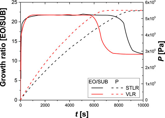
FIGURE 5. Calculated values of growth ratio and total pressure, in VLR, STLR operating in the same conditions. Reactor volume: 20 m3; total recirculating flow: 210 m3/h; maximum operating pressure: 5.5 bar; initial Nitrogen pressure: 1.2 bar; starter (dodecanol):500 kg; catalyst (KOH): 8 kg; exiting heat exchanger temperature: 178°C; final growth ratio:20.5.
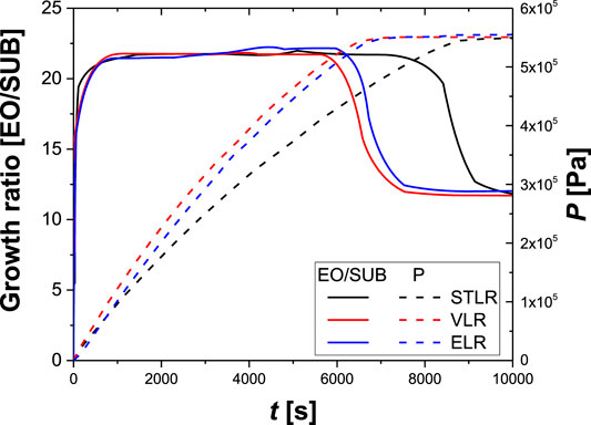
FIGURE 6. Calculated values of growth ratio and total pressure, in VLR, STLR, ELR operating in the same conditions. Reactor volume: 20 m3; total recirculating flow: 210 m3/h; maximum operating pressure: 5.5 bar; initial Nitrogen pressure: 1.2 bar; starter (dodecanol):500 kg; catalyst (KOH): 8 kg; exiting heat exchanger temperature: 178°C; final growth ratio:20.5.
The VLR has better performances than the STLR (see Figure 5), as in VLR the ethylene oxide average concentration in the liquid phase is higher than STLR. Since STLR behaves as a plug-flow reactor, it depletes ethylene oxide in the first upper portion of the liquid phase, while VLR, being a stirred vessel, increases the average EO content. However, the Venturi loop reactor has some drawbacks that are related to the necessity to have the geometrical parameters of the Venturi-type ejector within defined limits. As the simulations were conducted to keep a constant pressure of the system, the growth ratio approaches to a plateau value when the consumption of ethylene oxide decreases, indicating the stop of the ethylene oxide feed. Thus, the overall pressure decreases reaching the set value of the inert gas.
In ethoxylation reactions, as the liquid strongly increases as the reaction and a unique Venturi loop device becomes inadequate to handle the variation condition for the liquid level. For this reason, a multijet arrangement, with the jet starting to operate at different liquid levels, must be used for VLR in the ethoxylation.
In Figure 6 the performance of the ELR is reported. In this case the total recirculating flow was divided in two parts when liquid volume in the reactor was 3 m3. The one that supplied the spray nozzle was the 25% of the total while the remaining amount supplied the ejector.
As can be seen, the ELR has the same performances of the VLR, as they provide a similar mixing to the liquid phase, thus a similar ethylene oxide content. However, the Enhanced Loop Reactor has a high flexibility of the gas-liquid contacting devices that permit constant performances of the reactor during all the course of the production process and growth ratio up to 80 (see Figure 6).
Conclusion
In the present paper, the behavior of different reactors for the ethoxylation of organic substrates was presented. In particular, the performance of three reactors was compared: Venturi Loop Reactor (VLR), Spray Tower Loop Reactor (STLR) and Enhanced Loop Reactor (ELR). The main conclusion of the present investigation is that ELR shows the highest flexibility among the presented approaches. In particular, the performance of ELR can be considered comparable with VLR, but it allows to reach higher ethoxylation degree, that means a higher liquid expansion, warranting in the meantime a good mixing of such high volumes. This fact allows to work at full ethylene oxide per-pass conversion, with consequent improvements in the process safety and control.
The presented modeling approach allows the quantitative description of the three reactors. This model, bases on a cell approach, allows to properly design reactors working at a desired ethoxylation degree. In perspective, with such a model, the operation conditions could be optimized, e.g. the split ratio between the flow rates feeding the spray nozzle and the ejector placed on the bottom of the reactor.
Data Availability Statement
The original contributions presented in the study are included in the article/Supplementary Material, further inquiries can be directed to the corresponding author.
Author Contributions
MS and RT wrote the original draft of the manuscript with support from ES. The main conceptual ideas were drawn from the interactions between MS and RT. The development of the artworks, the data elaboration and the formal analysis were conducted by VR and RT. The final draft was corrected by all the authors.
Conflict of Interest
ES was employed by Eurochem Engineering Srl.
The remaining authors declare that the research was conducted in the absence of any commercial or financial relationships that could be construed as a potential conflict of interest.
Abbreviations
CAT, catalyst; ELR, enhanced loop reactor; EO, ethylene oxide; STLR, spray tower loop reactor; STR, stirred tank reactor; SUB, substrate; VLR, venturi loop reactor.
Footnotes
1https://www.desmetballestra.com/dsc/surfactants/ethoxylation-propoxylation
List of Symbols
Ci,j Concentration of component i in cell j [mol/m3]
Count Amount of EO fed to the reactor [-]
F EO molar feed rate [mol/s]
Cp Specific heat [J/(kg K)]
H Henry’s constant [Pa m3/mol]
J Mass transfer rate [mol/(m3 s)]
k Kinetic constant [m3/(mol s)]
n Amount of substance [mol]
P Pressure [Pa]
Q Volumetric flow-rate [m3/s]
R Reaction rate [mol/(m3 s)]
S Overall quantity or reacted EO [mol/s]
t Time [s]
T Temperature [K]
V Volume [m3]
Greek Symbols
β Mass transfer coefficient [1/s]
ΔHr Reaction enthalpy [J/mol]
ρ Fluid density [kg/m3]
References
Amaral, G. M., and Giudici, R. (2011). Kinetics and modeling of fatty alcohol ethoxylation in an industrial spray loop reactor. Chem. Eng. Technol. 34 (10), 1635–1644. doi:10.1002/ceat.201100215
Di Serio, M. (2019). Chemical reaction engineering as a bridge between nano and macro world. Front. Chem. Eng. 1, 1–2. doi:10.3389/fceng.2019.00002
Di Serio, M., Tesser, R., Felippone, F., and Santacesaria, E. (1995). Ethylene oxide solubility and ethoxylation kinetics in the synthesis of nonionic surfactants. Ind. Eng. Chem. Res. 34, 4092–4098. doi:10.1021/ie00038a052
Di Serio, M., Tesser, R., and Santacesaria, E. (2005). Comparison of different reactor types used in the manufacture of ethoxylated, propoxylated products. Ind. Eng. Chem. Res. 44, 9482–9489. doi:10.1021/ie0502234
Dimiccoli, A., Di Serio, M., and Santacesaria, E. (2000). Mass transfer and kinetics in spray-tower-loop absorbers and reactors. Ind. Eng. Chem. Res. 39, 4082–4093. doi:10.1021/ie000137y
Egedy, A., Varga, T., and Chován, T. (2013). Compartment model structure identification with qualitative methods for a stirred vessel. Math. Comput. Model. Dyn. Syst. 19 (2), 115–132. doi:10.1080/13873954.2012.700939
Haag, J., Gentric, C., Lemaitre, C., and Leclerc, J. (2018). Modelling of chemical reactors: from systemic approach to compartmental modelling. Int. J. Chem. React. Eng. 16 (8), 1–22. doi:10.1515/ijcre-2017-0172
Janshekar, H., Rizvi, S. Q. A., and Inoguchi, Y. (2010). Surfacatant household detergents and their raw material. CEH Report.
Salzano, E., Di Serio, M., and Santacesaria, E. (2007). The evaluation of risks of ethoxylation reactors. Proc. Saf. prog. 26 (4), 304–311. doi:10.1002/prs.10212
Santacesaria, E., Di Serio, M., Garaffa, R., and Addino, G. (1992a). Kinetics and mechanisms of fatty alcohol polyethoxylation. 1. The reaction catalyzed by potassium hydroxide. Ind. Eng. Chem. Res. 31, 2413–2418. doi:10.1021/ie00011a001
Santacesaria, E., Di Serio, M., Garaffa, R., and Addino, G. (1992b). Kinetics and mechanisms of fatty alcohol polyethoxylation. 2. narrow-range ethoxylation obtained with barium catalysts. Ind. Eng. Chem. Res. 31, 2419–2421. doi:10.1021/ie00011a002
Santacesaria, E., Di Serio, M., Lisi, L., and Gelosa, D. (1990). Kinetics of nonylphenol polyethoxylation catalyzed by potassium hydroxide. Ind. Eng. Chem. Res. 29, 719–725. doi:10.1021/ie00101a002
Santacesaria, E., Tesser, R., and Di Serio, M. (2018). Polyethoxylation and polypropoxylation reactions: kinetics, mass transfer and industrial reactor design. Chin. J. Chem. Eng. 26 (6), 1235–1251. doi:10.1016/j.cjche.2018.02.020
Santacesaria, E., Di Serio, M., and Iengo, P. (1999). Mass transfer and kinetics in ehtoxylation spray tower loop reactors. Chem. Eng. Sci. 54, 1499–1504. doi:10.1016/s0009-2509(99)00042-1
Schoeller, C., and Witttwer, M. (1934). Assistants for the textile and related industries. US1970578.
Stankiewicz, A. I., and Moulijn, J. A. (2000). Process intensification: transforming chemical engineering. Chem. Eng. Prog. 96, 22–34.
Keywords: ethoxylation, reactors, reactor technology, non-ionic surfactants, scale-up
Citation: Di Serio M, Russo V, Santacesaria E and Tesser R (2021) The Evolution of the Fed Batch Ethoxylation Reactors to Produce the Non-Ionic Surfactants. Front. Chem. Eng. 3:644719. doi: 10.3389/fceng.2021.644719
Received: 21 December 2020; Accepted: 01 February 2021;
Published: 15 March 2021.
Edited by:
Giuseppina Iervolino, University of Salerno, ItalyReviewed by:
Attila Egedy, University of Pannonia, HungaryErnesto Salzano, University of Bologna, Italy
Francesco Maestri, Politecnico di Milano, Italy
Copyright © 2021 Di Serio, Russo, Santacesaria and Tesser. This is an open-access article distributed under the terms of the Creative Commons Attribution License (CC BY). The use, distribution or reproduction in other forums is permitted, provided the original author(s) and the copyright owner(s) are credited and that the original publication in this journal is cited, in accordance with accepted academic practice. No use, distribution or reproduction is permitted which does not comply with these terms.
*Correspondence: Riccardo Tesser, cmljY2FyZG8udGVzc2VyQHVuaW5hLml0