 Matteo Ambrosetti
 Alessandra Beretta
 Enrico Tronconi
- Dipartimento di Energia, Laboratory of Catalysis and Catalytic Processes, Politecnico di Milano, Milano, Italy
The use of electric energy as an alternative system to provide heat of reaction enables the cut-off of CO2 emissions of several chemical processes. Among these, electrification of steam methane reforming results in a cleaner production method of hydrogen. In this work, we perform for the first time a numerical investigation of a compact steam reforming unit that exploits the electrical heating of the catalyst support. First, for such unit we consider the optimal thermodynamic conditions to perform the power to hydrogen conversion; the process should be run at atmospheric pressure and in a close temperature range. Then, among possible materials currently used for manufacturing structured supports we identify silicon carbide as the best material to run electrified steam reforming at moderate voltages and currents. The temperature and concentration profiles in idealized units are studied to understand the impact of the catalyst geometry on the process performances and open-cell foams, despite lower surface to volume show the best potential. Finally, the impact of heat losses is analyzed by considering different operative conditions and reactor geometries, showing that it is possible to obtain relatively high thermal efficiencies with the proposed methodology.
Introduction
CO2 is a well-known greenhouse gas and its concentration raised significantly in the last decades of the century due to human activities. To mitigate the increasing worldwide CO2 emissions, drastic changes in energy generation technology and energy utilization in key sectors of the industry are required. The Sustainable Development Scenario, issued by International Energy Agency (IEA), states that, to reduce the global temperature increase by 1.5°C, the energy and industrial sectors should reduce their CO2 emissions by 50% by 2050. This calls for a drastic change in the utilization of feedstocks, an increase of the efficiency of industrial processes of the chemical industry, and in the energy generation (International Energy Agency, 2021). Among possible interventions, the use of cleaner fuels is envisioned for several sectors including transportations and heating. Hydrogen is a carbon neutral fuel that can be used in substitution to conventional ones with reduced environmental impact (Bakhtyari et al., 2019).
Several methods like pyrolysis, electrochemical water splitting or conversion of the biomass can used for the production of clean H2, but the large share of production relies on the reforming of different hydrocarbons (Bakhtyari et al., 2019). Methane steam reforming (MSR) is a very energy intensive process for the generation of syngas and hydrogen, to be used in several processes like ammonia and methanol synthesis. It impacts for over 3% of the global CO2 emissions (Wismann et al., 2019a). The process is typically run in multi-tubular reactors with 12–15 m long tubes, having external diameters in the range 7–12 cm loaded with Nickel pelletized catalyst. The process is run at high temperature and pressure in order to obtain almost complete methane conversions (Rostrup-Nielsen, 1984). Such process is optimized for large scale production. In these conditions, the catalyst, in the form of pellets, is able to grant adequate convective heat transfer properties thanks to high flow velocities (Dixon and Partopour, 2020). The heat is supplied by burning a significant amount of fuel - typically methane in air - in external burners that are aimed to transfer heat. Several solutions were proposed to reduce the CO2 emissions associated with the reforming process: the CO2 produced after the water-gas shift units can be separated with PSA units where the CO2 associated with the stack gases can be separated in scrubbing units (Pellegrini et al., 2020). CO2 then can be recycled to other uses or stored in liquid phase.
In view of distributed syngas and hydrogen production, an increasing demand of small-scale applications is apparent, however, key technological limitations hinder the direct scale-down of the MSR technology (Balzarotti et al., 2020). By using noble metal catalysts, at the small scale heat transfer in packed bed reactors becomes the bottleneck of the process, strongly limiting its productivity (Donazzi et al., 2008). An interesting possibility is represented by the adoption of structured catalysts, aimed at intensifying the heat transfer rates of the system, thus the overall productivity. As recently demonstrated (Balzarotti et al., 2019; Balzarotti et al., 2020), the adoption of conductive internals strongly reduces the thermal limitations of the system, increasing the conversion at fixed external temperature.
In the last decade, as a reaction to the growing CO2 emissions and to environmental policies applied in most of the developed countries, a very deep change in the energy generation scenario was observed with a rapid increase of energy produced from Renewable Energy Sources (RES), thanks to a rapid ascent of power generation from solar and wind (International Energy Agency, 2021). Nowadays, RES may cover in summer up to 30–40% of the total energy demand, at the expenses of traditional energy sources from fossil fuels (Colbertaldo et al., 2018). Renewable energy sources have consistently reduced the CO2 emissions associated with energy generation; however such a large share of aleatory units poses several problems in terms grid balancing especially in the daytime where the productivity of solar RES is concentrated. Solutions like inclusion of batteries and large share of smart grids are currently envisioned (Colbertaldo et al., 2018).
In this context, the possibility of transforming electric energy in chemical energy is considered among the most cost-efficient possibilities to compensate energy over-generation and to produce valuable feedstocks (Wismann et al., 2019a; Centi and Perathoner, 2021; Layritz et al., 2021). As an example, hydrogen can be produced by water splitting by electrolysis and is at the basis of clean combustion and of the production of several chemicals. Several technologies are present on the market, with overall efficiencies in the range 0.7–0.85 and with installed capacities of 0.1–1,000°Nm3 H2/h. Hydrogen produced by electrolysis can then be used for several purposes, ranging from low carbon heating to the synthesis of chemicals. (Peters et al., 2019; Thema et al., 2019).
However, this is not the only possible use of electrical energy for the production of chemicals. In particular is possible to envision some technologies to transform excess electric power into heat. Several transformation routes have been proposed, considering plasma reactors (Dinh et al., 2020), microwave heated reactors (Pérez-Camacho et al., 2015; Palma et al., 2020; de Dios García et al., 2021; Yan et al., 2021) and induction heated reactors (Roelofsen et al., 2020; Scarfiello et al., 2021).
Another alternative is the use of Joule heating to replace the fossil fuel combustion for endothermic chemical syntheses. This approach is being recently considered in several industrial fields (Palma et al., 2020). Recently, Wismann et al. (Wismann et al., 2019a; Wismann et al., 2019b) proposed an innovative solution for the production of syngas (H2 and CO) by running the conventional methane steam reforming using electric (Joule) heating instead of conventional methane co-firing to sustain the reforming reaction. This process may exploit the excess or renewable energy for the production of an H2 rich syngas, that can further be separated to obtain a stream of pure H2 or can be used as reactant for several processes. With this solution, it is expected to reduce by 20–50% the CO2 emissions associated with H2 production by steam reforming, resulting in a significant benefit for the environment (Wismann et al., 2019a; Wismann et al., 2019b). The reactor layout proposed by Wismann and coworker (Wismann et al., 2019a; Wismann et al., 2019b) consists in a stainless steel tube, whose ends are connected to a power generator and the tube acts as electrical resistance; the tube is coated with a thin layer of Nickel catalyst to promote the reforming reaction. The catalyst is close-coupled with the heat generation, providing a substantial reduction of heat transfer limitations This reactor technology, however, suffers from poor scalability since the catalyst inventory decreases with the tube diameter, moreover external mass transfer limitations reduce the overall productivity (Wismann et al., 2019b).
A similar approach was adopted by Renda et al. Renda et al. (2020) and Rieks et al. Rieks et al. (2015) for the steam reforming and dry reforming of methane, respectively. In these works, a commercial electric resistance in Silicon Carbide/Kanthal were coated with a thin layer of Nickel catalyst and used at the same time as heating element in the system. This approach enables an efficient heat transfer from the resistance to the catalyst. However, these resistances are not designed on purpose for catalytic systems and therefore their geometry is optimized for an efficient radiative heat transfer rather than to overcome typical limitations of chemical processes. In particular, the geometry of these systems does not ensure a high surface area and this may lead to both internal and external mass transfer limitations. External gas/solid mass transport is a function of the geometry of the catalyst support, whereas the catalyst thickness is a direct function of the surface area. Therefore, a poor value of this parameter limits both these two aspects with detrimental effects on the process performances. Moreover, the proposed geometry may also lead to significant bypass, as documented in (Rieks et al., 2015).
In this work, instead, we propose the direct electrification of a structured substrate. The electrification of a structured catalyst support is not new, since in exhaust after-treatment devices a common approach relies on the exploitation of a cartridge with a monolithic shape that is used to pre-heat the gas stream before entering downstream catalysts to reduce problems associated with their cold-start (Della Torre et al., 2018). However, these systems are conceived only to provide heating before the real catalyst bed, whereas the process conditions at which the system is operated are quite far from steam reforming in terms of temperatures, pressures and volumetric heat demands. Recently, process applications of Joule heating with structured catalysts was demonstrated experimentally in (Dou et al., 2020; Badakhsh et al., 2021; Choi et al., 2021), highlighting the potential of this approach. It is possible to directly electrify a foam, obtaining significantly high power densities that can be used to reduce the transitory of the process or to provide thermal power for endothermic reactions. The use of electrified structured supports has been also patented in (Tamhankar et al., 2018; Mortensen et al., 2019; Mortensen et al., 2021).
In this work, we present a systematic modelling study of electrically heated structured reactors for methane steam reforming applications. A process analysis will drive the choice of the material support. Finally, the analysis on the optimal process configuration and the impact of external and internal mass transport, kinetics and heat transfer will be discussed.
Methods
Description of the Considered Reactor
The system considered in this work consist in a tubular reactor made of stainless steel where it is loaded a structured catalyst. In between the structured catalyst and the tube, a tube made of electrically insulating material is placed to avoid the migration of the current in the containing stainless steel tube that should be electrically insulated. The current is provided to the structured catalyst by means of a cable in copper brazed over a porous copper plate that ensures a good contact with the structured catalyst minimizing contact resistances. This enables the possibility of having a uniform current distribution over the cross section of the structured catalyst as well as a good gas distribution, that is essential in the case of honeycomb monoliths. The same system is mounted also at the outlet of the structured reactor to allow the connection to the negative pole of the generator. The reactor is depicted in Figure 1 for the modelling purposes, at this stage the current carrier has not been considered in this work but will be the focus of further studies aimed at the description of the experimental results.
Further process configurations that may enable an increase of the efficiency, as the possibility of pre-heating the feed gas with the products of the unit, the integration of the system with a WGS unit will be considered for future works.
Process Thermodynamics and Constraints
In order to understand the thermal demand required by the process and the working temperatures required to reach a target conditions, first equilibrium calculations and energy balances were computed as a function of the reactor pressure. Linearized expressions for the Gibbs free energies (NIST-JANAF Thermochemical Tables, 2021) were considered for the methane steam reforming (MSR) and water gas shift reactions (WGS) to compute chemical equilibrium. The extent of reaction to reach the thermodynamic equilibrium were evaluated with the numerical routine f solve implemented in Matlab.
Reactor Model
Adiabatic Reactor Model
A 2D mathematical model of a reactor comprising an external insulated tube with an electrically conductive washcoated internal (open cell foams or square channel honeycombs) was implemented in Matlab.
Mass balances for both the bulk phase (3) and the catalyst surface (4) were considered to assess the possible impact of external mass transport limitations, as highlighted by Wissmann and co-workers (Wismann et al., 2019b).
The radial dispersion term in (3) was considered only for open-cell foams, whereas in the case of monoliths, characterized by segregated flow, the term was neglected. Due to high Peclet numbers, axial dispersion was neglected for both supports.
The volumetric mass transfer coefficient kv was calculated according to the following equation:
where Sv is the surface area, calculated as reported by Ambrosetti et al. (Ambrosetti et al., 2017) for open-cell foams and as in (Tronconi and Forzatti, 1992) for square channel honeycombs, Sh is the Sherwood number, calculated as reported by Bracconi et al. (Bracconi et al., 2018) and by Tronconi and Forzatti (Tronconi and Forzatti, 1992) for open cell foams and honeycombs, respectively, and Lc is the characteristic length defined for open-cell foams and honeycombs as the strut diameter and the channel diameter, respectively. The geometrical parameters were calculated as a function of the bare geometry (dcell and ε for foams, dchannel and OFA for honeycombs) and both the catalyst inventory (CI) and bulk catalyst density (ρcat).
In Equation 4, the term CI represents the catalyst inventory (defined as g/m3), γij is the stoichiometric coefficient of specie i for the reaction j and ratej is the rate of reaction j expresses in [mol/gcat/s]. The system globally is characterized by a positive WGS extent of reaction, but locally, due to the change in temperature, the reverse WGS (R-WGS) reaction can take place in quasi-equilibrium conditions. The kinetics proposed by Ambrosetti et al. over 1% Rh/Al2O3 catalyst in concentrated conditions is adopted (Ambrosetti et al., 2017; Christy et al., 2021). The parameters related to the active catalyst mass were considered. An effectiveness factor approach (see Eq. (33)) was applied to evaluate the impact of internal mass transport limitations as a function of the washcoat thickness, considering catalyst nanopores of 12 nm and a catalyst porosity of 0.65.
The following boundary conditions were implemented for the bulk concentration:
whereas the algebraic Equation 4 was solved in each point of the domain.
The momentum equation was considered in the system by solving Equation 9:
where the friction factors, ff, for open-cell foams and honeycombs are calculated as reported by (Bracconi et al., 2019) and (Tronconi and Forzatti, 1992) respectively. Pressure at the outlet was assigned equal to atmospheric pressure, whereas in the other points of the domain Eq. (9) was solved.
In the systems, two separate energy balances for the gas and the solid phase were considered respectively to catch the impact of gas/solid heat transfer limitations.
The energy balance in the gas-phase considers advection, conduction and the volumetric heat transfer between the two phases. Volumetric heat transfer is calculated by the Chilton-Colburn analogy according to :
Concerning the energy balance for the solid phase, kr,s and ka,s are the radial and axial solid effective thermal conductivity respectively. In the case of open cell foams the term kr,s and ka,s consider both the contribution of radiation and of the thermal conductivity of the structure. The former employs the correlation first proposed by Glicksman et al. (1994), with the adaptive parameters reported in a previous work of our group (Aghaei et al., 2017). Being open-cell foams characterized by isotropic properties in the three directions, the thermal conductivities in the two directions are equal and can be estimated as proposed by Bracconi et al. (Bracconi et al., 2020). In the case of honeycombs the thermal conductivity differs in the two directions and can be computed according to Visconti et al. (Visconti et al., 2013). In the case of honeycomb, radiative terms are typically neglected. Despite at high temperature, we performed few simulations adressed at the understanding of the possible impactt of radiation in foams, and we fund that is practically negligible in this system, thus justifying the absence of radiative term in the case of honeycombs.
The two additional terms take in account the local energy generation/demand due to the heat of reaction (Qreact) and of the energy generation QJoule. The term corresponding to the reaction can be calculated from the rates of reaction for the scheme considered and the heat of reaction calculated at the local temperature Ts
The heat generated by Joule heating, instead, is calculated thanks to this simple relation, knowing the electric resistivity of the material (
The former is a parameter function of the material properties and the geometry of the internal, whereas the current density was used as an input of the simulations. In particular, for open-cell foams it was demonstrated by Lemlich that the thermal and electric conductivity for porous materials, characterized by a strong difference between the conductivity of the solid and of the fluid that occupies the empty volume are strictly related (Lemlich, 1978). Therefore, following the same analogy, the electrical effective resistivity of open-cell foams and honeycombs was calculated with the following expressions:
The electrical properties of the washcoat were neglected since being it an insulating material with a reistivity at least six orders of magnitude higher than the electrical conductivity of the structured support.
Some conductor and semi-conductor materials were considered at first to identify the impact of the thermal/electrical properties, the results will be shown in the next sections. In particular to understand the voltage drop across the reactor, the integral dV can be calculated and compared for the same power densities.
For the energy balances–Eq. (10), and (11), it is necessary to define proper boundary conditions. At the inlet the temperature of the gas was fixed, while the solid was considered adiabatic, while the outlet of the reactor was considered adiabatic for both the phases.
The boundary condition at the wall is more complex. In the cases where the adiabatic reactor is considered, the following boundary conditions apply:
Model of Non-adiabatic Reformer
After the resulst obtained on the adiabatic reactors, we perfomed models for non-adiabatic units on the best solution found in the previous analyis. When the impact of the insulation on the thermal performances of the system is significant, a lumped overall heat transfer coefficient, considering both the presence of the structured reactor and the presence of an external insulation layer, is used. Being the system represented by two phases, we assume that the gas does not exchange heat at the wall (Eq. (22)), whereas the heat flux is assigned on the solid foam.
The considered system comprises an external thermal insulating layer (rock wool), and a stainless steel tube that, due to the very thin thickness and high thermal conductivity has been neglected in the calculation of the thermal resistances. Therefore in the evaluation of the overall heat transfer resistance, the convective external heating, evaluated as reported in (VDI-Gesellschaft Verfahre, 2010) for cylinders in free convection, the resistance associated to the presence of a thermally insulating layer of different thicknesses and the resistance of the alumina tube are considered.
The overall heat transfer coefficient Uext is considered in series with the resistance at the wall of a foam, calcuated as proposed by Aghaei et al. (Aghaei et al., 2017),
To understand the impact of the insulation and of the process operative conditions on the thermal efficiency, we define the following quantities, the thermal efficiency and the hydrogen cold gas efficiency (H2, CGE):
H is the total enthalpy flowing in the system, considering the enthalpy of formation and the sensible heat. The thermal efficiency
Results
Thermodynamic and Energetic Evaluations
To rationalize the effects of operative conditions on the potential process performances, the effect of temperature and pressure on conversion, specific energy demand (kWhel/Nm3 H2) and maximum H2 cold gas efficiencies are reported. A concentrated feed with methane and water with a steam to carbon S/C equal to four was considered. Figure 2 clearly shows the negative effect of the pressure on the methane conversion, ηCH4. For instance, to reach a methane conversion ηCH4 of 90%, by operating the reactor at ambient pressure a temperature around 600°C is required whereas at p = 25 bar T > 850°C. The pressure of the reformer is typically dictated by the subsequent use of the syngas at industrial level, however, if the aim is hydrogen generation at the small scale, a significant advantage is achieved by operating the reactor at low pressure.
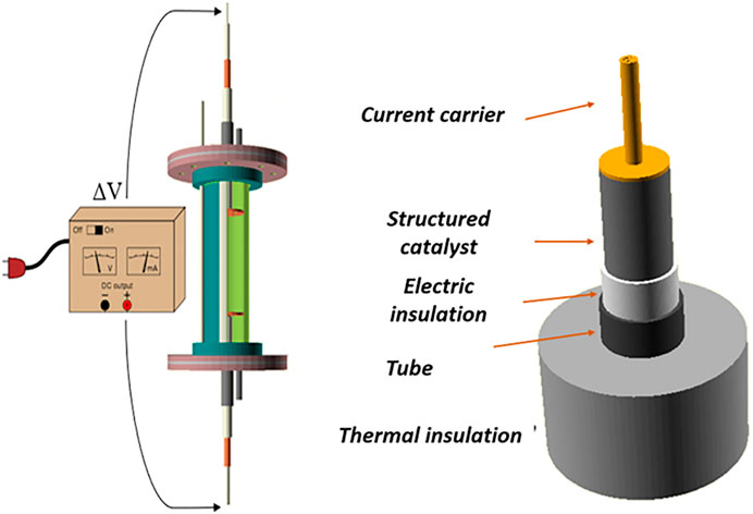
FIGURE 1. Sketch of the reactor considered for the numerical modelling.
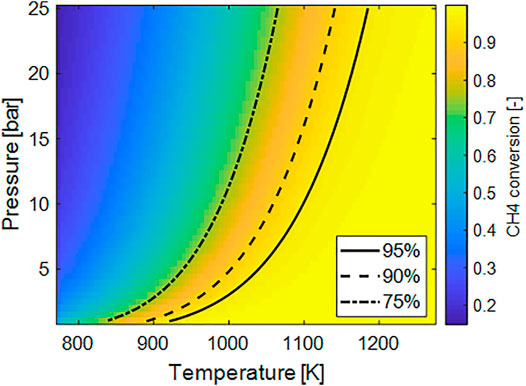
FIGURE 2. Plot of the equilibrium methane conversion as a function of temperature and pressure for concentrated stream and S/C = 4.
The specific energy demand (Figure 3A) was computed assuming the equilibrium composition and assuming the feed entering the reactor at T = 500 C. Also in this case the negative effect of the pressure is evident since the minimum of the energy required is found for lower pressure. The increase of the temperature has a maximum-likehood trend on this parameter. To some extent, an increase of the temperature favors the conversion and therefore more hydrogen is present in the feed. On the other hand, by further increasing the temperature the R-WGS reaction is favored, inducing higher heat demand and at the same time decreasing of the H2 fraction in the feed. At low pressure the minimum of the energy is found at lower temperature, where, however the conversion is not adequately high to sustain the process.
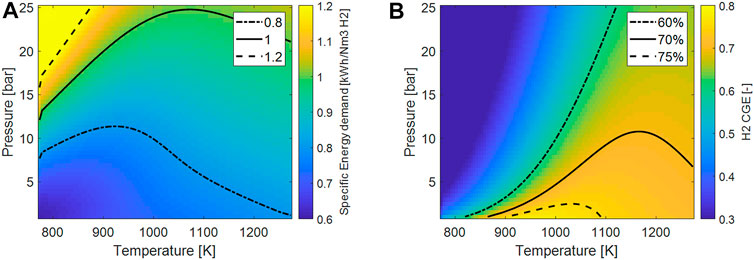
FIGURE 3. (A) Plot of the ideal specific energy consumptions per Nm3 of H2 as a function of process temperature and pressure; (B) plot of the H2 cold-gas efficiency (H2-CGE) as function of process temperature and pressure.
Similar considerations can be drawn considering the H2-CGE. Here, the sensible heat is also considered: on increasing the temperature, a higher fraction of energy is used to heat up the feed and is not actually transformed in chemical energy.
These analyses show how, for a specific H2 production focus, it is appropriate to operate the system at low pressure and in a narrow range of temperatures (900–1100 K). In these conditions, the successful use of Rh-based catalysts has been already demonstrated with respect to conventional catalyst formulations thanks to higher activity and higher resistance to coking. These analyses also set the theoretical limitations of the specific energy consumptions and H2 CGE that will be used in the following sections to evaluate the process performances.
Choice of the Support Material for Electrified Structured Reactors
In order to identify the suitable material for structured reactors/resistances used in the electrified methane steam reforming processes with direct Joule heating, different materials were first considered. Monoliths and open-cell foams are ready-manufactured with different materials, among those some of them are well known for their thermal and electrical properties and have been successfully applied as catalyst supports for conventional catalytic applications. In particular silicon carbide open-cell foams and honeycombs have been already employed in catalytic processes (Quintanilla et al., 2018; Ricca et al., 2019), as well as stainless steel foams and honeycombs (Pauletto et al., 2020). A different note should be reported for copper: open-cell foams have been successfully manufactured and tested in similar applications (Balzarotti et al., 2020), whereas technological limitations are present for copper honeycombs unless very large channel geometries are considered, therefore copper honeycombs were not considered in this work.
To understand the impact of the electrical conductivity, open-cell foams with a porosity ε = 0.9 and honeycombs with Open Frontal Area (OFA) equal to 0.8 are considered. Other geometrical parameters like the cell diameter do not affect the electrical conductivity of the substrate and therefore were not considered at this stage.
The geometrical properties of the supports considered are reported in Table 1. The necessity of an axial continuity limits the length of the reactor considered to 0.2 m, therefore to increase the productivity, a solution with multiple units operating in parallel will be required. A specific thermal power
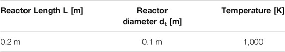
TABLE 1. Dimensions and operative conditions for the evaluations of current, voltage and resistivity in section Choice of the Support Material for Electrified Structured Reactors
Electrical resistivities of the bulk materials considered are reported in Table 2. While for copper and stainless steel the values reported by different references are quite similar (Douglas, 1995), Silicon Carbide exhbits extremely large variations in its electric conductivity as a function of doping species. Therefore, a commercial open-cell foam support in SiC, purchased from Erbicol, was tested in-house to determine the law of resistivity against temperature, by applying DC current with a STAMOS S-LS-76 Laboratory Power Supply to a resistance with L = 0.1 m and dt = 0.03 m that was thermally insulated with a layer of quartz-wool. From the measured resistance, first the resistivity of the structured reactor was calculated and then the bulk resistivity was calculated by using the inverse of Eq. (15).
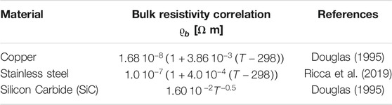
TABLE 2. Electrical resistivity of considered materials.
The resistivity of the metals are several order of magnitude lower than the one of SiC and increase with temperature, whereas in the case of SiC the resistivity has a strong drop at low temperature, whereas it is almost constant at high temperature. Values are reported in Table 2.
In Table 3, the electric parameters of the structures needed to provide a thermal power density of 10 MW/m3 are reported. This value of thermal power density can be taken as a reference for intensified processes since it is well above the industrial thermal duty of reforming applications (Wismann et al., 2019a; Wismann et al., 2019b). Due to the extremely different electrical properties of the materials, very different currents/voltages are required to provide the required power density to the systems.
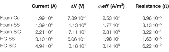
TABLE 3. Electrical parameters of different structured reactors to provide a power density of 10 MW/m3.
In particular, in the case of metallic supports, very high currents (and very low ΔV) are expected, whereas for SiC more reasonable values are found. For their geometrical features and for technological limitations in terms of solid fraction, the effective resistivity of monoliths is 5 times lower than the one of foams made of the same material, therefore they display higher currents and lower ΔV. Typically, to reduce the power loss in conductors, it is necessary to operate at high voltages and low currents, therefore the solution based on SiC can be preferred for this application. Literature studies report a possible large variability of SiC resistivity. However, given these results, materials that display resistivity almost in the same order of magnitude tha SiC, and a similar temperature/chemical resistance can be considered for this application.
Moreover, the effective current density (calculated as
Simulation of an Adiabatic e-MSR Unit
Honeycomb Monoliths
The effect of the space velocity (GHSV) and of the electric current supplied to the system was investigated by simulating a honeycomb monolith with 200 CPSI and a catalyst loading of 100 g/lit. The operative conditions are listed in detail in Table 4.
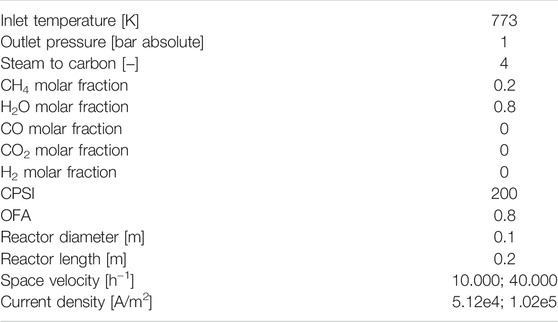
TABLE 4. Operative conditions for simulations in section with Honeycomb Monoliths an Adiabatic e-MSR Unit.
Two conditions were considered, the former with a space velocity of 10,000 h−1 and the second one with a GHSV of 40,000 h−1. The current density was determined as follows. On the basis of the space velocity, the thermal power needed to bring the system at themodynamic equilibrium and an outlet temperature of 1073 K was calculated. Once known the volume of the reactor, the value of QJoule can be easily determined. Then, an average value of resistivity for the foam was assumed (taken at T = 923 K) and the current density is determined. Finally, it was checked that the non-constant resistivity along the reactor axis does not lead to strong variations with respect to the desired behavior.
On comparing the two temperature profiles in Figures 4A,B), it can be noticed that in the case of low space velocity the temperature profile has an almost constant slope in the upstream region and then starts to grow more rapidly towards the end of the reactor, where the methane is almost completely converted, while at higher space velocity the distinction is less pronounced since the conversion of methane is more gradual along the reactor length. In this case, also, some gas-solid temperature gradients are evident, due to the high power transferred between the two phases. Due to the presence of a positive heat input, the solid at the entrance of the reactor is hotter than the gas temperature, The same is evident at the oultet of the reactor.
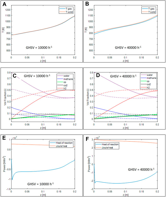
FIGURE 4. Simulations of 200 CPSI OFA 0.8 monoliths with conditions reported in Table 4. Axial temperature profiles for GHSV = 10.000 h−1 (A) and 40.000 h−1 (B), volumetric fraction axial profile for GHSV = 10.000 h−1 (C) and 40.000 h−1 (D), thermal power generated and required by the reaction for GHSV = 10.000 h−1 (E) and 40.000 h−1 (F).
By looking at the volume fractions and at the equilibrium compositions evaluated at the local temperatures, Figures 4C,D), it can be appreciated that at low space velocity the system is able to reach the thermodynamic equilibrium close to the end of the reactor, whereas, at higher space velocity the system is not able to reach this condition. Looking at the local heat demand - Figures 4E,F) - this is even more evident: at low space velocity, after a sharp peak at the reactor inlet, the power demand is almost constant, while it rapidly decreases as the system approaches the equilibrium. In the case of higher space velocity, instead, more uneven profiles are present, due to the complex coupling between kinetics and temperatures. After a sharp peak due to entrance conditions where the reaction rate is maximum, the demand remains stable due to a combination of an increase of the local temperature that boost the reaction rate and the decrease of the reactants that occurs along the reaction axis. Finally, the demand start to decrease towards the end of the reactor because the system get closer to thermodynamic conditions. The heat generated by the Joule effect, instead, follows the temperature curve and decreases towards the end of the reactor with a small slope.
The effect of changing the space velocity and the inlet current is further illustratated in Figure 5A), where, the methane conversion, the H2 CGE and the outlet solid temperature are plotted as a function of the space velocity. The same reactor geometry illustrated in Table 4 were employed as well as the feed composition. The inlet current was varied with the space velocity in order to increase linearly the power with the GHSV (assuming a negligible effect of the temperature on the resistivity, QJoule ∼
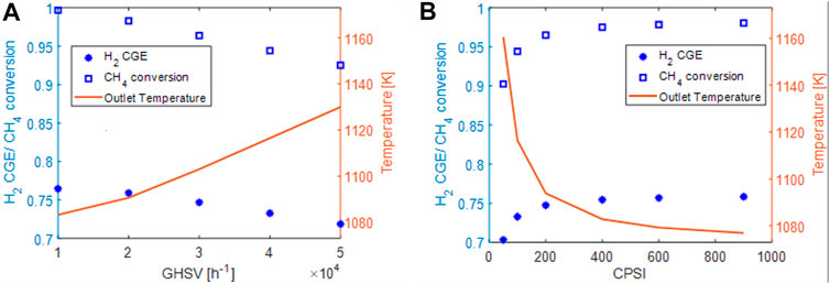
FIGURE 5. (A) effect of space velocity on conversion (blue squares), Hydrogen cold gas efficiency (blue asterisks) and outlet solid temperature (red line). (B) effect of the CPSI on conversion (blue squares), Hydrogen cold gas efficiency (blue asterisks) and outlet solid temperature (red line).
On increasing the space velocity, we note a systematic decrease of the methane conversion (from 99.7% at GHSV = 10,000 h−1 to 92% at GHSV = 50,000 h−1) and accordingly a reduction of the quota of the electric power converted in hydrogen chemical energy (i.e. reduction of H2-CGE). At the same time, the reduction of the methane conversion causes an increase of the outlet temperature.
In Figure 5B), the performances of the system at GHSV of 40.000 h−1 were investigated at fixed catalyst inventory by changing the cell density (CPSI) of the honeycomb. The same reactor geometry and feed composition were considered. By increasing the CPSI of the honeycomb (again, at almost fixed thermal power provided), an increase of the conversion, of the H2 production is observed at the expenses of the outlet solid temperature. This can be associated with the presence of either internal or external mass transport resistances that limit methane conversion but are reduced when using honeycomb supports with an higher CPSI.
To understand the impact of internal and external mass transport limitations, which may become a factor in designing electrified steam reforming reactors with intensified heat transfer properties, the effectiveness factor, evaluated for a slab-geometry and assuming pseudo-first order MSR reaction and the Damköhler number (Da) were calculated at initial conditions and at assigned temperature as a function of the catalyst inventory and of the CPSI:
In the case of monoliths, both the terms apperaring in the Da expression are weakly affected by the space velocity (poor dependency on kv) while the effectiveness factor does not depend on the space velocity as well. A space velocity of 40.000 h−1 was considered. As clearly seen from the heat of reaction in Figures 4E,F), at inlet conditions the reaction rate is maximum, therefore this is a conservative choice. However, these analyses can be used for design purposes and identify optimal catalyst loading and honeycomb shape. Two temperature levels were chosen for this analysis, 873 and 1073 K as representative of intermediate and high temperatures. In the figure, the Damköhler number and the effectiveness factor refered to the methane steam reforming reaction are charted againts the CPSI and the catalyst inventory. To exploit the catalyst loaded in the system, the effectiveness factor should be maximized and the Da number should be minimized. It can be observed that at the increase of CPSI for fixed catalyst amount the limitations are reduced, due to an increase of the surface area of the support. For the same reason, by increasing the catalyst loading the limitation increase since the rate of chemical reaction is boosted by an increase of the catalyst mass.
Clearly, by increasing the temperature the rate of reaction increases, therefore the diffusional limitations become more severe. The process, especially at high temperature is controlled by both internal and external mass transfer limitations. However, by looking at the computed values of Da and catalyst effectiveness reported in Figure 6, internal resistances can be kept under control even at high temperature by choosing the proper support geometry (as also documented by Figure 5B), but the external mass transport limitations remain the bottleneck of the process, in line with reports by Wismann et al. (2019b) and by Italiano et al. (2018).
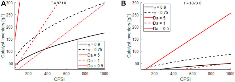
FIGURE 6. impact of external and internal mass transfer limitations on design parameters of honeycomb structures at GHSV = 40.000 h−1: (A) considerations for S/C = 4 and T = 873 K, p = 1 atm, (B) considerations for S/C = 4 and T = 1073 K, p = 1 atm.
Open-Cell Foams
Open cell foams are regarded as interesting catalyst supports for their potential of reducing external mass transport limitations thanks to their tortuous geometry (Bracconi et al., 2018). Therefore, they were considered as an alternative catalyst substrate also for this application. First, a foam with a cell size equal to 2 mm, an open porosity equal to 0.9 and a catalyst inventory of 100 g/L was considered. Also in this case, preliminary simulations were performed for a case of low GHSV (10.000 h−1) and high GHSV (40.000 h−1) with input currents of 2.27 × 10⁴ and 4.59 × 10⁴ (A/m2) respectively. In the case of foams the current is lower than in monoliths to compensate the higher resistivity due to the greater solid fraction and tortuosity. All the conditions considered are listed in Table 5.
TABLE 5. Operative conditions for simulations in section with Open cell foams a Non-Adiabatic e-MSR Unit.
While the shape of temperature profiles (Figures 7A,B) is similar to the case of honeycombs, it is evident how, for the same volumetric heat demand, open-cell foams promote the gas/solid heat transfer, thus limiting the temperature gradients between the two phases. Looking at the profiles of species mole fractions - Figures 7C,D), they approach thermodynamic equilibrium earlier than in the analogous simulations performed for the honeycomb monolith. An increase of the apparent reaction rate can be noticed by comparing the heat of reaction profiles, Figure 7 E-F to those simulated for the honeycomb monoliths.
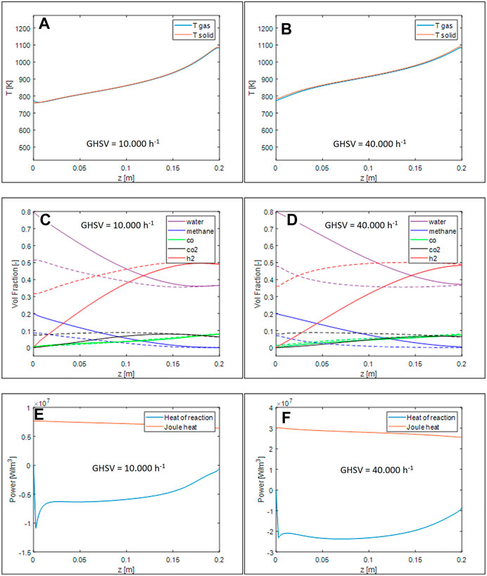
FIGURE 7. Axial temperature profiles for GHSV = 10.000 h−1 (A) and 40.000 h−1 (B), volumetric fraction axial profile for GHSV = 10.000 h−1 (C) and 40.000 h−1 (D), thermal power generated and required by the reaction for GHSV = 10.000 h−1 (E) and 40.000 h−1 (F).
To understand the impact of the operative conditions and of the geometrical properties of the support, we analyzed the effect of an increase of the space velocity for the foam used also for Figure 7 and the variation of the cell size at GHSV = 40.000 h−1. Results are plotted in Figures 8A,B, respectively. The same reactor geometry and steam to carbon ratio listed in Table 5 were considered. As before, the current for each simulations was set to keep the ratio power/space velocity almost constant and equal to the one used for honeycombs.
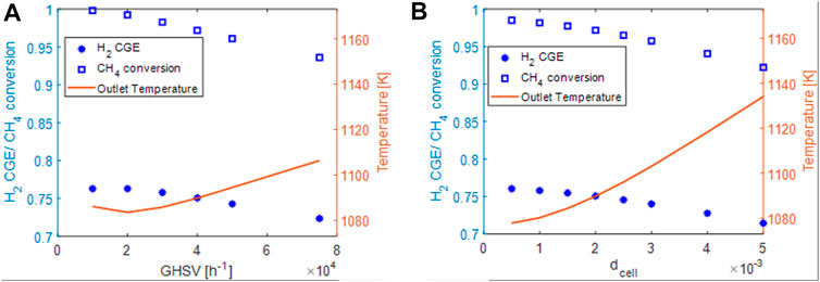
FIGURE 8. (A) effect of space velocity on conversion (blue squares), Hydrogen cold gas efficiency (blue asterisks) and outlet solid temperature (red line). (B) effect of the CPSI on conversion (blue squares), Hydrogen cold gas efficiency (blue asterisks) and outlet solid temperature (red line).
Like in the case of honeycombs, by increasing the space velocity, a decrement of the conversion and the H2-CGE is observed. However, the methane conversions at the same space velocity are higher than the ones of honeycombs despite a lower surface area (lower catalyst effectiveness) as reported in Table 6.
TABLE 6. Comparison of methane conversion and outlet gas temperature for the honeycomb considered in Figure 4, Figure 5A and the foam considered in Figure 7 and Figure 8A.
The differences reported in conversion appear small, however, assuming that the process is controlled by a pseudo-first order reaction rate (as the employed kinetics and the external mass transfer rate), the difference is in the range of 30–40% and widens by increasing the flow rate. This is consistent with an increase of the volumetric mass transfer coefficient that strongly limits the performances of honeycombs. The solid temperatures reported are also lower than the ones of the honeycombs. This is an effect of the higher effective reaction rate but also of the higher volumetric heat transfer coefficient. As a drawback, on the other hand, open-cell foams exhibit higher pressure drops with respect to honeycomb monoliths. However, for the considered case, even at a GHSVof 75.000 h−1 the pressure drops are well below 0.1 bar in the case of dcell = 2 mm.
The same analysis performed for honeycombs were repeated for open-cell foams considering a cell diameter span of 0.005–0.0005 mm, in the range of commercially available supports. The conversion is enhanced by decreasing the cell size, as expected in internal/external diffusion limited regimes. With the best-available open-cell foams it is possible to reach 98.5% conversion at GHSV = 40.000 h−1 whereas with honeycombs only 97% can be reached.
To understand also in the case of open-cell foams the impact of the limitations, the effectiveness factor and the Da number were evaluated as a function of the cell size and catalyst inventory with the same expresions reported for honeycomb monoliths. Differently from honeycombs, where the mass transport properties are a weak function of the fluid velocity, open-cell foams present a flow-dependent gas/solid mass transport. Therefore, for these simulations a velocity equal to 5 m/s was assumed that corresponds to the conditions of GHSV = 40.000 h−1 for the considered reactor length.
In the case of open cell foams, the limitations become more severe at the increase of the cell size, that is inversely proportional with the surface to volume of the support.
From the results in Figure 9, it is evident how open-cell foams can help in decreasing the external mass transfer limitations: in facts, a very large region of the diagram is characterized by Da < 0.5 for T = 873 K and for Da < 1 for T = 1073 K. On the other hand, surface areas of open cell foams are lower than the ones of honeycomb monoliths and this impacts adversely the internal mass transport resistances.
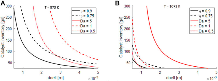
FIGURE 9. Impact of external and internal mass transfer limitations on design parameters of open-cell foams at GHSV = 40.000 h−1: (A) considerations for S/C = 4 and T = 873 K, p = 1 atm, (B) considerations for S/C = 4 and T = 1073 K, p = 1 atm.
Based on these results, we can state that open-cell foams are the best support for electrified MSR thanks to their superior external mass transfer properties.
Analysis of a Non-adiabatic e-MSR Unit
Effect of the Insulation Thickness
Simulation results presented in sections Choice of the Support Material for Electrified Structured Reactors and Simulation of an Adiabatic e-MSR Unit consider an unitary thermal efficiency, assuming no heat dissipation from the reactor to the environment. However, this does not represent a real unit, where the thermal efficiency should be maximized. To understand the impact of thermal dissipations, in this section we consider a non-adiabatic e-MSR reactor based on open-cell foams and we analyze the impact of heat losses on the performances.
First, we analyzed the methane conversion and the outlet temperature for the same foam and same operative conditions reported in Table 4, but this time considering a non adiabatic unit with an insulation of glass wool 1 cm thick. Additionally, the thermal efficiency was computed as reported in Eq. (31).
As apparent from Figure 10, both the methane conversion and the outlet temperature decrease in the case of the insulated unit with respect to the adiabatic one. The relative difference increases at the decrease of the flow rate. The thermal efficiency for such a unit is anyhow quite high, ranging from 97% computed at GHSV = 10.000 h−1 to almost 100% at 40.000 h−1. The effect with respect to the flow rate is consistent with typical observations in quasi-adiabatic units, where the impact of heat losses is reduced by increasing flow rate since the heat losses are almost constant with the flow rate and are a sole function of the temperarure and the reactor/internal geometry.
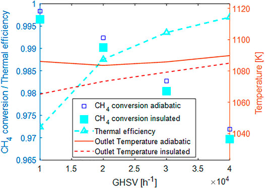
FIGURE 10. Effect of 1 cm thermal insulation layer on the process performances:blue squares CH4 conversion in the adiabatic unit, cyan squares CH4 conversion in insulated unit, cyan triangles thermal efficiency, solid line outlet temperature adiabatic, dashed line outlet temperature insulated.
Effect of the Tube Diameter
In the case of adiabatic units, the performances are independent of the reactor diameter. Instead, in the case of insulated units with heat losses, the heat flux at the wall leads to the development of a radial temperature profile, that is affected by the tube diameter size. Moreover, the specific heat exchange area and the insulation properties are a function of the reactor diameter, too. Therefore, we tried to elucidate the impact of the tube diameter on the temperature profiles and on the performances of the system in the case of an insulation of 2.5 cm of rock wool. A 2D map of the temperature and of the hydrogen volumetric fraction was extracted from the simulations performed at GHSV = 10.000 h−1 for a tube with diameters equal to 2.5 and 10 cm respectively and plotted in Figure 11 against the dimensionless axial and radial coordinates Z* and r*.
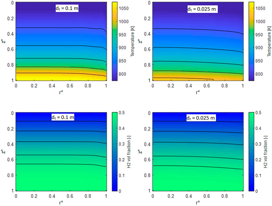
FIGURE 11. 2D temperature maps for a reformer operated at GHSV = 10.000 h−1 and with a diameter of 10 cm (A), 2.5 cm (B). 2D H2 volumetric fraction for a reactor with dt = 10 cm (C) and 2.5 cm (D).
On the left, the results relative to the case of dt = 10 cm are reported, whereas results for dt = 2.5 cm are displayed on the right. From the analysis of the temperature map both by looking at the isolines and the color-map, the different impact of heat losses in the two cases is clearly apparent. In particular, the system with larger reactor diameter reaches higher temperatures, due to the lower impact of thermal dissipation, being the outlet temperature almost 50 °C higher than the case with dt = 2.5 cm. Also, the temperature profile is quite flat, with a gradient localized only close to the reactor walls. Due to the lower thermal efficiency, in the case of the smaller diameter, instead, the temperatures are lower and the profile is more gradual. H2 volume fractions follow the same trend: in the case of the 10 cm reactor, the profiles are more pronounced towards the wall and the system reaches earlier the plateau value, whereas in the case of the smaller diameter reactor the profile is less flat.
Finally, we tried to combine the effects of the reactor diameter and the operative conditions in Figure 12, plotting both the methane conversion and the thermal efficiency when varying the space velocity and tube diameter, considering again an insulation made with 2.5 cm of rock wool.
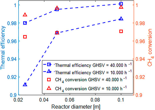
FIGURE 12. Evaluation of methane conversion and thermal efficiency as a function of the space velocity and tube diameter.
Clearly, the difference in methane conversion is quite small when moving from a reactor with 2.5–10 cm tubes both in the case of low and high space velocity. However, the impact on the thermal efficiency is non-negligible. At low space velocity, the drop is almost of 10% when moving from 10 to 2.5 cm, whereas at high space velocity, due to the higher flowing thermal mass the effect is quite small. It worth to emphasize that in this work only external heat dissipations were considered. Other sources of heat dissipation in this system, herein neglected, may include the heat genenerated at the connection between the structured catalyst and the electric sockets.
Discussion
In this work, we have systematically investigated numerically for the first time practical aspects for the design and operation of electrically (Joule) heated methane steam reforming (e-MSR) reactors that use structured catalysts as internal heating elements.
If the objective of the process is the production of clean hydrogen, the process should be run at atmospheric pressure and in a narrow range of temperatures (900–1100 K) to maximize the conversion and the energy efficiency. Moreover, the quota of electric energy that can be transferred in chemical energy is maximixed.
The electrical properties of the bulk material adopted for the manufacturing of the structured catalyst are of paramount importance in order to provide the required amount of heat and at the same time operating the reactor with reasonable values of current and voltage. Based on our analysis, SiC is the best option among the most common materials for the manufacturing of catalyst supports since it helps in designing units that can be run at current and voltages that can be safely employed. Instead, metallic materials require the use, for units with tube diameters in the range of few centimeters of significantly higher current densities and applications at very low voltages.
Mathematical models of the reactors considering two classes of structured catalysts, open-cell foams and honeycombs, coated with a Rh-based catalyst, were developed in Matlab to assess the performances of these reactor units and understand an optimal reactor design. Our modelling analysis shows that the process is under mass transfer control even with modest catalyst inventories, thanks to the high activity of the catalyst. In the reactor, a temperature profile develops along the axial direction of the system as a function of the space velocity. The consumption of the species is concentrated at the inlet of the reactor and, depending on the conditions the system may reach the thermodynamic equilibrium. The proposed solution is able to operate already at the considered scale in much more severe conditions (3–4 times higher GHSV) than industrial reforming units, thanks to a very effective catalyst, a substrates that promotes mass transfer and the possibility of generating evenly distributed high heat fluxes.
Open-cell foams and monoliths were analyzed to understand the impact of the structure choice on the reactor performances Due to their higher surface area, honeycombs can offer lower internal mass transport resistances but also show a significantly worse volumetric mass transfer. Based on these considerations, we think that open-cell foams are the best option for running e-MSR over washcoated structured catalysts. The present solution is actually under testing in the group of Catalysis and Catalytic Processes at Politecnico di Milano, providing promising results in terms of process intensification potential.
Finally the analysis of the impact of heat losses on the process performances indicates that a proper thermal insulation of the system is required, especially at the smallest scales. The temperature profiles in these systems in the radial direction are almost flat also in the case of non-adiabatic units. The thermal performances of the system improve at the increase of the space velocity at which the system is operated and increase at the increase of the reactor diameter, giving few insights on the possible structured catalyst geometry and operative conditions.
Data Availability Statement
The raw data supporting the conclusions of this article will be made available by the authors, without undue reservation.
Author Contributions
MA: Conceptualization, Numerical Modelling, Writing Original Draft AB: Conceptualization, Writing Revision and Editing GG: Conceptualization, Writing Revision and Editing ET: Conceptualization, Writing Revision and Editing, Funding Acquisition.
Funding
The research leading to these results has received funding from the European Research Council (ERC) under the European Union’s Horizon 2020 Research and Innovation Program (Grant Agreement no. 694910/INTENT).
Conflict of Interest
The authors declare that the research was conducted in the absence of any commercial or financial relationships that could be construed as a potential conflict of interest.
Publisher’s Note
All claims expressed in this article are solely those of the authors and do not necessarily represent those of their affiliated organizations, or those of the publisher, the editors and the reviewers. Any product that may be evaluated in this article, or claim that may be made by its manufacturer, is not guaranteed or endorsed by the publisher.
References
Aghaei, P., Visconti, C. G., Groppi, G., and Tronconi, E. (2017). Development of a Heat Transport Model for Open-Cell Metal Foams with High Cell Densities. Chem. Eng. J. 321, 432–446. doi:10.1016/J.CEJ.2017.03.112
Ambrosetti, M., Bracconi, M., Groppi, G., and Tronconi, E. (2017). Analytical Geometrical Model of Open Cell Foams with Detailed Description of Strut-Node Intersection. Chem. Ingenieur Technik 89, 915–925. doi:10.1002/cite.201600173
Badakhsh, A., Kwak, Y., Lee, Y.-J., Jeong, H., Kim, Y., Sohn, H., et al. (2021). A Compact Catalytic Foam Reactor for Decomposition of Ammonia by the Joule-Heating Mechanism. Chem. Eng. J. 426, 130802. doi:10.1016/j.cej.2021.130802
Bakhtyari, A., Makarem, M. A., and Rahimpour, M. R., Hydrogen Production through Pyrolysis, Encyclopedia of Sustainability Science and Technology (2019), R. A. Meyers (ed.). doi:10.1007/978-1-4939-7789-5
Balzarotti, R., Ambrosetti, M., Beretta, A., Groppi, G., and Tronconi, E. (2020). Investigation of Packed Conductive Foams as a Novel Reactor Configuration for Methane Steam Reforming. Chem. Eng. J. 391, 123494. doi:10.1016/j.cej.2019.123494
Balzarotti, R., Beretta, A., Groppi, G., and Tronconi, E. (2019). A Comparison between Washcoated and Packed Copper Foams for the Intensification of Methane Steam Reforming. React. Chem. Eng. 4, 1387–1392. doi:10.1039/c9re00125e
Bracconi, M., Ambrosetti, M., Maestri, M., Groppi, G., and Tronconi, E. (2018). A Fundamental Investigation of Gas/solid Mass Transfer in Open-Cell Foams Using a Combined Experimental and CFD Approach. Chem. Eng. J. 352, 558–571. doi:10.1016/j.cej.2018.07.023
Bracconi, M., Ambrosetti, M., Maestri, M., Groppi, G., and Tronconi, E. (2020). Analysis of the Effective thermal Conductivity of Isotropic and Anisotropic Periodic Open Cellular Structures for the Intensification of Catalytic Processes. Chem. Eng. Process. - Process Intensification 158, 108169. doi:10.1016/j.cep.2020.108169
Bracconi, M., Ambrosetti, M., Okafor, O., Sans, V., Zhang, X., Ou, X., et al. (2019). Investigation of Pressure Drop in 3D Replicated Open-Cell Foams: Coupling CFD with Experimental Data on Additively Manufactured Foams. Chem. Eng. J. 377, 120123. doi:10.1016/j.cej.2018.10.060
Centi, G., and Perathoner, S. (2021). Redesign Chemical Processes to Substitute the Use of Fossil Fuels: A Viewpoint of the Implications on Catalysis. Catal. Today. doi:10.1016/j.cattod.2021.03.007
Choi, I.-H., Seo, M. W., Ra, H. W., Lee, K.-Y., and Hwang, K.-R. (2021). Advanced Approach for Catalytic Decomposition of Tar: Electrically Heated Catalyst System. Chem. Eng. Process. - Process Intensification 165, 108407. doi:10.1016/j.cep.2021.108407
Colbertaldo, P., Guandalini, G., and Campanari, S. (2018). Modelling the Integrated Power and Transport Energy System: The Role of Power-To-Gas and Hydrogen in Long-Term Scenarios for Italy. Energy 154, 592–601. doi:10.1016/j.energy.2018.04.089
Christy, E. J. S., and Pius, A. (2021). Performance of Metal Free g-C3N4 Reinforced Graphene Oxide Bio-Composite for the Removal of Persistent Dyes. Environ. Toxicol. Chem. 3, 220–233. doi:10.1016/j.cattod.2021.06.003
de Dios García, I., Stankiewicz, A., and Nigar, H. (2021). Syngas Production via Microwave-Assisted Dry Reforming of Methane. Catal. Today 362, 72–80. doi:10.1016/j.cattod.2020.04.045
Della Torre, A., Montenegro, G., Onorati, A., and Cerri, T. (2018). CFD Investigation of the Impact of Electrical Heating on the Light-Off of a Diesel Oxidation Catalyst. SAE Tech. Pap., 1–14. doi:10.4271/2018-01-0961
Dinh, D. K., Trenchev, G., Lee, D. H., and Bogaerts, A. (2020). Arc Plasma Reactor Modification for Enhancing Performance of Dry Reforming of Methane. J. CO2 Utilization 42, 101352. doi:10.1016/j.jcou.2020.101352
Dixon, A. G., and Partopour, B. (2020). Computational Fluid Dynamics for Fixed Bed Reactor Design. Annu. Rev. Chem. Biomol. Eng. 11, 109–130. doi:10.1146/annurev-chembioeng-092319-075328
Donazzi, A., Beretta, A., Groppi, G., and Forzatti, P. (2008). Catalytic Partial Oxidation of Methane over a 4% Rh/α-Al2O3 Catalyst. Part I: Kinetic Study in Annular Reactor. J. Catal. 255, 241–258. doi:10.1016/j.jcat.2008.02.009
Dou, L., Yan, C., Zhong, L., Zhang, D., Zhang, J., Li, X., et al. (2020). Enhancing CO2 Methanation over a Metal Foam Structured Catalyst by Electric Internal Heating. Chem. Commun. 56, 205–208. doi:10.1039/c9cc07525a
Glicksman, L. R. (1994). “Heat Transfer in Foams,” in Low Density Cellular Plastics. Editors N. C. Hilyard, and A. Cunningham 1st ed. (Springer Netherlands), 369. doi:10.1007/978-94-011-1256-7_5
Italiano, C., Ashraf, M. A., Pino, L., Quintero, C. W. M., Specchia, S., and Vita, A. (2018). Rh/CeO2 Thin Catalytic Layer Deposition on Alumina Foams: Catalytic Performance and Controlling Regimes in Biogas Reforming Processes. Catalysts 8, 448–525. doi:10.3390/catal8100448
Layritz, L. S., Dolganova, I., Finkbeiner, M., Luderer, G., Penteado, A. T., Ueckerdt, F., et al. (2021). The Potential of Direct Steam Cracker Electrification and Carbon Capture & Utilization via Oxidative Coupling of Methane as Decarbonization Strategies for Ethylene Production. Appl. Energ. 296, 117049. doi:10.1016/j.apenergy.2021.117049
Lemlich, R. (1978). A Theory for the Limiting Conductivity of Polyhedral Foam at Low Density. J. Colloid Interf. Sci. 64, 107–110. doi:10.1016/0021-9797(78)90339-9
Mortensen, P. M., Bendixen, F. B., Valler, P., and Sorea, A. (2019). WO2019228795 - Catalyst and System FOR METHANE STEAM REFORMING BY RESISTANCE HEATING. SAID CATALYST'S PREPARATION.
Palma, V., Barba, D., Cortese, M., Martino, M., Renda, S., and Meloni, E. (2020). Microwaves and Heterogeneous Catalysis: A Review on Selected Catalytic Processes. Catalysts 10, 246. doi:10.3390/catal10020246
Pauletto, G., Vaccari, A., Groppi, G., Bricaud, L., Benito, P., Boffito, D. C., et al. (2020). FeCrAl as a Catalyst Support. Chem. Rev. 120, 7516–7550. doi:10.1021/acs.chemrev.0c00149
Pellegrini, L. A., De Guido, G., and Moioli, S. (2020). Design of the CO2 Removal Section for PSA Tail Gas Treatment in a Hydrogen Production Plant. Front. Energ. Res. 8, 1–10. doi:10.3389/fenrg.2020.00077
Pérez-Camacho, M. N., Abu-Dahrieh, J., Rooney, D., and Sun, K. (2015). Biogas Reforming Using Renewable Wind Energy and Induction Heating. Catal. Today 242, 129–138. doi:10.1016/j.cattod.2014.06.010
Peters, R., Baltruweit, M., Grube, T., Samsun, R. C., and Stolten, D. (2019). A Techno Economic Analysis of the Power to Gas Route. J. CO2 Utilization 34, 616–634. doi:10.1016/j.jcou.2019.07.009
Mortensen, P. M., Klein, R., and Aasgren-Petersen, K., US 20210113983 - Endothermic Reactions Heated by Resistance Heating
Quintanilla, A., Casas, J. A., Miranzo, P., Osendi, M. I., and Belmonte, M. (2018). 3D-Printed Fe-Doped Silicon Carbide Monolithic Catalysts for Wet Peroxide Oxidation Processes. Appl. Catal. B: Environ. 235, 246–255. doi:10.1016/j.apcatb.2018.04.066
Renda, S., Cortese, M., Iervolino, G., Martino, M., Meloni, E., and Palma, V. (2020). Electrically Driven SiC-Based Structured Catalysts for Intensified Reforming Processes. Catal. Today. doi:10.1016/j.cattod.2020.11.020
Ricca, A., Truda, L., and Palma, V. (2019). Study of the Role of Chemical Support and Structured Carrier on the CO2 Methanation Reaction. Chem. Eng. J. 377, 120461. doi:10.1016/j.cej.2018.11.159
Rieks, M., Bellinghausen, R., Kockmann, N., and Mleczko, L. (2015). Experimental Study of Methane Dry Reforming in an Electrically Heated Reactor. Int. J. Hydrogen Energ. 40, 15940–15951. doi:10.1016/j.ijhydene.2015.09.113
Roelofsen, O., Somers, K., Speelman, E., and Witteveen, M. (2020). Plugging In : What Electrification Can Do for Industry. McKinsey report.
Rostrup-Nielsen, J. R. (1984). Catalysis Science and Technology Chapter 1 : Catalytic Steam Reforming. 1st edition. Berlin, Belrin: Springer-Verlag.
Scarfiello, C., Bellusci, M., Pilloni, L., Pietrogiacomi, D., La Barbera, A., and Varsano, F. (2021). Supported Catalysts for Induction-Heated Steam Reforming of Methane. Int. J. Hydrogen Energ. 46, 134–145. doi:10.1016/j.ijhydene.2020.09.262
Tamhankar, S. S., Natarajan, R., Krishnamurthy, R., and Mabrouk, R., US20180148330 - METHODS FOR STEAM METHANE REFORMING
Thema, M., Bauer, F., and Sterner, M. (2019). Power-to-Gas: Electrolysis and Methanation Status Review. Renew. Sustainable Energ. Rev. 112, 775–787. doi:10.1016/j.rser.2019.06.030
Tronconi, E., and Forzatti, P. (1992). Adequacy of Lumped Parameter Models for SCR Reactors with Monolith Structure. Aiche J. 38 (2), 201–210. doi:10.1002/aic.690380205
VDI-Gesellschaft Verfahrenstechnik und Chemieingenieurwesen (2010). in VDI Heat Atlas. Second Edition.
Visconti, C. G., Groppi, G., and Tronconi, E. (2013). Accurate Prediction of the Effective Radial Conductivity of Highly Conductive Honeycomb Monoliths with Square Channels. Chem. Eng. J. 223, 224–230. doi:10.1016/j.cej.2013.02.095
Wismann, S. T., Engbæk, J. S., Vendelbo, S. B., Bendixen, F. B., Eriksen, W. L., Aasberg-petersen, K., et al. (2019). Electrified Methane Reforming: A Compact Approach to Greener Industrial Hydrogen Production. Science 364, 759756–759759. doi:10.1126/science.aaw8775
Wismann, S. T., Engbæk, J. S., Vendelbo, S. B., Eriksen, W. L., Frandsen, C., Mortensen, P. M., et al. (2019). Electrified Methane Reforming: Understanding the Dynamic Interplay. Ind. Eng. Chem. Res. 58, 23380–23388. doi:10.1021/acs.iecr.9b04182
Yan, P., Stankiewicz, A. I., Eghbal Sarabi, F., and Nigar, H. (2021). Microwave Heating in Heterogeneous Catalysis: Modelling and Design of Rectangular Traveling-Wave Microwave Reactor. Chem. Eng. Sci. 232, 116383. doi:10.1016/j.ces.2020.116383
NIST-JANAF Thermochemical Tables (2021), NIST-JANAF Thermochemical Tables, https://janaf.nist.gov/ (Accessed May 19, 2021).
Glossary
Subscripts and Superscripts
Keywords: electrification, hydrogen, methane steam reforming, E-MSR, process intensification
Citation: Ambrosetti M, Beretta A, Groppi G and Tronconi E (2021) A Numerical Investigation of Electrically-Heated Methane Steam Reforming Over Structured Catalysts. Front. Chem. Eng. 3:747636. doi: 10.3389/fceng.2021.747636
Received: 26 July 2021; Accepted: 17 September 2021;
Published: 12 October 2021.
Edited by:
Vincenzo Spallina, The University of Manchester, United KingdomReviewed by:
Ali Bakhtyari, Shiraz University, IranEmanuele Moioli, Paul Scherrer Institut, Switzerland
Copyright © 2021 Ambrosetti, Beretta, Groppi and Tronconi. This is an open-access article distributed under the terms of the Creative Commons Attribution License (CC BY). The use, distribution or reproduction in other forums is permitted, provided the original author(s) and the copyright owner(s) are credited and that the original publication in this journal is cited, in accordance with accepted academic practice. No use, distribution or reproduction is permitted which does not comply with these terms.
*Correspondence: Matteo Ambrosetti, bWF0dGVvLmFtYnJvc2V0dGlAcG9saW1pLml0; Enrico Tronconi, ZW5yaWNvLnRyb25jb25pQHBvbGltaS5pdA==