 Osamu Tonomura
 Masaru Noda
- Department of Chemical Engineering, Kyoto University, Kyoto, Japan
In the design of microreactors, the shape as well as the size is an important design factor for achieving high performance. Recent advances in computational fluid dynamics (CFD) enable us to know flow and temperature distributions in microreactors of various shapes and sizes without conducting experiments. However, it is often important to develop a simpler model than CFD to further reduce the computational time required for reactor design with iterative performance evaluations. In this research, a thermal-fluid compartment model-based approach is proposed for basic design of a multichannel microreactor. The proposed approach consists of two parts, i.e., thermal design and fluid design. In the thermal design part, two types of thermal compartments, which are used to discretize a reaction channel surrounded by wall and describe the mass and heat balances over the channel, are developed to optimize the channel shape. In the fluid design part, three types of fluid compartments, which are used to discretize the reactor and describe the mass and pressure balances over the reactor, are introduced to optimize manifold shape. The proposed approach is applied to a design problem and the results show that microchannels and manifolds with varying width are effective in realizing the uniform temperature and flow distributions, respectively. In addition to the proposed design approach, a transfer function-based compartment model is developed to estimate the residence time distribution of fluid in a microreactor without running time-dependent CFD simulation.
Introduction
Extensive studies have been carried out on micro chemical process technologies. In particular, analysis of chemical reactions and transport phenomena in micro-space has been performed energetically (Yao et al., 2015; Lee and Fu, 2017; Shrimal et al., 2020). Increasing the throughput of micro chemical plants can be achieved by parallelizing microreactors and/or microchannels within the microreactor. This numbering-up method ensures that research results carried out in a single microchannel can be directly applied to the design of micro chemical plants. A project on micro chemical process technologies, which was started in 2002 under the supervision of the New Energy and industrial technology Development Organization, NEDO, in Japan, was successfully completed in 2009. One of the remarkable results of the project was that nine micro pilot plants were constructed. The experimental results were reported at the international workshop (Yoshida, 2006). In addition, an important concept of isolation of activation and reaction spaces, which makes it possible to separate the space where the reactive intermediates are generated and the space where the reactions take place and to optimize the operating conditions of these spaces individually, was proposed (Mae, 2007). While expectations are growing that microreactors are used for mass production of chemical materials, it is necessary to develop models for analyzing flow and transport phenomena, optimal design and control methodologies, and sensing and monitoring technologies. The desirable characteristics of microreactors arise from the precise control of temperature, residence time distribution and/or degree of mixing. Thus, the design problem of microdevices usually includes constraints on the temperature profile, residence time distribution, and/or size of segment to be mixed. To satisfy these constraints, the shape of the microreactors must be included in the design variables in addition to the volume of them. However, most microreactors are developed on the basis of engineer’s experience. This study focuses on the systematic design procedures of microreactors, especially multichannel microreactors. The multichannel microreactor is composed of inlet and outlet manifolds and parallelized microchannels. If the flow distribution among the microchannels is not uniform, the product quality may deteriorate (Delsman et al., 2005). The flow equipartition in the microchannels is required in order to get the same residence time, which results in the same conversion and selectivity of reaction products. The flow uniformity among the microchannels depends largely on the shape of manifolds, which are the critical space which fills the role of putting microchannels together (Ehrfeld, et al., 2000).
The manifold shape should be optimally designed by a rational decision-making method based on the model, not by trial and error. Recent advances in computational fluid dynamics (CFD) modeling and simulation enable us precise estimation of flow distributions in a microreactor with various manifold shapes. Therefore, a shape optimization method that combines CFD and the mathematical programming methods can be considered. In such shape optimization, the initial shape is defined and meshes are generated. After a CFD simulation, the performance index is calculated. While the result is not optimal, the design variables which define the shape are updated and meshes are regenerated. The point here is to develop the automatic mesh regeneration system for updated shape. Tonomura et al. (2004) developed the CFD-based automatic shape optimization system for a multichannel microreactor with uniform flow distribution, where the model and mesh generator was integrated with CFD simulator. The proposed system can give rigorous results, but the number of design variables is limited because the gradient of the cost function, that is, the sensitivity, is obtained by repeating CFD simulations while perturbing each design variable. The adjoint variable method may be interesting as one of the ways to solve this problem, since it allows successfully obtaining the gradient of the cost function independently of the number of deign variables (Giles and Pierce, 2000). The pressure drop minimization problem for a single U-shaped microchannel has been solved by the adjoint variable method (Tonomura et al., 2010), but it is unclear whether the adjoint variable method is applicable to complex design problems, such as reactor design problems affected by more factors. As an efficient and realistic design method, it would be better to perform the preliminary design that determines the basic structure or shape of the reactor using a model simpler than CFD, and then perform rigorous optimization by CFD. Commenge et al. (2002) examined the specific features of fluid flow in a microreactor with multiple channels by a simple model based on pressure drop calculations through a resistive network of ducts, which provides rapid calculation of the flow distribution. The same model was applied to recent studies, for example, the design of channel width and triangle manifold that can achieve more uniform velocity distribution (Chao et al., 2020), the design of a plate-type reformer for distributed hydrogen generation to avoid flow maldistribution (Ashraf et al., 2020), the design of a cutting microchannel plate to improve the velocity distribution (Huang et al., 2019), and the design of split-and-recombine-type flow distributors connected to microreactors (Tonomura et al., 2019a; 2019b), where the ducts were referred to as the fluid compartments. While such fluid compartments are useful for predicting flow distributions, it would also be important to develop a compartment model that can predict temperature distributions, which affect reaction performance.
In this study, a thermal compartment model is developed to provide rapid calculation of the temperature distribution in a microreactor. Then, a systematic design approach for microreactors based on thermal-fluid compartment models is proposed. The proposed approach is applied to the optimal shape design problem of a multichannel microreactor with uniform temperature and flow distributions. In addition, a transfer function-based compartment model is developed to estimate the residence time distribution of fluid in a microreactor without running time-dependent CFD simulation.
Compartment model-based reactor shape design
A two-step approach consisting of thermal design and fluid design stages is proposed for the basic design problem of a multichannel microreactor. Each design stage introduces a compartment model and reduces the design’s dependence on CFD. The validity of the proposed approach is assessed through a case study.
Microreactor design problem and design procedure
A multichannel microreactor is typically divided into three sections: inlet manifold section for flow distribution, microchannel section for reaction and outlet manifold section for mixing, as shown in Figure 1. It is possible to control the reaction temperature by sandwiching the reactor between plates where a heat exchange fluid flows. In addition to increasing the number of channels in the reactor, it is possible to increase the production volume by stacking the reactors.
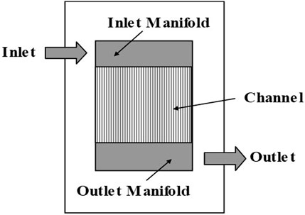
FIGURE 1. A multichannel microreactor.
The design of the microreactor is important for realizing the suitable reaction operation by taking advantage of its excellent characteristics. In the fluid design that controls the flow field, the flow distribution among multiple channels should be controlled, and the use of flow models is useful in predicting it. Although microreactors are known to have high heat transfer performance, it can be compromised by poor design. Therefore, heat transfer models are important in the thermal design that controls the temperature field. When designing a multichannel microreactor, it may be necessary to integrate fluid design and thermal design, but if reaction progress can be neglected in the inlet and outlet manifolds, as is considered in this study, they can be separated into independent optimization problems. Table 1 shows an example of the fluid and thermal design problems of the multichannel microreactor. In the fluid design, manifold shape and number of microchannels are determined to minimize the average residence time of fluid in the microreactor under constraints related to pressure drop, flow distribution and throughput. In the thermal design, the shape of a microchannel and the inlet conditions of reactant and coolant are determined to minimize the temperature distribution in the microreactor under the constraints related to pressure drop and yield or selectivity. In each design problem, a change to a different objective function is possible and the constraint equations are revised as needed.
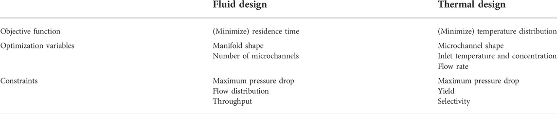
TABLE 1. A design problem of microreactors.
In this study, as shown in Figure 2, a design procedure is proposed in which the basic design by compartment model is performed first, followed by the detailed design by CFD model. The compartment-based basic design is focused on here, because it is an important step that will contribute not only to the derivation of the basic structure or shape of the reactor, but also to the reduction of the computational time required for reactor design with iterative performance evaluations. The compartment-based basic design consists of two parts, i.e., thermal design and fluid design. In the thermal design part, two types of thermal compartments, which are used to discretize a reaction channel surrounded by wall and describe the mass and heat balances over the channel, are developed to optimize the channel shape. In the fluid design part, three types of fluid compartments, which are used to discretize the reactor and describe the mass and pressure balances over the reactor, are introduced to optimize manifold shape. The details of the thermal and fluid compartment models are explained in the following sections.
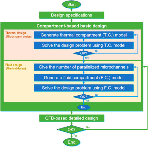
FIGURE 2. Design flowchart.
Thermal compartment model
A thermal compartment model is proposed to provide rapid calculation of the temperature distribution in a microreactor. The basic concept of thermal compartments is the same as that of the fluid compartments, which is explained in the next section. Figure 3 shows the proposed thermal compartment model. When the flow distribution among microchannels is assumed to be uniform, cyclic boundary condition can be applied to one microchannel, which is divided into an adequate number of thermal compartments. There are two types of thermal compartments, namely outer compartments and inner compartments, which describe heat transfer for wall and reaction fluid, respectively. Each compartment has three dimensions (length, depth, and width) and has the mathematical model defined by
where Fi, Ti, Cp and ΔHri are flow rate, temperature, specific heat and reaction heat generated in the compartment i. Qij is heat transfer rate from the thermal compartment i to the surrounding thermal compartment j. Since the ratio of wall volume to channel volume in the microreactor is large, the longitudinal heat conduction inside the wall, which is neglected in the conventional models, is considered in the thermal compartment model. The total heat balance equations of the microchannel is solved to estimate the temperature distribution under given boundary conditions. In the thermal design stage, if the width of each compartment is selected as a design variable, the channel width at the longitudinal position can be optimized by taking into account the constraints related to heat balance, pressure drop, reaction yield/selectivity, temperature, and channel dimensions.
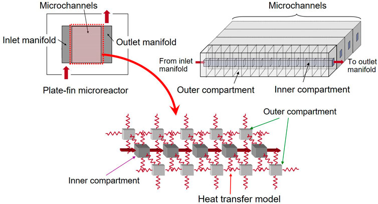
FIGURE 3. Thermal compartment model.
Fluid compartment model
The rigorous fluid dynamics of a microreactor is expressed by Navier-Stokes equations, which are the governing equations of CFD. However, it is often important to develop a simpler model than CFD to further reduce the computational time required for reactor design with iterative performance evaluations. To provide rapid calculation of the flow pattern in a microreactor, a fluid compartment model was reported by Commenge et al. (2002). In this study, the fluid compartment model is introduced. As shown in Figure 4, the multichannel microreactor is divided by fluid compartments. Each fluid compartment has three dimensions (length, depth, and width) and the pressure drop in the fluid compartment is calculated by an equation for estimating the pressure drop of fully-developed laminar flow. Each of microchannels is considered as one compartment, and the inlet and outlet manifolds are divided into as many compartments as the number of microchannels. The compartments assigned to the inlet manifold, outlet manifold, and microchannels are called the distribution, junction, and channel compartments, respectively, which are numbered in order from the upstream side. Figure 4 shows an example of a combination of fluid compartments. While being distributed into each microchannel, the input stream passes through distribution compartments. The partitioned fluid is put together and becomes the output stream, while passing through junction compartments. Pressure balance and mass balance equations are formulated for the combination of fluid compartments. Eq. 2 represents the pressure balance among four compartments shown in Figure 4.
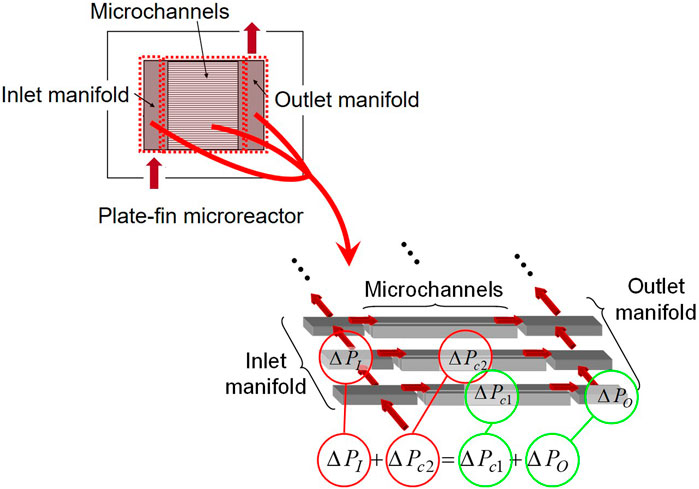
FIGURE 4. Fluid compartment model.
By repeating the derivation of pressure balance and mass balance equations among other sets of compartments, algebraic equations which determine the relation between design parameters and pressure distribution are obtained. The fluid compartment model is useful under laminar flow conditions where the relationship between pressure drop and the flow rate in each channel is linear, and the additional pressure drops at entrance, exit, corner, branching, and merging of channels are negligible. In the fluid design stage, the shapes of the inlet and outlet manifolds and the number of parallel microchannels are determined so as to optimize a given performance index such as the minimization of the total volume in the microreactor. Many constraints related to the pressure and mass balances, flow uniformity, pressure drop, total flow rate and reactor dimensions are considered in this design stage.
Case study
In this case study, Denbigh reactions (Burghardt et al., 1974) shown in Figure 5, which have wide application to a host of real reacting systems, occur in the microchannels. Y is a desired product, X is an intermediate, and P and Q are products of side reactions. All the reaction rate equations are first order and do not involve complex mathematics. The temperature-dependent rate constant
where
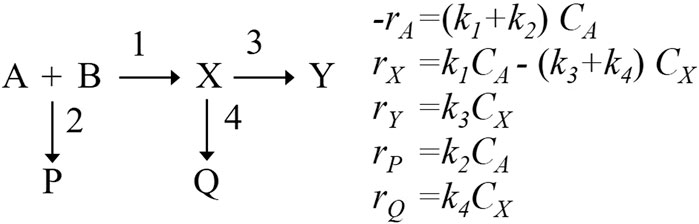
FIGURE 5. Denbigh reactions and their reaction rate equations.
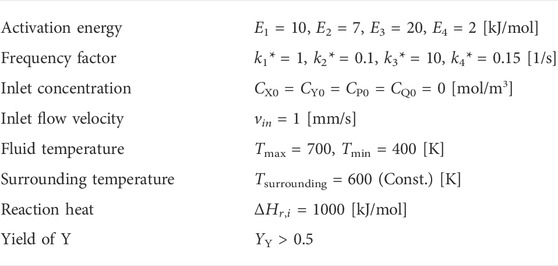
TABLE 2. Design constraints.
In the thermal design, the design region is defined as a rectangular glass whose dimension is 1000 µm in thickness and 1000 µm in width. To calculate the temperature distribution, the design region is divided into 100 inner thermal compartments representing flow in the microchannel and 100 outer thermal compartments representing the wall. These compartments were determined by trial and error, changing the number of compartments until there was little difference in the calculated results of state variables such as temperature inside the reactor. In the optimal design, the width of the microchannel is assumed to be a piecewise linear continuous function that has eleven sections, because unconstrained optimization of all compartments can lead to jagged channel. The objective function of the thermal design problem is to minimize the integral squared temperature error of temperature difference between the fluid temperature and a specified reaction temperature along the microchannel, that is, to uniformize fluid temperature at Tmax, which ensures the maximum yield of the desired product Y. Figure 6 illustrates the thermal design results. The solid line in the top graph corresponds to the optimal channel shape. The microchannel width increases gradually from inlet to outlet. The width near the inlet is narrow due to fast reaction rate. The width of the latter part becomes wider due to slower reaction rate. The dashed line shows the channel width which is optimized as constant value. As shown in the bottom figure, the optimal shape of microchannel is effective in keeping the reaction temperature distribution uniform along the microchannel. On the other hand, the reaction temperature in the conventional straight channel gradually decreases and is close to the surrounding temperature. The composition profiles for the optimal design are shown in Figure 7. The composition of product Y increases monotonically, and that of intermediate X has a maximum. The yields of by-product P for the optimal design (the widening channel) and the conventional design (the straight channel) are 12% and 14%, respectively. The yields of by-product Q for the optimal and conventional designs are 16% and 20%, respectively. Furthermore, the productivity of the optimal design increases by 6%, compared to the conventional design. The effectiveness of the thermal design method is confirmed.

FIGURE 6. Optimal channel width (upper) and temperature profiles (lower).
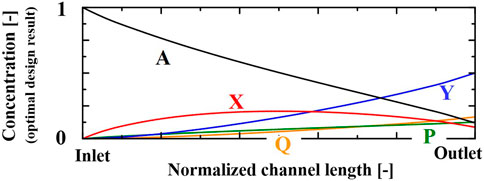
FIGURE 7. Composition profiles in the optimally designed channel.
Subsequent to the thermal design, the fluid design is carried out by using the fluid compartment model, which are explained in Section 3.2. The objective function is to minimize manifold shape, that is, to minimize residence time of fluid in the microreactor. Optimization variable is manifold shape, which is assumed to be trapezium, and the number of microchannels is fixed to be twenty. Constraints are flow uniformity and maximum total pressure drop. Figure 8 (left) shows the normalized flow distribution among the microchannels. The flow velocity of each microchannel normalized by flow velocity averaged by all microchannels. The circles correspond to the optimal design, and the triangles represent the conventional design. The optimal manifold shape, which is shown in Figure 8 (right), enables us to realize the flow equipartition in all microchannels and avoid deterioration in reactor performance.
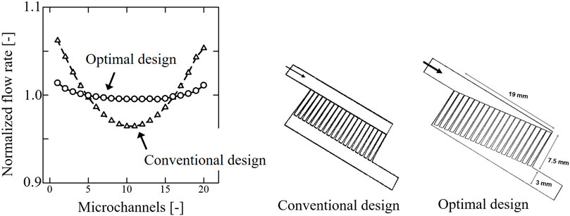
FIGURE 8. Fluid design results: flow uniformity (left) and reactor shape (right).
In the obtained reactor, the following controls are achieved without installing control devices inside the reactor: 1) flow rate of each channel is implicitly controlled by the shape design of the manifolds, 2) temperature and reaction time of reactants are implicitly controlled by the shape design of the microchannels. These show that the mechanisms of controllers are embedded to the reactor as the channel shape and could be called “control by design”. The idea of “control by design” makes it possible to achieve given operating conditions without incorporating a large number of sensors and actuators in a small device.
Compartment model-based RTD calculation
The residence time distribution (RTD) of fluid is one of the key design specifications for microreactors. RTD is measured experimentally by introducing a tracer material into the inflow and measuring its concentration in the outflow. An impulse response or a step response of the tracer concentration is usually measured (Levenspiel, 1958). Recent advances in CFD simulation technologies enable us to estimate the RTD of fluid in devices without performing experiments. However, RTD calculations by CFD require long computational time. In this section, the objective is to develop a simplified calculation method of RTD, without running time-dependent CFD simulations.
Developed compartment model
In the previous section, the mass and pressure balance equations are formulated among compartments to estimate the flow and pressure distribution in the multichannel microreactor. In this section, a transfer function is embedded in each compartment to estimate the RTD where the laminar flow velocity distributions dominate (Hopkins et al., 1969). The tracer concentration at the inlet of a compartment is changed stepwise from zero to
where
Consider a fully-developed fluid flowing at average velocity
Since the maximum velocity at the center is the double of the average velocity,
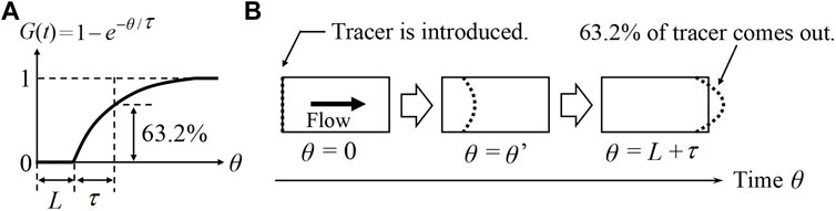
FIGURE 9. (A) Step response curve of
RTD calculation of a multichannel microreactor
The compartment model-based method is applied to RTD calculation of a multichannel microreactor with 10 parallelized microchannels. Figure 10 shows the multichannel microreactor, which is expressed by 10 distribution compartments, 10 channel compartments, and 10 junction compartments. Water (293 K) is fed to the inlet of the reactor at uniform velocity of 1 mm/s. At the outlet, the pressure is specified (atmospheric pressure). In this case study, the average residence time is sufficiently smaller than the time required for diffusion. In other words, the effect of diffusion on RTD is negligible. The flow velocity of each compartment is derived by solving the mass and pressure balance equations among compartments. When calculating the RTD of fluid in the multichannel microreactor, the transfer function model is embedded in each compartment. Three parameters of the transfer function in each compartment are determined from the information concerning the compartment sizes and the average velocity of fluid.
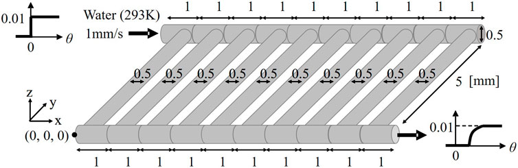
FIGURE 10. Compartmentalized multichannel microdevice.
In this case study, Simulink® is utilized to calculate the RTD of fluid in the multichannel microreactor. Solid line in Figure 11 (left) represents the normalized RTD curve, namely the result of step response estimated by the proposed transfer function-based model. In order to validate this RTD calculation result, time-dependent CFD simulation is carried out by using Fluent® as follows: the fluid flow equations, i.e., the momentum equations of an isothermal laminar flow, and species equations are solved in this study. The fluid flow equations are first solved using a steady state approach. A passive tracer is then introduced with a step change in its concentration in the feed. After this, the species equation is solved as an unsteady simulation. The tracer fluid is treated as a continuum by solving a transport equation for the tracer species. The averaged concentration of the tracer at the outlet is monitored with time to obtain the RTD. The tracer has the same physical properties as water has, and its diffusivity is fixed at zero. Dashed line in Figure 11 (left) represents the dimensionless step response estimated by CFD simulation. The two obtained RTD curves are very close to each other. However, the dead time calculated by CFD simulation is slightly shorter than that by the transfer function-based model. The difference between CFD simulation and the transfer function-based model is caused by the fact that shortcut flow observed at the corners in the microreactor cannot be described in the proposed compartment model as shown in Figure 11 (right). From this reason, it is considered that the rising point of RTD curve estimated by using the compartment model was delayed.
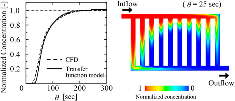
FIGURE 11. RTD curve (left) and contour plot of tracer concentration at z = 250 µm (right).
Conclusion
The performance of a microreactor is greatly influenced by the channel shape as well as the dimensions (volume and length). Therefore, the major feature of the microreactor design problem is that the design variables include variables related to the shape. In this study, a systematic thermal-fluid design approach based on the compartment models was developed. The proposed approach was applied to the shape design problem of a multichannel microreactor with exothermic reactions. The fluid temperature along the microchannel was equalized by changing channel width, that is, by controlling the fluid residence time. The optimally designed manifold shape ensured the same residence time in all parallel microchannels and avoided deterioration in the reactor performance. Since the proposed thermal-fluid compartment model is simple, the computational time of microreactor design can be shortened. It can be concluded that the proposed design approach has the potential for being widely applied to the design problem of microreactors with various constraints. In addition, a transfer function-based compartment model was developed to estimate the residence time distribution of fluid in a microreactor without running time-dependent CFD simulation.
Data availability statement
The raw data supporting the conclusions of this article will be made available by the authors, without undue reservation.
Author contributions
OT, MN and SH contributed to research ideas. OT and MN contributed to modelling, simulation and optimization works. All authors contributed to the article and approved the submitted version.
Funding
This work was partially supported by the Grant-in-Aid for Scientific Research (Nos. 19K05140 and 25220913) and projects, “Development of Microspace and Nanospace Reaction Environment Technology for Functional Materials” and “Development of Continuous Production and Process Technologies of Fine Chemicals,” commissioned by the New Energy and Industrial Technology Development Organization (NEDO) in Japan.
Conflict of interest
The authors declare that the research was conducted in the absence of any commercial or financial relationships that could be construed as a potential conflict of interest.
Publisher’s note
All claims expressed in this article are solely those of the authors and do not necessarily represent those of their affiliated organizations, or those of the publisher, the editors and the reviewers. Any product that may be evaluated in this article, or claim that may be made by its manufacturer, is not guaranteed or endorsed by the publisher.
References
Ashraf, M. A., Tacchino, S., Peela, N. R., Ercolino, G., Gill, K. K., Vlachos, D. G., et al. (2020). Experimental insights into the coupling of methane combustion and steam reforming in a catalytic plate reactor in transient mode. Ind. Eng. Chem. Res. 60 (1), 196–209. doi:10.1021/acs.iecr.0c04837
Burghardt, A., and Skrzypek, J. (1974). Optimal temperature profiles in a tubular reactor for a system of consecutive – competing reactions: A + B → rr + B → S. Chem. Eng. Sci. 29, 1311–1315. doi:10.1016/0009-2509(74)80141-7
Chao, L., Huang, P., and Pan, M. (2020). Reverse optimization algorithm of velocity uniformity in microchannels based on a simplified resistance network model. Chem. Eng. Sci. 221, 115655. doi:10.1016/j.ces.2020.115655
Commenge, J. M., Falk, L., Corriou, J. P., and Matlosz, M. (2002). Optimal design for flow uniformity in microchannel reactors. AIChE J. 48 (2), 345–358. doi:10.1002/aic.690480218
Delsman, E. R., de Croon, M. H. J. M., Elzinga, G. D., Cobden, P., Kramer, G. J., and Schouten, J. C. (2005). The influence of differences between microchannels on micro reactor performance. Chem. Eng. Technol. 28, 367–375. doi:10.1002/ceat.200407126
Ehrfeld, W., Hessel, V., and Löwe, H. “Extending the knowledge base in microfabrication towards chemical engineering and fluid dynamic simulation,” in Proceedings of the 4th International Conference on Microreaction Technology (IMRET 4). Editors W. Ehrfeld, U. Eul, and R.S. Wegeng (Atlanta, USA: AIChE), 3–20.
Giles, M. B., and Pierce, N. A. (2000). An introduction to the adjoint approach to design. Flow. Turbul. Combust. 65, 393–415. doi:10.1023/a:1011430410075
Hopkins, M. J., Sheppard, A. J., and Eisenklam, P. (1969). The use of transfer functions in evaluating residence time distribution curves. Chem. Eng. Sci. 24, 1131–1137. doi:10.1016/0009-2509(69)80083-7
Huang, P., Dong, G., and Pan, M. (2019). The velocity distribution of a cutting microchannel plate based on the resistance network method. Chem. Eng. Sci. 208, 115140. doi:10.1016/j.ces.2019.07.058
Lee, C. Y., and Fu, L. M. (2017). Recent advances and applications of micromixers. Sensors Actuators B Chem. 259, 677–702. doi:10.1016/j.snb.2017.12.034
Levenspiel, O. (1958). Longitudinal mixing of fluids flowing in circular pipes. Ind. Eng. Chem. 50 (3), 343–346. doi:10.1021/ie50579a034
Mae, K. (2007). Advanced chemical processing using microspace. Chem. Eng. Sci. 62, 4842–4851. doi:10.1016/j.ces.2007.01.012
Shrimal, P., Jadeja, G., and Patel, S. (2020). A review on novel methodologies for drug nanoparticle preparation: Microfluidic approach. Chem. Eng. Res. Des. 153, 728–756. doi:10.1016/j.cherd.2019.11.031
Tonomura, O., Kano, M., and Hasebe, S. (2010). Shape optimization of microchannels using CFD and adjoint method. Comput. Aided Chem. Eng. 28 (C), 37–42. doi:10.1016/S1570-7946(10)28007-0
Tonomura, O., Tanaka, S., Noda, M., Kano, M., Hasebe, S., and Hashimoto, I. (2004). CFD-based optimal design of manifold in plate-fin microdevices. Chem. Eng. J. 101 (1-3), 397–402. doi:10.1016/j.cej.2003.10.022
Tonomura, O., Taniguchi, S., Nishi, K., Nagaki, A., Yoshida, J., Hirose, K., et al. (2019a). Blockage detection and diagnosis of externally parallelized monolithic microreactors. Catalysts 9 (4), 308–319. doi:10.3390/catal9040308
Tonomura, O., Taniguchi, S., Hata, K., and Hasebe, S. (2019b). Detection of multiple blockages in parallelized microreactors. Chem. Eng. Technol. 42 (10), 2171–2178. doi:10.1002/ceat.201900146
Yao, X., Zhang, Y., Du, L., Liu, J., and Yao, J. (2015). Review of the applications of microreactors. Renew. Sustain. Energy Rev. 47, 519–539. doi:10.1016/j.rser.2015.03.078
Yoshida, J. (Editor) (2006). Proceedings of the 4th international Workshop on micro chemical plants, Kyoto.
Nomenclature
C concentration [mol/m3]
Cp specific heat [J/kg/K]
E activation energy [J/mol]
F flow rate [g/s]
G transfer function [-]
K steady-state gain [-]
k rate constant [1/s]
k* frequency factor [1/s]
L dead time [s]
LT tube length [m]
Q heat transfer rate [m]
R gas constant [J/kg/K]
r radius [m]
rT tube radius [m]
T temperature [K]
v velocity [m/s]
vmax maximum velocity [m/s]
Y product yield [-]
μ viscosity [m/s]
τ time constant [s]
ΔHr reaction heat [J/mol]
ΔP pressure drop [Pa]
i reaction, compartment number [-]
j compartment number [-]
I inlet manifold [-]
O outlet manifold [-]
c microchannel [-]
0 inlet [-]
Keywords: microreactor, optimal design, shape optimization, compartment modelling, residence time distribution
Citation: Tonomura O, Noda M and Hasebe S (2022) Shape design of channels and manifolds in a multichannel microreactor using thermal-fluid compartment models. Front. Chem. Eng. 4:838336. doi: 10.3389/fceng.2022.838336
Received: 17 December 2021; Accepted: 18 October 2022;
Published: 03 November 2022.
Edited by:
Jean-Marc Commenge, Université de Lorraine, FranceReviewed by:
Yilin Fan, UMR6607 Laboratoire de Thermique et Énergie de Nantes (LTeN), FranceNorbert Kockmann, Technical University Dortmund, Germany
Copyright © 2022 Tonomura, Noda and Hasebe. This is an open-access article distributed under the terms of the Creative Commons Attribution License (CC BY). The use, distribution or reproduction in other forums is permitted, provided the original author(s) and the copyright owner(s) are credited and that the original publication in this journal is cited, in accordance with accepted academic practice. No use, distribution or reproduction is permitted which does not comply with these terms.
*Correspondence: Osamu Tonomura, dG9ub211cmFAY2hlbWUua3lvdG8tdS5hYy5qcA==