- 1Univ. Polytechnique Hauts-de-France, UMR 8201-LAMIH-Laboratoire d’Automatique de Mécanique et d’Informatique Industrielles et Humaines, Valenciennes, France
- 2INSA Hauts-de-France, Valenciennes, France
This paper presents a haptic-based assistance system (AS) for power wheelchair users designed using the model-based shared control approach. The idea is to combine robust control with a high-level driving supervisor in order to successfully share control authority between the wheelchair user and the assistance system. This shared control strategy is composed of two parts, namely an operational part and a tactical part. Through the haptic joystick interface, this assistance system aims to reduce user’s effort when manipulating the joystick, guide the user to avoid any potential collisions, and maintain the active participation of the user in driving the wheelchair. In the operational part, an optimal Takagi-Sugeno fuzzy control approach is proposed to deal with the time-varying user’s intention represented by his desired longitudinal and angular position errors and velocities and hand torques. The control design is formulated as an LMI optimization problem which can be easily solved with numerical solvers. Two unknown input observers for Takagi-Sugeno fuzzy model have been designed to estimate the user’s intention in order to generate an assistance torque via a haptic force feedback joystick. The control supervisor in the tactical part, aims to provide a decision-making signal which allows for the conflict management based on the user hand torque estimation. A specific algorithm has been developed to solve the conflict between the user’s desired actions and the suggestions from the assistance system to ensure the user remains the final decision-maker. Experimental results show the effectiveness and the validity of the proposed assistance system.
1 Introduction
Commercialized since the 1950s (Woods and Watson, 2003), power wheelchairs now play an important role in the daily life of people with limited mobility. Generally, users drive the wheelchair by manipulating a joystick (or other input device) and the controller converts the joystick commands into the voltages applied to the electric motors to move the wheelchair.
1.1 Related studies on power wheelchair assistance system
There is much research on improving user safety and comfort. Wheelchairs can be equipped with many sensors/actuators and different interfaces to increase the situation awareness of users and assist them to avoid any potential accidents or even replace them to perform many different tasks (Simpson, 2009).
Users with severe impairments are often provided with a system that allows them to choose the desired destination/task. The system then performs the latter as an intelligent actuator (Iturrate et al., 2009; Leishman et al., 2010; Carlson and DelMillan, 2013; Carrington et al., 2014; Jain and Argall, 2014). To enhance user comfort during these autonomous navigation tasks, wheelchair acceleration and jerking have been considered in the synthesis of path-following controllers of autonomous wheelchairs (Park and Kuipers, 2011; Morales et al., 2013; Nguyen et al., 2018).
For another group of users with better wheelchair control skills, the authors in Demeester et al. (2010) found that the autonomous functions may be irritating because the assistance is too safe for them. A comprehensive survey in Viswanathan et al. (2017) presents an overall picture of the needs and desires of wheelchair users. The findings suggest that the AS should be customizable to the specific problems of each individual. They also note that users “preferred to drive themselves rather than to be driven” or “preferred the semi-autonomous mode of control over fully autonomous mode, regardless of their cognitive status”. Conflict issues were observed when the user wanted to go “his/her own way” and the AS let them get closer to the obstacles, if necessary. Besides that, users preferred to maintain the wheelchair speed and obtain steering assistance to avoid the obstacles without being stopped. Another suggestion is that the human-machine interaction performed with various feedback interfaces can be employed to increase user situation awareness. However, “communication interfaces must be carefully designed” to reduce user’s workload, as user sensory channels are heavily loaded during the driving task. The study cited above suggests that assistance with both speed and direction may provide users with “a higher level of perceived control of the wheelchair”. These findings confirm the central role of users in designing assistive systems for power wheelchairs where “the most important design aim should be to maximize and augment the skills of the user, not replace them” (Nisbet, 2002).
To satisfy the above-mentioned user preferences, the so-called “shared control” scheme has been proposed. The authors in Vander Poorten et al. (2012) provide the haptic forces for avoiding obstacles using the kinematic properties and the dimensions of the wheelchair. In Devigne et al. (2016), Devigne et al. (2018), the haptic forces are provided thanks to the allowed and forbidden areas in the joystick’s velocity map relating to the obstacles detected. This approach was also extended in Devigne et al. (2019) to assist the wheelchair user in avoiding negative obstacles that occur when the ground drops off and thus evade a falling or tipping hazard for the wheelchair. The number of collisions, the travel time, and the joystick motions were reduced by adapting the Vector Field Histogram method to design the haptic force feedback in Morere et al. (2015).
Combining a standard joystick with a wearable vibrotactile armband device may allow users to overrule the guidance of the AS Devigne et al. (2019). However, guidance for the obstacle avoidance function was not successful because the participant found uncomfortable with the sustained vibration. The researchers in Kucukyilmaz and Demiris (2018) proposed a Gaussian process regression model to mimic the haptic force provided by human remote assistance. One important finding is that the efforts of the user in manipulating the joystick were reduced with haptic feedback. This suggests that an AS should continuously provide haptic forces not only for obstacle avoidance but also to reduce user effort.
1.2 Proposed methodology and contribution
The above review has shown that most of the existing power wheelchair AS using a haptic joystick address several aspects of the AS such as obstacle avoidance and haptic interaction. However, none of them provide a general method to design a power wheelchair AS. In this paper, we propose a model-based shared control approach, which is a systematic method, to design an AS with a haptic force feedback joystick for a power wheelchair. This new approach allows to consider such an interaction through a user’s hand-joystick model introduced to represent the dynamics of the user-joystick-wheelchair system. Hence, the assistance actions can be computed according to the user’s real-time behaviors. This proposed user’s intention-based shared control approach for a power wheelchair, offers an effective solution to integrate the user’s difficulties at the neuromuscular system in the driving assistance system design and allows to personalize the assistance performance according to the user’s preferences.
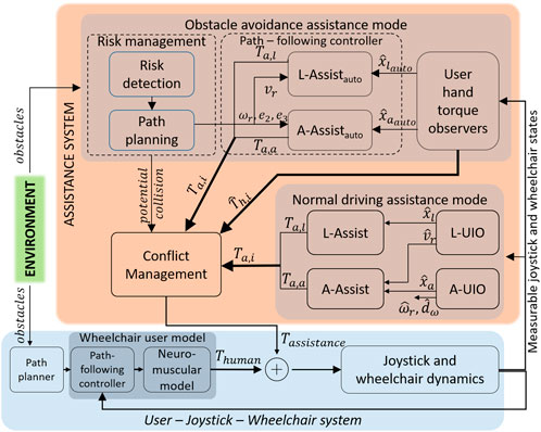
Figure 1 presents the overall system structure of the proposed model-based shared control approach for a power wheelchair driving assistance system using a force feedback joystick. Firstly, the human factors are considered in an augmented dynamic model of a user-joystick-wheelchair system. The wheelchair user model in the navigation task consists of a path planner, a path-following controller, and a neuromuscular model.
Secondly, the proposed AS consists of a conflict management function and two main operating modes: Normal Driving Assistance (NDA) and Obstacle Avoidance Assistance (OAA). The NDA operating mode is used when no risk of collision is detected. From the measurable states of the joystick and the wheelchair, the AS predicts the intentions of the user using Unknown Input Observers (UIO) and then assists the user in achieving their goal by applying haptic torques to the joystick thanks to the Longitudinal and Angular controllers, L-Assist and A-Assist, respectively. This haptic assistance reduces user effort when manipulating the joystick and, therefore, improves user comfort.
When the risk detection unit detects a risk of collision, the OAA operating mode is activated. The AS finds an optimal, collision-free path (thanks to the path planning unit) that is not too far from the actual path of the wheelchair. The path-following controller in OAA operating mode makes the wheelchair follow this optimal path like an autonomous robot by applying haptic torques to the joystick to modify the speed and direction of the wheelchair. This action also aims to intuitively inform the user about the risk of collision, suggest an alternative path, and guide the user to avoid the obstacle. If the user agrees with the suggestions of the AS, they work together until the risk is eliminated. On the other hand, if the user does not agree with the system suggestions (expressed through user’s hand torques applied to the joystick which are estimated by the UIO), the conflict management unit will switch AS to NDA operating mode to give the user the possibility to override the assistance system, resolve conflicts and thus improve the situation awareness for navigation safety and the acceptability of the system.
Extending our preliminary results from (Nguyen et al., 2020) in which the augmented dynamic model of the user-joystick-wheelchair system was developed, this paper presents the design steps of a completed AS (as shown in Figure 1) and includes extensive experimental results with the Human-Hardware-in-the-loop simulation to validate our proposed approach. The main contributions of this paper are summarized as follows.
1. A new model-based shared control approach for the design of an assistance system with a haptic force feedback control authority allocation between the power wheelchair user and the assistance system is proposed.
2. The proposed approach considers a user’s driving model interacting with his joystick and includes information about the user’s real-time intentions in the control design process, which offers an effective solution for the shared control issue, especially the personalization of the assistance system and conflicting situations avoidance.
3. The control design is based on a user-in-the-loop wheelchair system by combining robust control (operational part) with a high-level driving supervisor (tactical part) to improve the mutual user-automation understanding and to enhance the user situation awareness, especially during obstacle avoidance.
4. The consideration of the whole user-joystick-wheelchair system is particularly interesting from the point of view of the automatic control design. The closed-loop stability of the whole user-joystick-wheelchair system can be rigorously guaranteed using the Lyapunov stability argument.
5. The proposed new shared control and the user’s intention estimation approaches have been successfully validated with a human-hardware-in-the-loop simulator.
The remainder of this paper is organized as follows. The next section summarizes the development of the dynamic user-joystick-wheelchair model. Based on this whole model, the design of the shared control-based power wheelchair driving assistance system is presented in Section 3 and Section 4. Then, the human-hardware-in-the-loop validation results are presented in Section 5. Finally, some conclusions and future works are presented in the last section.
2 User-joystick-wheelchair dynamic model
This section summarizes the development of the dynamic user-joystick-wheelchair model presented in Nguyen et al. (2020)
2.1 User-joystick-wheelchair modeling
The power wheelchair is modelled as a unicycle robot, as shown in Figure 2, and its movements can be described by the following system under the no-slip assumption
where (x, y, φ) is the actual position of the wheelchair in the global coordinate system. v, ω are the actual longitudinal and angular velocities of the wheelchair, respectively. At each moment, the users determine the desired trajectory C which they want to track in the navigation task. To represent user intentions, we introduced a point P (xP, yP, φP) along the path C representing the desired wheelchair positions, together with the desired longitudinal and angular velocities (vr, ωr) as shown in Figure 2. The position errors of point P in the wheelchair body coordinate system are given by
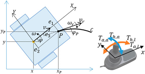
FIGURE 2. Kinematic model of the power wheelchair and joystick coordinate system with the applied torques.
As shown in Figure 2, e1 represents the look-ahead distance which is the distance between the wheelchair center of gravity CG and the desired position P in the longitudinal direction. e2 and e3 are the lateral and angular errors, respectively, which the user tries to minimize. Therefore (e1, e2, e3) and (vr, ωr) can be interpreted as the intention of the user in the next few moments, in terms of position and orientation.
To follow the desired path at the desired velocity vr, the user applies longitudinal and angular muscular torques, Th,l, Th,a respectively, to the joystick. The neuromuscular dynamics of these forces can be considered as a first-order transfer function (Sentouh et al., 2018) as follows
where i = l, a denotes the force of the user’s hand acting on the joystick for the longitudinal and lateral components. τm is the time constant representing the user’s processing time delay for transmitting information and the time reaction of the muscles. Th,i,ref are the desired torques of the user which can be modelled as the proportional-integral controller to minimize the velocity, lateral and angular errors as follows
where ev = vr − v is the velocity error. kp and ki are the parameters representing how the user reacts to the desired velocity. kre2 and kre3 are the parameters representing the effort of the user to change the wheelchair direction. These parameters allow to simulate the user driving behaviour during navigation task.
The hand-joystick dynamic model is represented by a second-order system (Marouf et al., 2017), as in
where θi (i = l, a) are the rotation angles of the joystick. Ji, Ki, Bi are the equivalent moment of inertia, stiffness, and viscosity of the hand-joystick system, respectively. Ta,a, Ta,l are the assistance haptic torques applied to the joystick in both directions. The dynamics of the wheelchair can be linked to the joystick angles as first-order systems as follows
where kyv, kxω are the coefficients related to the power amplifier characteristics of the joystick and the low-level controller. τyv, τxω are time constants of the dynamic response of the wheelchair.
2.2 State-space representation of the user-joystick-wheelchair model
The dynamics of the lateral position and linear speed errors can be described by
For the sake of simplicity, we assume that
where
In this model, the desired velocity vr of the user is considered as the unknown input and needs to be estimated, whereas the assistance torque Ta,l is the control input. Only the joystick position θl measurement is available in the real wheelchair system and therefore the output matrix is given as
where
In this model, the desired rotation speed of the user ωr is considered as the unknown input whereas the assistance torque Ta,a is the control input. For this system, only the joystick position θa and the real yaw rate ω can be directly measured and therefore, the output matrix is
3 Shared control for a power wheelchair driving assistance system
This section details the control design of the proposed shared control-based assistance system for power wheelchairs where the overall architecture is represented in Figure 1. Two unknown input observers for the longitudinal (L-UIO) and angular (A-UIO) system dynamics (respectively represented by (10); (11)), were designed to estimate simultaneously the state variables as well as the unknown inputs. The L-UIO estimates the state vector xl and the user desired velocity vr, considered as an unknown input, and the A-UIO estimates the state vector xa and the user desired yaw rate ωr, considered as an unknown input. Two controllers, L-Assist and A-Assist were designed using models (10) and (11) to provide the assistance torques Ta,l and Ta,a applied to the joystick.
L-Assistauto and A-Assistauto are two parts of a path-following controller that drive the wheelchair along the optimal path like an autonomous robot by providing the assistance torques Ta,l and Ta,a in OAA operating mode. They are designed based on the reduced versions of models (10) and (11) in which the user behavior model is not integrated. We use the same symbols Ta,i, i = l, a for the assistance torques in both operating modes. The conflict management function makes decisions about the assistance torques to be applied to the joystick, based on the risk of collision and conflict between the user and the AS. The conflict is detected by evaluating the estimated hand torques
In the following, the unknown input proportional-integral (PI) observer for the Tagaki-Sugeno (T-S) fuzzy models to estimate the user intention and the system states is Firstly presented. Then the LMI-based fuzzy optimal shared control approach to provide assistance torques on the joystick is given. Finally, the application of these approaches to the user-joystick-wheelchair dynamic system is presented.
3.1 T–S fuzzy observers design for User’s intention estimation
3.1.1 LMI-based unknown input observer design
Consider the following continuous-time T–S fuzzy system described by
where
To estimate simultaneously the states and unknown inputs of system 12, the Proportional-Integral observer for the T-S fuzzy model is proposed as follows (Ichalal et al., 2009)
where
Where
where
The design of this observer must not only ensure asymptotic stability but also satisfy the performance measures. In engineering practice, the most well-known criteria is the convergence rate of the observer (or decay rate of the estimation error). The observer design conditions are formulated in the following theorem.
Theorem 1. Tanaka et al. (1998) Given positive scalar α > 0. The decay rate of system 17 is at least α if there exists a matrix
where
3.1.2 User intention estimation
In this paper, user intention is defined by the position errors e2, e3 and desired speeds ωr, vr. e2, e3 and ωr are considered in angular dynamic model 11 which is non-linear with two time-varying parameters vr, e1. T-S model 12 has been adapted to represent model (11) with vr as the unique premise variable whereas e1 is considered as a constant. As vr cannot be measured directly, the membership functions were calculated based on the estimated value
Theorem 1 can now be applied to the T-S model of the user-joystick-wheelchair system 12 to design the Fuzzy unknown input observer (14) for the A-UIO block.
The L-UIO block estimates the desired velocity vr and the states of the longitudinal dynamic system 10. This is a linear time-invariant system, a special case of fuzzy model 12 with r = 1. Therefore, Theorem 1 can be applied to design the L-UIO block.
3.2 LMI-based fuzzy optimal shared control design
3.2.1 Control problem formulation
For the controller design, we consider the fuzzy state feedback controller which is designed based on the following parallel distributed compensation (PDC) law
where Li is the feedback gain matrix corresponding to ith subsystem and the Lyapunov function
We consider the following control problem.
Problem
Find the feedback gains matrices Li and matrix Pc such that the controller (21) stabilizes system (12) while minimizing the performance index:
along the solution of (12), where Q = QT > 0, R = RT > 0 are the weighting matrices with appropriate dimensions which should be appropriately chosen for shared control purposes.
3.2.2 Optimal controller design
The following theorem provides the LMI-based conditions for designing a state feedback controller to solve the above control problem.
Theorem 2. Given positive scalar γ > 0 and two matrices Q, R with appropriate dimensions. If there exists a matrix
with ζi = (γ, Ni, Pc),
solves the above control problem (Li et al., 2000).
Theorem 2 is then applied to the above T-S representation of angular dynamic model 11 to design state feedback controller (21) for the A-Assist block. The position errors and user effort should be minimized and therefore the performance matrix can be defined as:
The fuzzy optimal control presented in 3.2 is reduced to the well-known classical LQR control in the case of a linear system. Therefore, it can be applied to design the L-Assist block based on the linear longitudinal dynamic model (10).
Remark 1. The LMI conditions in Theorem 2 and Theorem 1 can be solved numerically with available solvers. In this work, the feedback gains Li, Ki i = {1, … , r}, were computed using SeDuMi solver version 1.3 and YALMIP toolbox for MATLAB Löfberg (2004).
4 Cooperative control strategy for shared control authority
4.1 Driving assistance operating modes
This part presents the design of both Normal Driving Assistance (NDA) and Obstacle Avoidance Assistance (OAA) operating modes.
The NDA operating mode consists of two unknown input observers (L-UIO and A-UIO) and two controllers (L-Assist and A-Assist) as shown in Figure 1. The main objective of this configuration is to estimate the user intention using the observers. The controllers then provide the haptic torques to assist the user in achieving their intentions.
The OAA operating mode is activated when a risk of collision is detected to inform the user about this risk and help them follow collision-free path proposed. This operating mode is deactivated when the risk is eliminated or a conflict between the user and AS is detected.
4.1.1 Conflict detection based on the user’s hand torque estimation
One important function of our proposed AS is the conflict management function. It is necessary to estimate the user hand torques to detect conflicts between the user and the AS. We exploit here the joystick dynamics 6) where the assistance torques Ta,i, i = l, a are applied to the joystick in both directions and are considered as the known inputs. System 6) is represented by state-space model with the state variable
Under the assumption that only the joystick angles θi are measurable, the PI-unknown input observer in 3.1 can be applied to estimate the user hand torques Th,i, i = l, a which are considered as the unknown inputs.
4.1.2 Path following controller
The main difference between the NDA and OAA operating modes is that latter does not consider the user model but works as an autonomous robot. In other words, the augmented user-joystick-wheelchair system is reduced to only a joystick-wheelchair system and user actions are considered as unknown inputs as in 4.1.1.
Therefore, to design the A-Assistauto block in OAA operating mode, we considered the reduced versions of the angular dynamic model (11) by setting the parameters kre2, kre3 to zero and removing the neuromuscular model 3). This leads to reduce the size of the system matrices. However, the nature of the system was conserved, which means that the reduced version of (11) is still a non-linear system with the varying parameters vr, e1 in the system matrix and the control input is still the angular assistance torque Ta,a. Furthermore, the position errors e2, e3 and reference yaw rate ωr are given by the path planning as shown in Figure 1, and do not, therefore, need to be estimated. Thus T-S representation 12 can be applied to this reduced system, where vr is still the premise variable within a range
to provide the assistance torques Ta,a in OAA operating mode.
A similar approach can be adapted to design the L-Assistauto block. By setting the parameters kp, ki to zeros and removing the neuromuscular dynamics, the longitudinal model (10) is reduced but is always a linear system with the assistance torque Ta,l as the control input. The reference velocity vr is given by the path planning block as shown in Figure 1. Therefore the LQR optimal controller in Section 3.2.2 can be applied to design the L-Assistauto providing the assistance torque Ta,l.
The human hand torque inputs are not considered in designing the controllers in OAA mode. Generally, it is reasonable to design a robust controller that rejects the effect of noise/disturbance to obtain the desired system performance. However, in this case, the main purpose of the above controllers was not to reject human actions but to communicate the intention of the AS to the user. If the AS rejects the user torque, it can make them feel confused if they suddenly feel a considerable reverse torque. Therefore, the above controller design did not consider the “external disturbance” of human hand torques.
4.2 Risk management
As mentioned in Section 1.2, the risk management block must detect the risk of collision and find the optimal alternative solution to avoid the obstacle. This section details each function of this block.
4.2.1 Potential collision detection
In this section, we assume that the obstacle positions and geometry are known beforehand. In a real confined environment, a few centimetres can affect collision or passage in the navigation tasks (Vander Poorten et al., 2012). Therefore, we also consider the wheelchair geometry in detecting potential collisions. A similar approach can be found in Vander Poorten et al. (2012) where the time-to-collision of a predicted circular path was used to formulate the guidance torques applied to the joystick. However, we argue that the users can change their desired trajectories very quickly, within a second. As a result, a collision detected in the next, 5s, for example, has no practical meaning. Therefore, we consider here a “prediction horizon” varying from 1sec to 1.5sec depending on the linear velocity of the wheelchair.
To predict the wheelchair position in the next few seconds, we have two options. The first one is to use the user intention estimation results as in Section 3.1.2. Although this method can estimate the desired position of the user in the next few moments based on the joystick dynamics, this position may not be the future position of the wheelchair. The second option is to use the joystick position, which is roughly proportional to the linear and angular velocities of the wheelchair, and kinematic model 1). Although this method is purely kinematic and neglects the joystick dynamics, it is widely accepted in prior studies (Vander Poorten et al., 2012; Devigne et al., 2016; Devigne et al., 2018; Kucukyilmaz and Demiris, 2018; Devigne et al., 2019). In this paper, this method is used to predict the future position of the wheelchair.
To perform the collision check, we defined all obstacles as connected segments. The wheelchair geometry has been simplified to a rectangular box and the collision check task was achieved by checking the intersections between the future positions of the wheelchair and the known edges of the obstacles.
4.2.2 Path planning
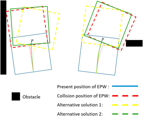
Once the potential collision is detected, the AS must find an alternative path. This path must be collision-free and not be too far from the actual future path of the wheelchair so that it is feasible and does not require too much user effort. Figure 3 illustrates our idea about the alternative solutions for obstacle avoidance. With the potential collision of the wheelchair (the red one), there are, for example, two possible substitute solutions. The yellow one is too far from the intention of the user, so the green one is selected as the optimal position because it satisfies both the above requirements. We only consider here obstacles near the wheelchair and hence, the proposed path is only “optimal” in this context.
By using the joystick positions which imply (v, ω) pair, potential collisions can be detected as described in Section 4.2.1. The optimal path finding problem can now be reduced to find an optimal (vopt, ωopt) pair that satisfies the two requirements above. We used here a “scan method” that numerically scans all the possible solutions, within mechanical limitations, of the pair (v, ω) and, minimizes the cost function
4.3 Conflict management
The objective of this block is to detect any disagreement between the user and the AS expressed through the interaction torques applied to the haptic joystick. This topic is often neglected in the literature even though it is one of the greatest issues in driving power wheelchairs (Viswanathan et al., 2017). In this research, conflict between the user and the AS is defined as the combination of the three following conditions.
1. The hand torques Th,i and the assistance torques Ta,i are in opposite directions, Th,i ⋅ Ta,i < 0, i = l, a;
2. In both longitudinal and lateral directions, the differences between the hand and assistance torques are greater than a predefined threshold torque Tcf, |Ta,i − Th,i| > Tcf, i = l, a;
3. Conditions 1 and 2 occur and are maintained for a period greater than a given period tthr.
The conflict conditions can be easily detected when the assistance and hand torques are known by the controllers and observers. However, the remaining problem is managing the risk and the conflict so that once the conflict is detected, the AS can be changed from OAA to NDA operating mode. Figure 4 shows the detailed operation of the conflict management block. The proposed algorithm uses four control variables: conflict, iscollis, risk, and solve_conflict to solve this problem. The detailed operational steps of this algorithm can be described as follows.
1. When there is no potential collision detected (iscollis = 0), the variables are set to 0 and the AS always stays in NDA operating mode.
2. When a potential collision is detected (iscollis = 1) and solve_conflict is still zero, the risk variable is set to 1. Then if isconflict is still zero OAA operating mode is activated. The user is now expected to sense the haptic torques that communicate a collision-free path. The user then make their decision by applying the appropriate torques to the joystick.
a. If there is no conflict between the user and the assistance torques (isconflict = 0), it means that the user agrees with the proposed path and the AS will stay in autonomous mode until no risk of collision is detected. The control loop is then repeated from step 1.
b. However, if a conflict is detected (isconflict = 1), it means that the user does not agree with the proposed path, and the assistance is switched to NDA operating mode to follow the user preferences after setting the variables isconflict to zero and solve_conflict to 1 to indicate that the conflict is solved for the next calculation loop.
3. After re-activating the NDA operating mode, as the conflict has been solved, even if a potential collision is still detected by the sensors (iscollis is still 1), the risk variable is set to 0 and the AS stays in this operating mode. Once the potential collision is eliminated iscollis = 0, the control loop is repeated from step 1.
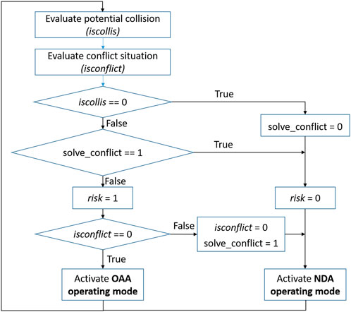
FIGURE 4. The detailed algorithm in the conflict management block contains four variables (isconflict, iscollis, solve_conflict and risk.).
5 Human-hardware-in-the-loop simulation
In this section, we present the experiments conducted to validate the proposed AS. Firstly, a virtual-reality simulator is introduced to integrate the user and the haptic joystick into the numerical simulation loop. The user-joystick wheelchair model was validated by identifying the parameters of the proposed models through measured inputs/outputs data. Then two functions of the NDA operating mode were validated: i) the estimation of user’s intention, and ii) the shared control-based assistance. Finally, the OAA mode was integrated into the validation tests to verify the efficiency of the proposed system.
5.1 Virtual reality simulator platform
To validate the proposed approach, we developed a virtual-reality simulator to integrate the wheelchair user and the force feedback joystick into the control loop. The general architecture of this simulator, as shown in Figure 5, includes four (04) main elements: a haptic force feedback joystick, an Arduino Mega 2,560 electronic board, the controllers and observers and the virtual-reality environment.
1. The force feedback joystick is a modified version of a commercial joystick. It is equipped with two electric direct current motors that work with a nominal voltage of 12 V. Each motor is attached to an axis to provide the user with assistance torques. To control the assistance torques, we used here a dual H-bridge power electronics board and the pulse-width modulation (PWM) method. Two potential dividers were used as the joystick position sensors to measure the rotation angles of the joystick. The maximum rotation angles of this joystick are 20o for each axis. The electronic board and two position sensors were connected to the Arduino Mega 2,560 board.
2. The Arduino board plays an intermediate role in this system. It reads the joystick positions using its Analog-Digital converters, converts the values to integer format, and then sends them to Simulink through the UDP connection thanks to its Ethernet shield. It receives the assistance torque values from Simulink through the UDP connection, converts them to the corresponding PWM values, and produces these torques by controlling two DC motors using its PWM modules. The source code for these Arduino functions was developed in Simulink thanks to the Arduino Support Package for Simulink. The sample time for the Arduino program was set to 0.01s.
3. The observer/controllers were implemented in Simulink Desktop Realtime to work in real-time conditions. The sample time was set to 0.01s. Models 1), 7), 8) were used to simulate the movement of the wheelchair in the virtual environment.
4. A virtual-reality scenario simulated the environment so that the user could experience different situations to verify the functions of the proposed AS. It was designed using the Simulink 3D toolbox, as in Figure 6.
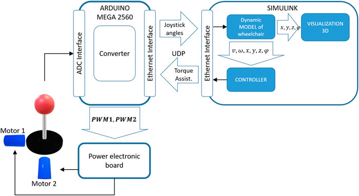
FIGURE 5. Virtual reality simulator for an electric wheelchair including a virtual scenario, a force feedback joystick, observers/controllers, and electronic boards.
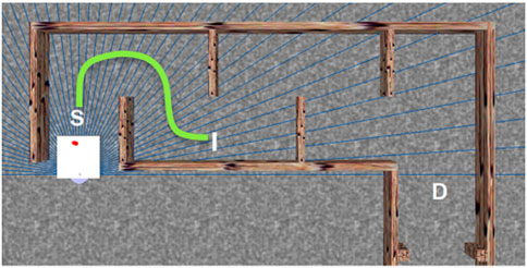
FIGURE 6. Simulation-experiment scenario. The green dot-line is the predefined reference path and the white square represents the wheelchair.
5.2 User-joystick wheelchair model validation
By using the virtual-reality simulator platform, the joystick and wheelchair users are involved in the control loop. The augmented model proposed in Section 2 consists of the user-path following model and dynamic model of the joystick which are now replaced by the real objects. Therefore, the parameters of these two models need to be identified.
To obtain data for this parameter identification step, four path-following experiments have been conducted on the virtual simulator platform where the predefined path is shown by the green line from point S to point I in Figure 6. In user-joystick-whelchair model 11, e1 = 0.1m was chosen as about half of the distance travelled in 1 s by a power wheelchair in a confined environment. This was based on the data published in Gillham et al. (2018) where 14 power wheelchair users ware required to carry out a navigation task in real-world tests. The data shows that the participants finished a course of 10.5m within about 60s. The obstacles in our virtual scenario were also adapted from the experimental setup in Gillham et al. (2018) where the participants commented that this setup was similar to the difficulties in their daily lives. We recorded the position of the wheelchair x, y, φ, the position errors e2, e3 from the virtual-reality environment, and the joystick angles θa, θl from the joystick position sensors. Then the model parameters were identified by using the Parameter Estimation toolbox in Simulink.
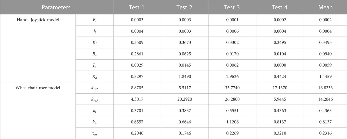
Figure 7 and Figure 8 present the estimation results of the proposed user-joystick model and the real responses of the participant. The responses of the model follow the trend of the real movements. There are some moments, for both velocity and yaw rate, where the simulated and real responses do not match. This may be due to the uncertainties in the way the user perceives their position errors and their reactions. In the proposed model, it is assumed that the reference points are located at a fixed distance in front of the wheelchair, so the user may choose a different point depending on the future curvature of the path. Table 1 summarizes the identified parameters from the above experiments.
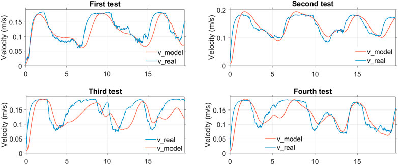
FIGURE 7. Simulation and experimental results of the four tests to identify the parameters of the longitudinal part of the user model.
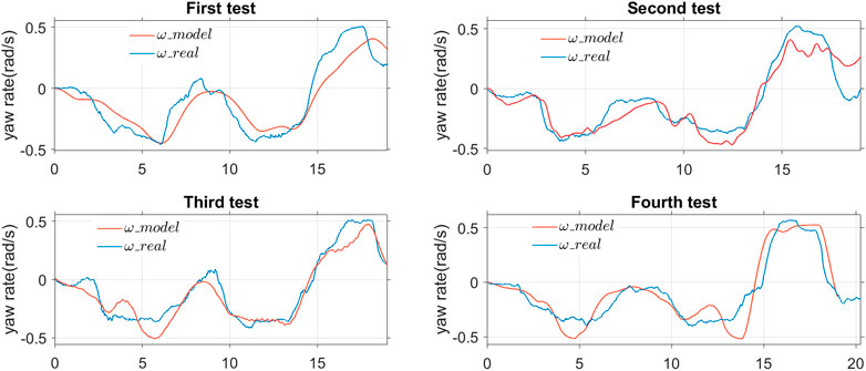
FIGURE 8. Simulation and experimental results of the four tests to identify the parameters of the rotational part of the user model.
5.3 Validation of the Normal Driving Assistance operating mode
The experiments in this section were conducted to validate two functions of the proposed AS in NDA operating mode: estimating the user intention and reducing user effort when manipulating the joystick. The wheelchair user was required to go from point S to point D two times in the virtual environment in Figure 6 without colliding with the virtual walls. The first time was without assistance torques and the second time was with assistance torques. With the assumption that e1 = 0.1m, user intention in this context is short-term intent. This means that we try to estimate what a human wants in the next about one second. In addition, differing from the experiments in Section 5.2 where the path was predefined, there ws no predefined path in these tests and the user was free to choose their desired movements to avoid collisions.
5.3.1 User intention estimation validation
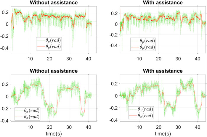
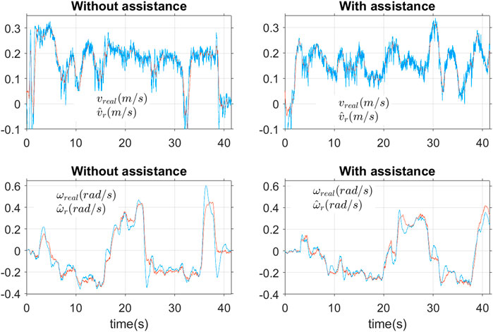
Figure 9 shows the filtered and raw results of the joystick angles during the two tests, with and without assistance. We can see that the recorded signal data are quite biased, especially the longitudinal angle of θy, and the estimated joystick angles converge to the real measured ones. Figure 10 presents the estimated results of the desired movements of the user including longitudinal velocity
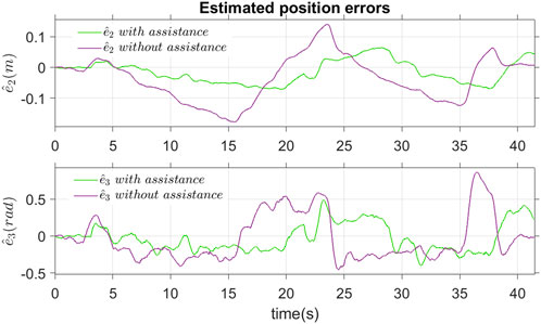
Figure 11 shows the estimated position errors with and without assistance torques. It can be seen that the lateral position error
5.3.2 Shared control-based assistance validation
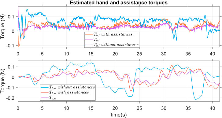
Figure 12 shows the hand and assistance torques with and without assistance. With assistance torques, in both the longitudinal and angular directions, the user only provided about half of the necessary torques compared to the case without assistance.
To adapt the assistance torques to user needs (e.g.they may require assistance depending on their health at a specific moment), the assistance should be adjustable. By varying the parameters kre2, kre3, kI, kP of the user - path - following controller, the proposed AS adjusts the assistance torques according to the desires of the user. To illustrate this result, we repeated the same experiment one more times and the parameters kre2, kre3, kI, kP were reduced to 50% of their values in Table 1. As can be seen in Figure 13 the hand torque was reduced considerably compared to the case in Figure 12. The assistance torques now account for the majority of the total torque necessary to manipulate the joystick.
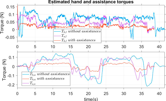
FIGURE 13. Estimation of user hand torques and assistance torques where the parameters could be adapted to user need.
5.4 Validation of obstacle avoidance assistance operating mode
In this section, we present the experiments conducted to validate the proposed AS in the OAA mode. The participant was required to repeat the same path as in the previous experiment without knowing that an additional obstacle had been inserted at the point O as in Figure 6. This obstacle was not visible to the participant but detected by the AS. The goal of this setup was to simulate a circumstance where the situation awareness of the user was different from that of the AS to validate the conflict management function of the proposed AS. The torque threshold Tcf was set to 0.2N and tthr was set to 1.5s and both were determined empirically. The pair (q, r) for the optimal path design was set to (25,1) to make sure the steering assistance had a higher priority than the speed assistance.
Figure 14 shows the path taken in the scenario designed and the position of the wheelchair when the risk of collision was detected. The risk management block detected the potential collisions and activated the OAA mode 4 times. In this experiment, all the potential collisions involved the front corners of the wheelchair. When there was no risk of a collision, the system provided about 50% of the required torque to manipulate the joystick, as shown in Figure 15. Otherwise, when a risk of collision appeared, the OAA mode was activated at 7.7s, 14s, 22.5s and 29s. The zoom of these moments is presented in Figure 16.
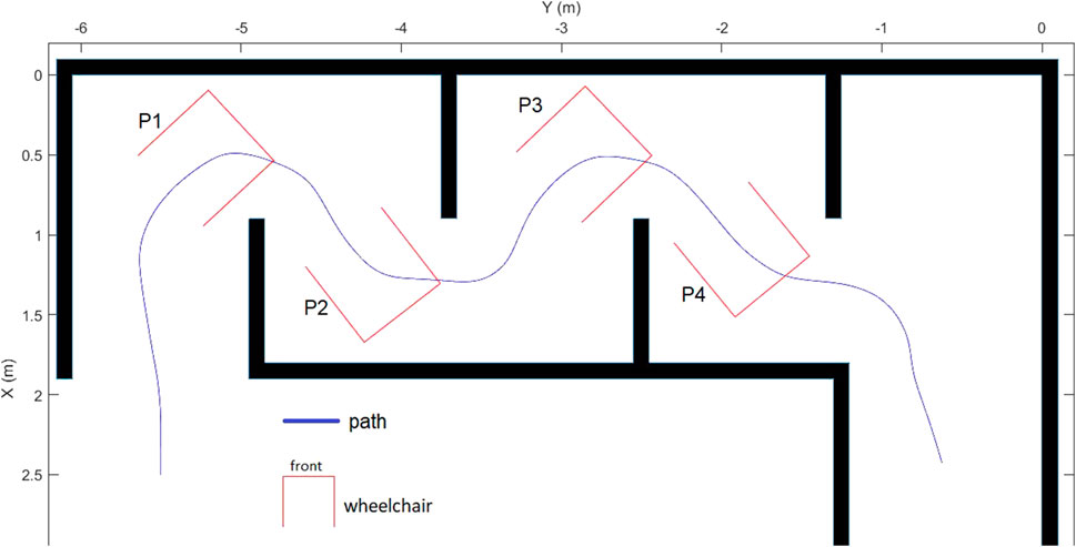
FIGURE 14. Path taken with the position of the wheelchair where the obstacle avoidance assistance is activated when the risk of collision is detected.
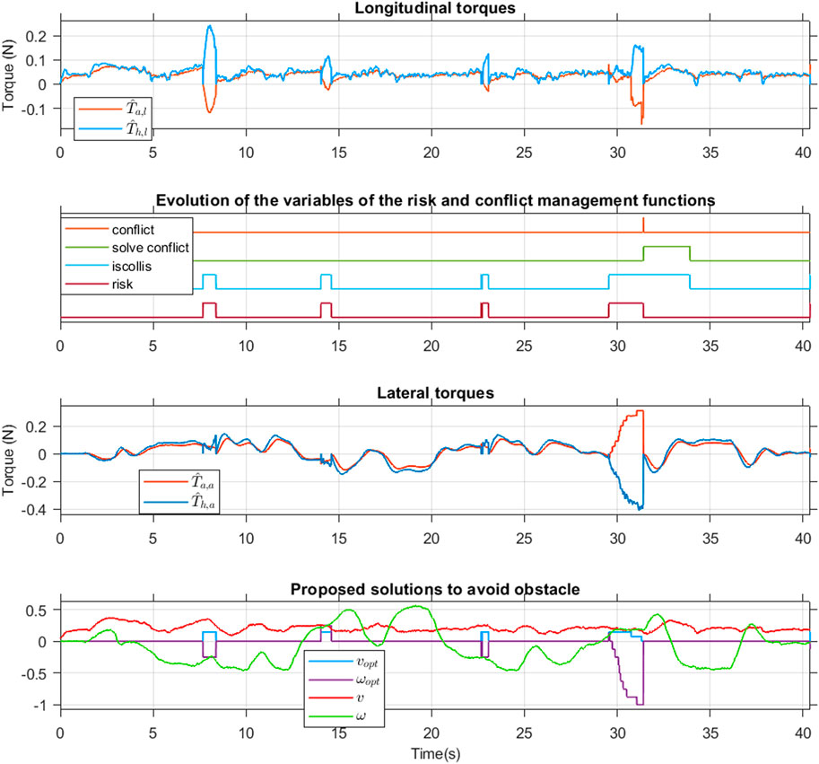
FIGURE 15. Evolution of the estimated hand torques, assistance torques and the variables of the risk-conflict management functions.
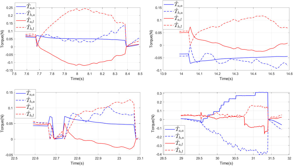
FIGURE 16. Evolution of the estimated hand torques and assistance torques when a risk of collision is detected.
In the longitudinal direction, the wheelchair user always seemed to disagree with the assistance torque. The 4 times a potential collision was detected, the longitudinal hand torque was always contrary to the assistance one and the user feel an resistance torque acting on his hand on the joystick. The response of the longitudinal velocity is consistent with the proposed optimal solution in Figure 15 where the real velocity decreased in accordance with the suggestion from the AS.
In the lateral direction, the user agreed more with the suggestion made by system. The hand torque had the same direction as the assistance for the first three potential collisions detected and the user feels a drop of assist torque at the moment where the AS swicth from OAA to NDA mode. Although the longitudinal hand and assistance torques were opposite these three times, no conflict was found between the user and the system. The reason is that with the assistance in the lateral direction, the system found that the risk of collision was eliminated and then it switched to NDA operating mode. Figure 15 illustrates these results when only two flags iscollis and risk are turned on, while the flags isconflict and solve conflict are still off.
The conflict between user intentions and the AS can be seen at point P4 in Figure 14 when the wheelchair approaches the additional obstacle described above. In this case, the proposed AS tried to guide the user along a different collision-free path by providing the haptic torque which gradually increases, as in Figure 15 and Figure 16. The user felt significant resistance at the joystick where AS had been trying to inform the optimal path. However, the user, unaware of the presence of the obstacle, tried to follow their initial intention by applying an opposing torque to the joystick. Once the three conditions in Section 4.3 were verified, the conflict between the user and the system was confirmed and the flag isconflict switched on, as in Figure 15. In this case, the system then had to switch to NDA operating mode, the user would feel a sudden drop in haptic torque at the moment of switching when AS waited for the user’s actions. . Therefore the flag solve conflict was switched on and the isconflict and risk flags turned off. The flag solve conflict is maintained until the iscollis flag is turned off to avoid continuously switching between NDA and OAA operating modes.
It should be noted that when the assistance mode is switched between NDA and OAA modes, the initial conditions of the observers are reset to zero, and therefore, the estimated torques are also reset to zero, as shown in Figure 15.
5.5 Toward a real-life application
The experimental results confirmed the operation of the assistance system in both NDA and OAA operating modes in a simulated environment. In a real scenario, where the environment is generally more complicated and external disturbances affect the user and the wheelchair dynamics, this system is also expected to work well with an appropriate configuration. Firstly, the parameters kre2, kre3, kI, kP of the user driving model must be calibrated according to the user’s profile. The parameters can even be changed when the wheelchair is moved with a simple hardware (e.g., a potentiometer). In OAA mode, the effectiveness of the conflict management algorithm was proven by the results of the experiments. The performance of this algorithm is based on the T-S fuzzy unknown input PI observer where the convergence has been demonstrated. This algorithm is designed to cover all cases of relationships between the hand and the assistance torques. However, the authors point out two main reasons that can lead to abnormal behaviour of the AS. The first reason is related to the presence of faults in the sensors which lead to a bad torques estimation or perception of the situation. This cause can be corrected by improving the reliability of the sensors. The second reason is that the optimal path proposed by the AS is only valid for nearby obstacles. This means that this path may not be optimal if the user’s anticipation is much higher and therefore conflicts may occur, which decreases user comfort. This problem should be solved by combining this system with a more efficient trajectory planner with long-range performance sensor.
6 Conclusion
In this paper, a new model-based shared control approach for power wheelchair assistance through a force feedback joystick has been proposed. Based on the user’s intention estimation, this proposed assistance system is able to reduce the user effort when manipulating the joystick, guide them to avoid a potential collision and preserve their role as the final decision maker. By introducing an augmented dynamical model of the user-wheelchair system, the unknown input observers were designed to estimate user intention. The optimal T-S fuzzy controller has been designed to handle the time-varying user’s intention and to provide haptic torque feedback to the user. To manage the control authority between the user and the automation, a cooperative control strategy has been proposed, and two main operating modes were defined: 1) the Normal Driving Assistance (NDA) mode and ii) the Obstacle Avoidance Assistance (OAA) mode. For the OAA mode, a path following controller was designed to provide an appropriate haptic guidance. We have also developed conflict management functions based on the user’s haptic torque applied to the joystick, estimated using the designed UIO. Experiments were conducted using a human-hardware-in-the-loop simulator with a haptic joystick developed in our laboratory to validate the proposed approach. The experimental results have demonstrated the effectiveness of the proposed approach and confirmed all the intended functions. The conflict management function allowed users to communicate their intentions and overrule the guidance of the system effectively to maintain their active participation in driving the wheelchair.
Future works will be focused on the evaluation of the proposed assistance system by conducting experiments on the LAMIH PSCHITT-PMR full scaled wheelchair dynamic simulator for real-world experiments with the participation of able-bodied and disabled peoples.
Data availability statement
Publicly available datasets were analyzed in this study. This data can be found here: https://pubmed.ncbi.nlm.nih.gov/29552641/.
Author contributions
All the authors contributed to the presented idea, the design and the implementation, the analysis of the results, and the writing of the manuscript.
Funding
This work was supported by the RITMEA research program funded by the European Regional Development Fund, the State, and the Hauts-de-France Region. This work was also sponsored by the Regional Delegation for Research and Technology, the Ministry of Higher Education and Research and the French National Center for Scientific Research.
Conflict of interest
The authors declare that the research was conducted in the absence of any commercial or financial relationships that could be construed as a potential conflict of interest.
Publisher’s note
All claims expressed in this article are solely those of the authors and do not necessarily represent those of their affiliated organizations, or those of the publisher, the editors and the reviewers. Any product that may be evaluated in this article, or claim that may be made by its manufacturer, is not guaranteed or endorsed by the publisher.
References
Carlson, T., Del, R., and Millan, J. (2013). Brain-controlled wheelchairs: A robotic architecture. IEEE Robotics Automation Mag. 20, 65–73. doi:10.1109/MRA.2012.2229936
Carrington, P., Hurst, A., and Kane, S. K. (2014). “Wearables and chairables: Inclusive design of mobile input and output techniques for power wheelchair users,” in Proceedings of the 16th international ACM SIGACCESS conference on computers and accessibility (New York, NY, USA: Association for Computing Machinery), 201–208. doi:10.1145/2556288.2557237
Demeester, E., Hüntemann, A., Philips, J., Van Brussel, H., Vanacker, G., Vanhooydonck, D., et al. (2010). Adaptable navigational assistance for intelligent wheelchairs by means of an implicit personalized user model. Robotics Aut. Syst. 58, 963–977. doi:10.1016/j.robot.2010.04.002
Devigne, L., Narayanan, V. K., Pasteau, F., and Babel, M. (2016). “Low complex sensor-based shared control for power wheelchair navigation,” in Proceedings of the IEEE International Conference on Intelligent Robots and Systems, Daejeon, Korea, October 9-14, 2016, 5434–5439. doi:10.1109/IROS.2016.7759799
Devigne, L., Pasteau, F., Babel, M., Narayanan, V., Gallien, P., Devigne, L., et al. (2018). “Design of a haptic guidance solution for assisted power wheelchair navigation,” in Proceedings of the 2018 IEEE International Conference on Systems, Man, and Cybernetics (SMC), Miyazaki, Japan, October 7- 10, 2018, 3231–3236. doi:10.1109/SMC.2018.00547
Devigne, L., Pasteau, F., Carlson, T., and Babel, M. (2019). “A shared control solution for safe assisted power wheelchair navigation in an environment consisting of negative obstacles: A proof of concept,” in Proceedings of the IEEE International Conference on Systems, Man and Cybernetics, Bari, Italy, 06-09 October 2019, 1043–1048. doi:10.1109/SMC.2019.8914211
Gillham, M., Pepper, M., Kelly, S., and Howells, G. (2018). Feature determination from powered wheelchair user joystick input characteristics for adapting driving assistance. Wellcome Open Res. 2 (93), 93–40. doi:10.12688/wellcomeopenres.12280.3
Ichalal, D., Marx, B., Ragot, J., and Maquin, D. (2009). “Simultaneous state and unknown inputs estimation with PI and PMI observers for Takagi Sugeno model with unmeasurable premise variables,” in 17th Mediterranean Conference on Control and Automation, Thessaloniki, Greece, 24-26 June 2009, 353–358. doi:10.1109/med.2009.5164566
Iturrate, I., Antelis, J. M., Kübler, A., and Minguez, J. (2009). A noninvasive brain-actuated wheelchair based on a P300 neurophysiological protocol and automated navigation. IEEE Trans. Robotics 25, 614–627. doi:10.1109/TRO.2009.2020347
Jain, S., and Argall, B. (2014). “Automated perception of safe docking locations with alignment information for assistive wheelchairs,” in Proceedings of the IEEE International Conference on Intelligent Robots and Systems, Chicago, IL, USA, 14-18 September 2014, 4997–5002. doi:10.1109/IROS.2014.6943272
Kucukyilmaz, A., and Demiris, Y. (2018). Learning shared control by demonstration for personalized wheelchair assistance. IEEE Trans. Haptics 11, 431–442. doi:10.1109/TOH.2018.2804911
Leishman, F., Horn, O., and Bourhis, G. (2010). Smart wheelchair control through a deictic approach. Robotics Aut. Syst. 58, 1149–1158. doi:10.1016/j.robot.2010.06.007
Li, J., Wang, H. O., Bushnell, L., and Hong, Y. (2000). A fuzzy logic approach to optimal control of nonlinear systems. 10.1.1.37.3750.
Löfberg, J. (2004). “Yalmip: A toolbox for modeling and optimization in MATLAB,” in Proceedings of the 2004 IEEE International Conference on Robotics and Automation, Taipei, Taiwan, 02-04 September 2004, 284–289. doi:10.1109/CACSD.2004.1393890
Marouf, A., Pudlo, P., Sentouh, C., and Djemaï, M. (2017). Investigation of the driver’s arm viscoelastic properties during steering vehicle maneuver. IEEE Trans. Syst. Man, Cybern. Syst. 47, 1030–1036. doi:10.1109/TSMC.2016.2523915
Morales, Y., Kallakuri, N., Shinozawa, K., Miyashita, T., and Hagita, N. (2013). “Human-comfortable navigation for an autonomous robotic wheelchair,” in Proceedings of the IEEE International Conference on Intelligent Robots and Systems, Tokyo, Japan, 03-07 November 2013, 2737–2743. doi:10.1109/IROS.2013.6696743
Morere, Y., Hadj Abdelkader, M. A., Cosnuau, K., Guilmois, G., and Bourhis, G. (2015). Haptic control for powered wheelchair driving assistance. IRBM 36, 293–304. doi:10.1016/j.irbm.2015.09.003
Nguyen, V. T., Sentouh, C., Pudlo, P., and Popieul, J.-C. (2018). “Path following controller for electric power wheelchair using model predictive control and transverse feedback linearization,” in Proceedings of the 2018 IEEE International Conference on Systems, Man, and Cybernetics (SMC), Miyazaki, Japan, 07-10 October 2018, 4319–4325. doi:10.1109/smc.2018.00730
Nguyen, V. T., Sentouh, C., Pudlo, P., and Popieul, J. C. (2020). “Joystick haptic force feedback for powered wheelchair - a model-based shared control approach,” in 2020 IEEE International Conference on Systems, Man, and Cybernetics (SMC), Toronto, ON, Canada, 11-14 October 2020, 4453–4459. doi:10.1109/SMC42975.2020.9283235
Nisbet, P. D. (2002). “Who’s intelligent? Wheelchair, driver or both?,” in Proceedings of the IEEE International Conference on Control Applications, Glasgow, UK, 18-20 September 2002, 760–765. doi:10.1109/CCA.2002.1038696
Park, J. J., and Kuipers, B. (2011). “A smooth control law for graceful motion of differential wheeled mobile robots in 2D environment,” in Proceedings - IEEE International Conference on Robotics and Automation, Shanghai, China, 09-13 May 2011, 4896–4902. doi:10.1109/ICRA.2011.5980167
Sentouh, C., Nguyen, A. T., Floris, J., and Popieul, J. C. (2018). “Multiple controller switching concept for human-machine shared control of lane keeping assist systems,” in Proceedings of the 2018 IEEE International Conference on Systems, Man, and Cybernetics (SMC), Miyazaki, Japan, 07-10 October 2018, 2730–2735. doi:10.1109/SMC.2018.00466
Simpson, R. C. (2009). How many people would benefit from a smart wheelchair? J. Rehabilitation Res. Dev. 45, 53–72. doi:10.1682/jrrd.2007.01.0015
Tanaka, K., Ikeda, T., and Wang, H. O. (1998). Fuzzy regulators and fuzzy observers: Relaxed stability conditions and LMI-based designs. IEEE Trans. Fuzzy Syst. 6, 250–265. doi:10.1109/91.669023
Vander Poorten, E. B., Demeester, E., Reekmans, E., Philips, J., Hüntemann, A., and De Schutter, J. (2012). “Powered wheelchair navigation assistance through kinematically correct environmental haptic feedback,” in Proceedings of the IEEE International Conference on Robotics and Automation, Saint Paul, MN, USA, 14-18 May 2012, 3706–3712. doi:10.1109/ICRA.2012.6225349
Viswanathan, P., Zambalde, E. P., Foley, G., Graham, J. L., Wang, R. H., Adhikari, B., et al. (2017). Intelligent wheelchair control strategies for older adults with cognitive impairment: User attitudes, needs, and preferences. Aut. Robots 41, 539–554. doi:10.1007/s10514-016-9568-y
Keywords: powered wheelchair, assistance system, haptic joystick, optimal fuzzy control, conflict management
Citation: Nguyen VT, Sentouh C, Pudlo P and Popieul J-C (2023) Model-based shared control approach for a power wheelchair driving assistance system using a force feedback joystick. Front. Control. Eng. 4:1058802. doi: 10.3389/fcteg.2023.1058802
Received: 30 September 2022; Accepted: 23 January 2023;
Published: 13 February 2023.
Edited by:
Francisco J. Vargas, Federico Santa María Technical University, ChileReviewed by:
Douglas Plaza, ESPOL Polytechnic University, EcuadorEnrique D Ferreira-Vazquez, Universidad Católica del Uruguay, Uruguay
Copyright © 2023 Nguyen, Sentouh, Pudlo and Popieul. This is an open-access article distributed under the terms of the Creative Commons Attribution License (CC BY). The use, distribution or reproduction in other forums is permitted, provided the original author(s) and the copyright owner(s) are credited and that the original publication in this journal is cited, in accordance with accepted academic practice. No use, distribution or reproduction is permitted which does not comply with these terms.
*Correspondence: Viet Thuan Nguyen, bmd1eWVudmlldHRodWFuMTk4N0BnbWFpbC5jb20=
 Viet Thuan Nguyen
 Chouki Sentouh
 Philippe Pudlo1