 Hanjie Wang
 Kenneth J. Hunt
- RehaLab - The Laboratory for Rehabilitation Engineering, Institute for Human Centred Engineering HuCE, Division of Mechatronics and Systems Engineering, Department of Engineering and Information Technology, Bern University of Applied Sciences, Biel, Switzerland
Introduction: With conventional heart rate (HR) control systems, the exercising person is bound to walk or run at a pace determined by the feedback. This may be challenging for people with impairments that make it difficult for them to achieve a smooth, continuous pace. The aim of this work was to assess the technical feasibility of a novel self-paced heart rate control strategy and to compare its accuracy with conventional heart rate control.
Methods: We propose a self-paced heart rate control system that embeds an automatic positioning controller within the heart rate control loop. The treadmill speed command is decoupled from the heart rate compensator, whereas speed is determined by the exerciser’s own volition: target speed is displayed visually to the person and, when they try to follow this target, the position controller sets the treadmill speed while keeping the person at a safe reference position on the track. A further novel contribution of this work is a new input-sensitivity-shaping, frequency-domain design strategy for feedback control of position.
Results: Experimental evaluation with four participants showed that self-paced heart rate control is technically feasible: all participants were able to accurately follow the target running speed calculated by the HR compensator and presented to them visually; for all four participants, self-paced HR tracking accuracy was not substantially different from conventional HR control performance; on average, the self-paced heart rate controller gave slightly better performance than conventional HR control, with RMS tracking error of 2.98 beats per minute (bpm) vs 3.11 bpm and higher average control signal power.
Conclusion: The proposed self-paced heart rate control strategy with embedded automatic position control is deemed feasible. This approach may be helpful for people with gait impairments or other limitations that make it difficult for them to follow an imposed treadmill speed.
1 Introduction
Feedback control of heart rate (HR) can be used to optimise exercise training and testing routines (Hunt and Fankhauser, 2016; Wang and Hunt, 2021a). When applied using a treadmill for walking or running, the exercising person is bound to walk or run at the speed determined by the feedback control algorithm: the latter continuously adjusts treadmill speed to maintain a target heart rate. This constraint can be problematic if the person is unable or unwilling to maintain the commanded treadmill speed, in which case the exercise has to be interrupted or stopped to ensure safety; this can be done by the person stepping to the side of the treadmill track or pressing the emergency stop, or by a signal to an external person who has the ability to stop the treadmill. But a rapid stopping of the treadmill in itself carries risk because high acceleration may challenge the person’s balance thus leading to a fall. These factors become especially relevant in the context of rehabilitation of patients with gait impairments, where walking or running at a smooth, continuous pace might be difficult and balance control compromised.
To solve this problem, the present work developed a self-paced heart rate control methodology wherein a conventional heart rate controller is combined with an automatic position controller, resulting in a so-called “self-paced heart rate control” approach. Here, the HR controller works as normal to continuously adjust the commanded treadmill speed. Instead of sending the speed command directly to the treadmill, however, the target speed is merely displayed to the walker/runner together with the actual treadmill speed, and they can then decide on their own volition whether they wish to, and are able to, follow this target. The actual treadmill speed is determined by a second feedback controller for position that is designed to maintain the exerciser at, or close to, a safe reference location on the treadmill.
In this setup, therefore, the exerciser’s walking/running speed is only indirectly coupled to the target speed from the HR compensator: the treadmill is commanded by the position controller, which in turn is responding to the person’s freely-selected walking/running speed, meaning that the treadmill is effectively under the exerciser’s control. Of course, the intention is that the exerciser will be able to follow the target speed from the HR compensator by means of the visual feedback of the target and actual treadmill speeds, but this target speed is not strictly imposed on the person as in conventional HR control. This means that the person’s safety, as far as their location on the treadmill is concerned, is ensured irrespective of the target speed computed by the HR controller.
Should the user be unable or unwilling to follow the target treadmill speed, then the heart rate feedback loop is not closed, in which case the only controller is the position controller which works to keep the user at the reference position, irrespective of what walking/running speed the person chooses. However, our working assumption throughout this paper, and in the experimental evaluation, is that the user is doing their best to follow the target, so the heart rate feedback loop is closed.
While the concept of automated positioning on a treadmill is not new—it is a technique that has commonly been referred to as “self-paced treadmill,” or SPT—the embedding of a position controller within the HR control system to form the self-paced heart rate controller is a new concept that is presented and evaluated here.
Several self-paced treadmill (SPT) strategies have been proposed in the past, with the aim of automatically keeping the exerciser at a safe position. One possibility is a passive approach using a curved treadmill that requires neither sensors to determine position nor actuators to drive the treadmill (Kim et al., 2017). A more common solution is to measure position and to employ feedback control using a motor-driven treadmill. Some studies adopted a camera motion capture system using body markers for position measurement and a weighted proportional-derivative (PD) compensator for position control (Sloot et al., 2014; Plotnik et al., 2015; Wiens et al., 2019). Other work measured distance with an ultrasound sensor and implemented an acceleration/deceleration control strategy to position the runner within 11 zones on the treadmill track (Scheadler and Devor, 2015). We previously used a wire-draw encoder for distance measurement and a feedback controller design based on closed-loop time-response tuning (Hunt et al., 2018).
Recent studies have shown that treadmill exercise using self-paced (with position feedback) or fixed-speed strategies have similar kinetic and kinematic characteristics (Sloot et al., 2014; Plotnik et al., 2015; Wiens et al., 2019), muscle activity (Ibala et al., 2019) and energy cost (Theunissen et al., 2022). Moreover, analysis of spatiotemporal data from walking tests with SPT shows more natural fluctuations and a reduction of speed-related constraints (Wiens et al., 2019). It is natural to assume that these properties of SPT exercise carry over to the method of self-paced HR control described in the following.
While there is currently no data regarding the influence of speed visual-feedback on HR control performance, recent studies in gait rehabilitation using treadmill exercise have shown that introducing visual feedback has a positive influence on training outcomes in different pathologies, e.g., cerebral palsy, stroke or Parkinson’s disease, signified by reduction in gait asymmetry, increased mobility (Liu et al., 2020) and improved balance (Almeida and Bhatt, 2012; Levin et al., 2017). A potential reason for these benefits is that, with visual-feedback, participants can better adapt their motion, such as by optimising their gait pattern to compensate the impairments associated with their condition. Positive adaptations have been verified by a reduction in oxygen cost (Levin et al., 2017), improvement of assessment of life habits after training (Tobar et al., 2018) and an increase in step length (Almeida and Bhatt, 2012; Liu et al., 2020). These adaptations and benefits may carry over as potential side benefits of self-paced HR control, due to the incorporation of a visual feedback task: this is a stimulating activity which challenges (in a positive sense) the active processing networks of the central nervous system.
In the present work, we employ a tethered approach in the self-paced HR controller by using a wire-draw encoder for position measurement (as in (Hunt et al., 2018)), although any other method of determining position is in principle compatible with the position controller (e.g., a non-contact ultrasound sensor). A further, novel contribution presented in the sequel is that a new closed-loop input-sensitivity-shaping, frequency-domain design strategy is proposed for feedback control of position. This approach is taken in order to avoid unwanted excitation of the control signal (i.e., the treadmill speed command) by the periodic fluctuations in the distance measurement signal resulting naturally from the cyclical gait pattern: these fluctuations can be regarded as a disturbance signal entering the feedback loop, and they have to be expressly considered as part of the feedback design.
With reference to a standard feedback control system with compensator C and nominal plant Po, classical loop shaping is based upon shaping of the open-loop gain function Lo = CPo, which then leads indirectly to the corresponding frequency responses of the closed-loop sensitivity functions (Åström and Murray, 2008). Alternatively, the closed-loop sensitivity functions can be shaped directly (Diaz et al., 2019) but closed-loop shaping has principally considered the sensitivity and complementary sensitivity functions, usually denoted So and To, respectively. In our work, we focus instead on direct shaping of the closed-loop input sensitivity function, denoted Uo (Kwakernaak, 1993), because this function determines the behaviour of the control signal. Here, the control signal is the physical treadmill speed which is directly experienced by the user, and which must therefore be made to behave well.
Since, in this combined-controller setup, the proper functioning of the HR controller is now dependent on the ability of the walker/runner to maintain the target speed demanded by the HR controller, it remains to verify whether there is any loss of HR control accuracy compared to the case of conventional HR control. We have previously conducted extensive studies of conventional HR control during treadmill running, (Hunt and Fankhauser, 2016; Wang and Hunt, 2021a), which demonstrated average root-mean-square HR tracking errors (RMSE) on the range of about 2–3 beats per minute (bpm): this range serves as a baseline in the present work for assessment of the relative performance of the new self-paced HR control strategy.
The novel aspects and merits of the present work can be summarised as follows:
• We present a novel strategy for self-paced heart rate control, which has not previously been considered: this approach may be helpful for people with gait impairments or other limitations that make it difficult for them to maintain an imposed treadmill speed.
• We describe a new frequency-domain method for position controller tuning based on closed-loop input-sensitivity shaping. Previous work on closed-loop shaping has considered only the sensitivity and complementary sensitivity functions, whereas the behaviour of the control signal, which is determined by the closed-loop input sensitivity function, is paramount in this application.
• We also aimed to conduct experiments to empirically assess the technical feasibility of the proposed self-paced HR controller and to compare its accuracy with conventional heart rate control.
2 Methods
2.1 Controller design
The treadmill setup, dynamics and key variables are shown in Figure 1: the speed of treadmill track is denoted vt while the commanded speed (sent from the control computer) is
where x0 is the initial position.
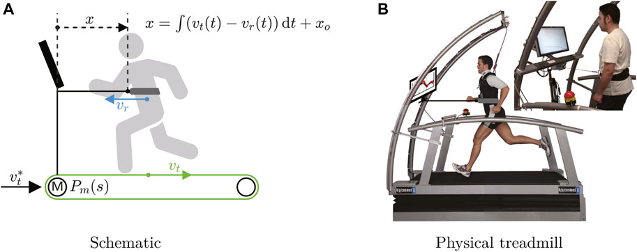
FIGURE 1. Treadmill setup, dynamics and key variables. (A)
2.1.1 Conventional heart rate controller
For the conventional (i.e., non-self-paced) heart rate control system (Figure 2A, detailed in (Wang and Hunt, 2021a)), the compensator Ch(s) computes the treadmill speed command
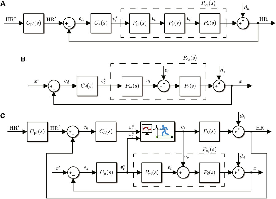
FIGURE 2. Block diagrams of the conventional HR and distance controllers, and the combined structure for self-paced HR control. (A) Conventional heart rate control system. HR* is the target heart rate profile, HR is the actual heart rate, and HR’ is the output of reference prefilter Cpf(s). The nominal plant is
The transfer function
Following the results of the identification study in (Wang and Hunt, 2021b), we proceed on the assumption of a nominal first-order plant
with gain k = 28.57 bpm/(m/s) and time constant τ = 70.56 s (these specific values were determined in (Wang and Hunt, 2021b) as averages from 11 individually-identified participants).
In summary, in the conventional heart rate control structure, the treadmill track speed is set automatically by the heart rate compensator and the exerciser is required to walk or run at approximately the same speed as the treadmill track such that they maintain their position at a safe location on the track.
2.1.2 Conventional position controller: Self-paced treadmill
In the conventional (i.e., without the incorporation of heart rate) position/distance control system (Figure 2B, detailed in (Hunt et al., 2018)), the compensator Cd(s) continuously updates the commanded treadmill speed
The transfer function
In contrast to the conventional heart rate control system, with the conventional position controller the exerciser can arbitrarily choose their own speed, giving rise to the concept of “self-paced” treadmill (SPT). Distance measurement feedback then allows the compensator to automatically set the track speed to eliminate any deviation from the position setpoint and, in so doing, to keep the track speed vt close to the self-selected runner’s speed vr.
2.1.3 Combined controller: Self-paced heart rate control
The proposed self-paced heart rate control system (Figure 2C) has two key characteristics: (i) the position/distance controller is embedded within the heart rate control loop, and (ii) the heart rate compensator output is decoupled from direct connection to the treadmill; in the conventional HR control system (Figure 2A), the output of the heart rate compensator Ch is the commanded treadmill speed
Visual feedback is provided to the exerciser on a screen that displays two signals: the runner’s target speed
As can be seen in the block diagram of the self-paced HR controller (Figure 2C), the runner’s self-selected speed vr serves as an input (actually, a disturbance input) to the distance control loop, which then drives the commanded response speed of the treadmill
2.1.4 Feedback design
Synthesis of the heart rate and distance compensators Ch and Cd proceeds from a generic nominal plant model Po(s), viz. the strictly proper rational function
where A and B are polynomials of degree na and nb, and A is monic. The specific instances of Po used in the sequel for calculation of Ch and Cd are given in Eqs 2, 3, respectively.
The compensators Ch and Cd are both strictly proper rational functions that are constrained to include integral action and which have the form
where G and H are polynomials of degree ng and nh, with H monic. The strictly proper requirement, expressed algebraically as ng < nh, is to ensure the compensator gain rolls off to zero, i.e., limω→∞|C(jω)| = 0, to make the controller insensitive to high-frequency disturbances. The integral action is to guarantee zero steady-state error (for the heart rate compensator, this means compensation of the very slow Phase III dynamics of HR response).
Derivation of both Ch and Cd is based on a frequency-domain, loop-shaping approach focused on the input sensitivity function. For completeness, the three principal sensitivity functions, i.e., the sensitivity function So, the complementary sensitivity function To, and the input sensitivity function Uo, are defined here:
For further development, the latter expression for the input sensitivity function Uo can be expressed in terms of polynomials by substitution for Po and C using Eqs 4, 5, respectively, as
2.1.4.1 Heart rate controller design
The main design challenge for HR control is to ensure that the control signal
To address these requirements, the heart rate compensator Ch(s) is designed by algebraic manipulation to give a specific shape to the input sensitivity function for the HR control loop:
where k is the plant’s steady-state gain (see Eq. 2). The rationale for this choice of
Full details of the compensator derivation are given elsewhere, (Hunt and Fankhauser, 2016), while the solution is summarised here: for the nominal plant Eq. 2, the compensator that has the general form of Eq. 5 and that achieves the desired form in Eq. 10 for the input sensitivity function is
The compensator is parameterised by the design parameter p (bandwidth specification for
The prefilter Cpf is designed to shape the overall closed-loop transfer function from HR* to HR to be a second-order transfer function, denoted Tcl, with critical damping and rise time of 150 s. Since
2.1.4.2 Distance controller design
It is important to design the distance control system to make sure that the disturbance term dd does not inappropriately excite the control signal, i.e., the treadmill speed command
To address these requirements, the distance compensator Cd(s) is designed to shape the input sensitivity function
In the following, we develop a novel optimisation-based design approach for synthesis of the distance compensator. Cd is chosen to have the general form of Eq. 5 so that it is strictly proper and includes integral action. Assuming a nominal plant as in Eq. 3, where
With this definition of G and H, and using plant polynomials B(s) = 1 and A(s) = s (Eq. 3), the input sensitivity function is obtained from Eq. 9 as
where Φ(s) is the closed-loop characteristic polynomial, Φ(s) = s3 + h0s2 + g1s + g0. Assuming all three closed-loop poles are real, Φ can be expressed as
where, for stability, a, b and c are positive. Apparently, h0 = a + b + c, g1 = ab + bc + ac and g0 = abc.
Controller synthesis is now formulated as an optimisation problem that aims to find the a, b and c that shape
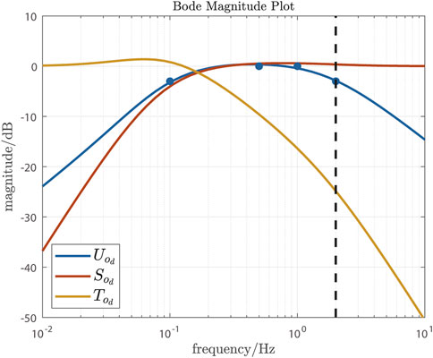
FIGURE 3. Closed-loop sensitivity functions for the distance control loop: input-sensitivity function
The optimal a, b and c were obtained by least-squares using the matlab non-linear curve fitting function lsqcurvefit (Matlab, The MathWorks, Inc., USA), giving a = 0.5439, b = 0.5437 and c = 10.6170. Since h0 = a + b + c, g1 = ab + bc + ac and g0 = abc, the distance compensator Cd is
With this compensator and the nominal plant
2.2 Experimental methods
We used an experimental, small-group study design to focus on feasibility of self-paced heart rate control and its consistency with conventional heart rate control (this study design corresponds broadly with Phase II of Robey’s five-phase model of the clinical research process (Robey, 2004)).
2.2.1 Protocol
Four healthy participants were included in the tests. They were aged between 23 years and 26 years, had mean body mass 70.3 kg and mean height 180 cm. All participants were healthy, regular exercisers (at least 3 times each week for at least 30 min), non-smokers and free from musculoskeletal complaints.
Each participant completed two formal feedback control tests: one with conventional HR control (Figure 2A) and one with self-paced HR control (Figure 2C). A counterbalanced experimental design was implemented, whereby the test order was changed for each participant to exclude any order-of-presentation effect. Separately, and prior to the formal tests, all participants were fully familiarised with both HR control systems.
Each test comprised three phases (Figure 4): 10-min warm up, 10-min rest and 30-min formal measurement phase. During warm up, the reference signal had a constant value HRm that was set to the individual age-dependent heart rate deemed to delineate moderate and vigorous exercise intensities (see (Riebe et al., 2018)), viz. HRm = 0.765 × (220 - age). For the formal measurement phase, the reference comprised two cycles of a square-wave signal with period 10 min, mean value HRm and amplitude 10 bpm. The data from 295 s to 1795 s of the formal measurement phase were used for the evaluation of the outcome measures defined below.
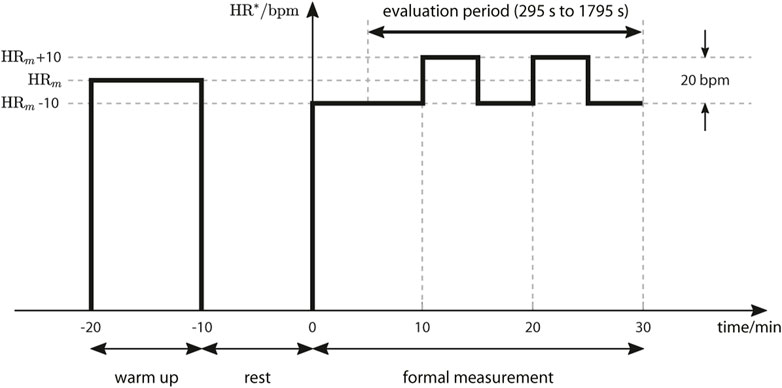
FIGURE 4. Test protocol: reference/target heart rate profile HR*.
During tests with the conventional HR controller, participants were instructed to maintain their position close to a location clearly marked at the sides of the treadmill track. For self-paced HR control, the reference distance x∗ was set individually to place each participant approximately at the same marks: for participants P01, P02, P03 and P04, x∗ was set to 0.7 m, 0.7 m, 0.4 m and 0.6 m, respectively.
For the self-paced HR control system, the reference/target running speed
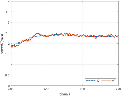
FIGURE 5. Illustrative screen display for the self-paced HR control system. The blue dashed line is the reference/target runner speed
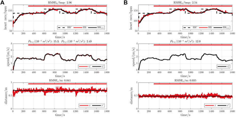
FIGURE 6. Illustrative measurements for participant P01. In each figure, the upper plot shows the reference heart rate (HR*, black dashed line), the measured heart rate (HR, red line) and the nominal/simulated heart rate response (HRsim, black line). The middle plots show the control signals, comprising the output from the HR compensator (
2.2.2 Equipment
All tests were carried out on a PC-controlled treadmill (model Venus, h/p/cosmos Sports & Medical GmbH, Germany; Figure 1B). The control algorithms were implemented using Simulink Desktop Real-Time (The MathWorks, Inc., USA) running on the PC.
Heart rate was monitored using a chest strap sensor (H10, Polar Electro Oy, Finland) and transferred to the PC via Bluetooth at a rate of 1 Hz. For both controller setups, the HR compensator Ch ran at a sample rate of 0.2 Hz (sample interval 5 s). Hence, the HR measurement was downsampled by averaging every five consecutive values.
The distance x was measured by a wire draw encoder (Ecoline BCG08-L1KM03PP, Sick AG, Germany) mounted at the front of the treadmill and connected to the runner via a side release buckle attached to a waist belt. The analogue output of the encoder was sampled in real time at 10 Hz using a data acquisition card (PCIe-6321, National Instruments Corp., USA) linked to the Simulink model. The distance compensator Cd also ran at a rate of 10 Hz.
2.2.3 Outcome measures
Heart rate tracking accuracy for both conventional and self-paced HR control was evaluated using the root-mean-square error (RMSE) between the HR measurement and the nominal, simulated HR response,
where HRsim is the simulated overall closed-loop HR response (HRsim = Tcl⋅HR*), HR is measured heart rate, and N is the number of discrete sample instants of HR measurement over the evaluation period. Since the sample interval for HR control was 5 s and the evaluation duration was 1500 s, N = 301.
For heart rate control, the intensity of the control signal (speed output
where v∗ denotes the control signal: for the conventional HR control system, v* represents
For the distance compensator, applied within the self-paced HR control structure, the intensity of the control signal (commanded treadmill speed output
Since the sample rate for the distance compensator was 10 Hz, N = 15001.
For distance control, tracking accuracy was evaluated by the RMSE between the measured distance and the reference distance,
where x∗ is the constant reference distance, x is the measured distance and N = 15001. Distance tracking accuracy was evaluated in this way for both self-paced HR control and for conventional HR control; in the latter scenario, since the distance controller was not active, but participants were instructed to remain close to a marked position, the reference variable x* in Eq. 21 was set to the mean distance observed during the evaluation period.
3 Results
A representative set of results for one participant (P01) is shown in Figure 6: this participant was chosen for illustration because heart rate tracking accuracy RMSEh was closest to the mean observed value for both self-paced and conventional HR control.
Individual outcomes, and averages pooled across all four participants, are shown in tabular form in Table 1 and graphically in Figure 7.
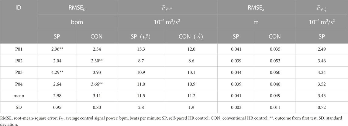
TABLE 1. Individual outcomes for two HR control systems.
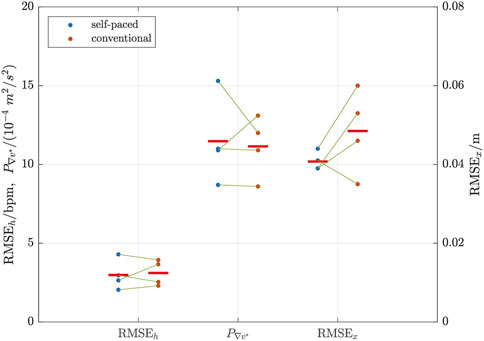
FIGURE 7. Comparison of outcomes for self-paced (left columns of blue dots) and conventional (right columns of red dots) HR control. The green lines link the pairs of samples for each individual participant. The left y-axis is for RMSEh and
Overall, mean HR tracking accuracy was slightly better (4% lower RMSEh) for self-paced control: RMSEh was 2.98 bpm ± 0.95 bpm (mean ± standard deviation) vs 3.11 bpm ± 0.80 bpm (self paced vs conventional). Of the four pairs of tests, self-paced was better in two cases while conventional was better in two cases, whereby it was observed that the second test for each participant always had the lowest RMSEh.
Self-paced control was also slightly more dynamic (3% higher
The self-paced system was found to have substantially better distance control accuracy (16% lower RMSEx) than the volitional distance control approach used during conventional HR control: RMSEx was 0.041 m ± 0.003 m vs 0.049 m ± 0.011 m (self paced vs conventional).
4 Discussion
The principal aim of this work was to assess the technical feasibility of a novel self-paced heart rate control strategy and to compare its accuracy with conventional heart rate control.
Experimental evaluation with four participants showed that the approach is technically feasible, since all participants were able to accurately follow the target running speed calculated by the HR compensator and presented to them visually. As a consequence, for all four participants, self-paced HR tracking accuracy was not substantially different from conventional HR control performance.
It was found, on average, that the self-paced heart rate controller gave slightly better performance than conventional HR control, with lower mean RMS tracking error RMSEh associated with higher mean average control signal power P∇. In the self-paced approach, the distance controller is embedded within the heart rate control loop in a classical nested-loop structure: this approach is known to work well when the inner loop works much faster than the outer loop such that deviations in the controlled variable of the inner loop—in this case, the actual runner speed—are corrected before they can have any substantial effect on the main controlled variable—in this case, heart rate. These conditions were fulfilled in the present work since the bandwidth of the input sensitivity function for the distance control loop was set to 2 Hz, which is approximately two decades higher than the 0.01 Hz bandwidth of the heart rate loop.
The results demonstrated a definite order-of-presentation effect since the second test for each participant had lower heart rate RMS tracking error; this was despite participants having been familiarised with the treadmill and experimental procedures prior to formal testing. This phenomenon was however addressed a priori by the counterbalanced experimental design—test order, i.e., SP then CON vs CON then SP, was changed for each participant—and the choice of an even number (four) of participants.
The novel design approach for the distance compensator, which optimised the shape of the input sensitivity function, was found to deliver highly accurate position control with mean RMS tracking error of 0.041 m, meaning that most of the observed position data points lay within just 4.1 cm of the reference distance (actually, about two thirds of the sample, since RMSEx in Eq. 21 is just the uncorrected standard deviation of the error sample). Moreover, the distance compensator output
The position controller design that was tested in the present work was based on an assumption of a frequency band for normal running cadence, and therefore for the position disturbance term dd, of 2.5 Hz–3.0 Hz. If the system were to be applied to patients who have some walking/running impediment, it may be necessary to increase this band to encompass lower frequencies. If necessary, this would involve shifting the four frequency response target points (Figure 3) to lower frequencies and/or lower magnitudes and recalculation of the controller parameters.
For position measurement, we employed a tethered approach involving physical connection of the runner to a wire-draw encoder, but, in principle, any other measurement system capable of delivering accurate, real time position information is compatible with the proposed self-paced strategy; for example, our experimental setup also allows non-tethered position control using an ultrasound sensor (Figure 1B).
5 Conclusion
The proposed self-paced heart rate control strategy with embedded automatic position control is deemed feasible: as noted in the Introduction, previous studies of conventional heart rate control have reported a tracking accuracy (RMSE) of about 2–3 bpm (Hunt and Fankhauser, 2016; Wang and Hunt, 2021a). Against this baseline, the average RMSE for self-paced heart rate control found here, viz. 2.98 bpm, is reasonable.
This approach may be helpful for people with gait impairments or other limitations that make it difficult for them to follow an imposed treadmill speed. However, since our experimental evaluation included only healthy participants, future research should evaluate the system’s performance in target populations of individuals with significant impairments and, if necessary, explore whether the frequency-domain specifications of the feedback design need to be adapted.
Data availability statement
The raw data supporting the conclusions of this article will be made available by the authors, without undue reservation.
Ethics statement
This research was performed in accordance with the Declaration of Helsinki. The study was reviewed and approved by the Ethics Committee of the Swiss Canton of Bern (Ref. 2019-02184). The patients/participants provided their written informed consent to participate in this study. Written informed consent was obtained from the individual(s) for the publication of any potentially identifiable images or data included in this article.
Author contributions
HW and KH contributed to the conception and design of the study. HW did the data acquisition. HW and KH contributed to the analysis and interpretation of the data. HW wrote the manuscript and KH revised it critically for important intellectual content. Both authors read and approved the final manuscript.
Funding
This work was supported by the Swiss National Science Foundation (Grant Ref. 320030-185351).
Conflict of interest
The authors declare that the research was conducted in the absence of any commercial or financial relationships that could be construed as a potential conflict of interest.
Publisher’s note
All claims expressed in this article are solely those of the authors and do not necessarily represent those of their affiliated organizations, or those of the publisher, the editors and the reviewers. Any product that may be evaluated in this article, or claim that may be made by its manufacturer, is not guaranteed or endorsed by the publisher.
References
Almeida, Q. J., and Bhatt, H. (2012). A manipulation of visual feedback during gait training in Parkinson’s disease. Parkinson’s Dis. 2012, 1–7. doi:10.1155/2012/508720
Åström, K. J., and Murray, R. M. (2008). Feedback systems. Princeton (USA) and Oxford (UK): Princeton University Press.
Diaz, J. M., Costa-Castello, R., and Dormido, S. (2019). Closed-loop shaping linear control system design. IEEE Control Systems Magazine, 58–74.
Hunt, K. J., Anandakumaran, P., Loretz, J. A., and Saengsuwan, J. (2018). A new method for self-paced peak performance testing on a treadmill. Clin. Physiology Funct. Imaging 38 (1), 108–117. doi:10.1111/cpf.12390
Hunt, K. J., and Fankhauser, S. E. (2016). Heart rate control during treadmill exercise using input-sensitivity shaping for disturbance rejection of very-low-frequency heart rate variability. Biomed. Signal Process. Control 30, 31–42. doi:10.1016/j.bspc.2016.06.005
Ibala, E., Coupaud, S., and Kerr, A. (2019). Comparison of the muscle pattern variability during treadmill walking (fixed and self-pace) and overground walking of able-bodied adults. J. Ann. Bioeng. 1, 47–55.
Kim, S., Roh, J., Hyeong, J., Yang, G., and Kim, Y. (2017). Dynamic stability on nonmotorized curved treadmill: Self-paced speed versus fixed speed. Int. J. Precis. Eng. Manuf. 18 (6), 887–893. doi:10.1007/s12541-017-0105-5
Kwakernaak, H. (1993). Robust control and H∞ optimization—Tutorial paper. Automatica 29 (2), 255–273. doi:10.1016/0005-1098(93)90122-a
Levin, I., Lewek, M. D., Feasel, J., and Thorpe, D. E. (2017). Gait training with visual feedback and proprioceptive input to reduce gait asymmetry in adults with cerebral palsy: A case series. Pediatr. Phys. Ther. 29 (2), 138–145. doi:10.1097/pep.0000000000000362
Liu, L. Y., Sangani, S., Patterson, K. K., Fung, J., and Lamontagne, A. (2020). Real-time avatar-based feedback to enhance the symmetry of spatiotemporal parameters after stroke: Instantaneous effects of different avatar views. IEEE Trans. Neural Syst. Rehabilitation Eng. 28 (4), 878–887. doi:10.1109/tnsre.2020.2979830
Plotnik, M., Azrad, T., Bondi, M., Bahat, Y., Gimmon, Y., Zeilig, G., et al. (2015). Self-selected gait speed-over ground versus self-paced treadmill walking, a solution for a paradox. J. NeuroEngineering Rehabilitation 12(20), 20–11. doi:10.1186/s12984-015-0002-z
Riebe, D., Ehrman, J. K., Liguori, G., and Magal, M. (Editors) (2018). ACSM’s guidelines for exercise testing and prescription. 10th ed. (Philadelphia, USA: Wolters Kluwer).
Robey, R. R. (2004). A five-phase model for clinical-outcome research. J. Commun. Disord. 37 (5), 401–411. doi:10.1016/s0021-9924(04)00039-5
Scheadler, C. M., and Devor, S. T. (2015). “VO2max measured with a self-selected work rate protocol on an automated treadmill.,” Med. Sci. Sports Exerc. 47 (10), 2158–2165. doi:10.1249/mss.0000000000000647
Sloot, L., Van der Krogt, M., and Harlaar, J. (2014). Self-paced versus fixed speed treadmill walking. Gait Posture 39 (1), 478–484. doi:10.1016/j.gaitpost.2013.08.022
Theunissen, K., Van Hooren, B., Plasqui, G., and Meijer, K. (2022). Self-paced and fixed speed treadmill walking yield similar energetics and biomechanics across different speeds. Gait Posture 92, 2–7. doi:10.1016/j.gaitpost.2021.11.005
Tobar, C., Martinez, E., Rhouni, N., and Kim, S.-J. (2018). The effects of visual feedback distortion with unilateral leg loading on gait symmetry. Ann. Biomed. Eng. 46 (2), 324–333. doi:10.1007/s10439-017-1954-x
Wang, H., and Hunt, K. J. (2021). Heart rate control using first-and second-order models during treadmill exercise. Syst. Sci. Control Eng. 9 (1), 651–662. doi:10.1080/21642583.2021.1976304
Wang, H., and Hunt, K. J. (2021). Identification of heart rate dynamics during treadmill exercise: Comparison of first- and second-order models. Biomed. Eng. OnLine 20 (37), 37. doi:10.1186/s12938-021-00875-7
Wiens, C., Denton, W., Schieber, M. N., Hartley, R., Marmelat, V., Myers, S. A., et al. (2019). Walking speed and spatiotemporal step mean measures are reliable during feedback-controlled treadmill walking; however, spatiotemporal step variability is not reliable. J. Biomechanics 83, 221–226. doi:10.1016/j.jbiomech.2018.11.051
Keywords: heart rate dynamics, heart rate control, treadmill, real-time feedback, self-paced
Citation: Wang H and Hunt KJ (2023) Self-paced heart rate control for treadmill exercise. Front. Control. Eng. 4:1158164. doi: 10.3389/fcteg.2023.1158164
Received: 03 February 2023; Accepted: 23 February 2023;
Published: 09 March 2023.
Edited by:
Ramon Vilanova, Autonomous University of Barcelona, SpainReviewed by:
Asier Ibeas, Autonomous University of Barcelona, SpainG. Lloyds Raja, National Institute of Technology Patna, India
Copyright © 2023 Wang and Hunt. This is an open-access article distributed under the terms of the Creative Commons Attribution License (CC BY). The use, distribution or reproduction in other forums is permitted, provided the original author(s) and the copyright owner(s) are credited and that the original publication in this journal is cited, in accordance with accepted academic practice. No use, distribution or reproduction is permitted which does not comply with these terms.
*Correspondence: Hanjie Wang, aGFuamllLndhbmdAYmZoLmNo