 Nikos Chrisochoides1*
 Yixun Liu1
 Fotis Drakopoulos1
 Andriy Kot1
 Panos Foteinos1Christos Tsolakis1Emmanuel Billias1Olivier Clatz2
 Nicholas Ayache2
 Andrey Fedorov1,3
 Alex Golby3,4Peter Black4Ron Kikinis3
- 1Center for Real-Time Computing, Computer Science Department, Old Dominion University, Norfolk, VA, United States
- 2Inria, French Research Institute for Digital Science, Sophia Antipolis, Valbonne, France
- 3Neuroimaging Analysis Center, Department of Radiology, Harvard Medical School, Boston, MA, United States
- 4Image-guided Neurosurgery, Department of Neurosurgery, Harvard Medical School, Boston, MA, United States
This paper compares three finite element-based methods used in a physics-based non-rigid registration approach and reports on the progress made over the last 15 years. Large brain shifts caused by brain tumor removal affect registration accuracy by creating point and element outliers. A combination of approximation- and geometry-based point and element outlier rejection improves the rigid registration error by 2.5 mm and meets the real-time constraints (4 min). In addition, the paper raises several questions and presents two open problems for the robust estimation and improvement of registration error in the presence of outliers due to sparse, noisy, and incomplete data. It concludes with preliminary results on leveraging Quantum Computing, a promising new technology for computationally intensive problems like Feature Detection and Block Matching in addition to finite element solver; all three account for 75% of computing time in deformable registration.
1. Introduction
Cancer continues to be a significant cause of death in the USA and worldwide. The number of Americans with brain tumors is about one million, and about 100,000 will receive a primary brain tumor diagnosis in 2023 (1). Neurosurgical resection is a standard and effective treatment for brain tumor patients. Removing as much of the tumor as possible is imperative to ensure the best results while preserving healthy brain structures. This approach can extend the progression time while reducing symptoms and seizures.
One of the main challenges in neurosurgery is identifying critical areas of the brain responsible for essential functions, such as the motor cortex. These areas are unique to each patient and cannot be located with the naked eye. However, medical imaging has proven to be an asset in overcoming this hurdle. Over the past two decades, advancements in image-guided therapy (2) have allowed surgeons to utilize preoperative imaging (3) for neuronavigation. With visualization (4) and quantitative analysis software systems (5), surgeons can safely remove tumors, such as gliomas, from sensitive brain areas. These advancements have significantly improved neurosurgery's safety and success rates.
Before surgery, a combination of anatomical Magnetic Resonance Imaging (MRI) and functional MRI (fMRI) can pinpoint crucial brain areas that affect functions such as vision, speech and language, or motor control. Moreover, Diffusion Tensor Imaging (DTI) can map out white matter tracts that connect to these essential regions and are located near or through the tumor. These imaging techniques are essential in ensuring the precision of the tumor removal procedure.
During surgery, the opening of the skull and dura causes changes in pressure inside the Intra-Cranial Cavity. Because of this and other factors, such as cerebrospinal fluid drainage and gravity's effect, the brain changes its shape, introducing discrepancies in relation to the pre-operative configuration. The adoption of intraoperative MRI (iMRI) has provided a means for monitoring brain deformation (or brain shift) during surgery (6). Figure 1 depicts the preoperative and interoperative MRI data before and during brain tumor resection. The number of hospitals offering iMRI has grown over the past decade from a handful of research centers to hundreds of clinical sites worldwide (7). Although acquiring fMRI and DTI during surgery may not be feasible, the preoperative images can be aligned with an iMRI through non-rigid registration. The registration results could be applied to preoperative fMRI and DTI, offering more accurate and updated guidance to the neurosurgeon (8). Deformable transformation use on fMRI and DTI is beyond the scope of this paper. This study evaluates deformable registration accuracy between pre-op MRI and intra-op MRI.
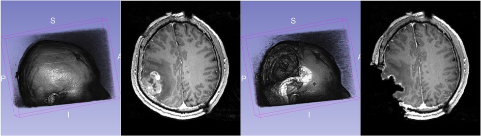
Figure 1. Discrepancies between preoperative and intraoperative MRI before and during neurosurgery: volume rendering and axial view. Preoperative MRI (left) and intraoperative MRI (right) are acquired after a substantial part of the tumor is removed.
2. Background
Image registration, in general, is concerned with the spatial alignment of corresponding features in two or more images. During image registration, a spatial transformation is applied to one image (called floating) to be brought into alignment with the fixed or target image, which is used as a reference position of the object (patient's brain). In the registration process, the floating image corresponding to the pre-operative MRI is aligned with the patient's position using Rigid Registration (RR), a global transformation. Then, physic-based non-rigid registration (PBNRR) uses spatially varying (i.e., local) transformation to account for brain shift, which drastically varies in different brain locations (9). Image registration algorithms generally optimize specific similarity criteria between the fixed and floating image under varying spatial transformation parameters. The computational complexity of this optimization depends on the number of parameters that describe the transformation.
Figure 2 depicts a flowchart with all steps and software modules for pre- and intra-operative image processing for image-guided neurosurgery at Brigham and Women's Hospital (BWH) in Boston, MA. The intra-operative images were 0.5 T iMRI (11) and acquired during surgery at BWH, since then the facility is upgraded and currently using more advanced intraoperative devices (12). The patient-specific Finite Element (FE) model, selection of registration points, and non-rigid registration took place remotely at the Center for Real-Time Computing (CRTC) in Virginia using a midsize High-Performance Computing (HPC) cluster of workstations (10).
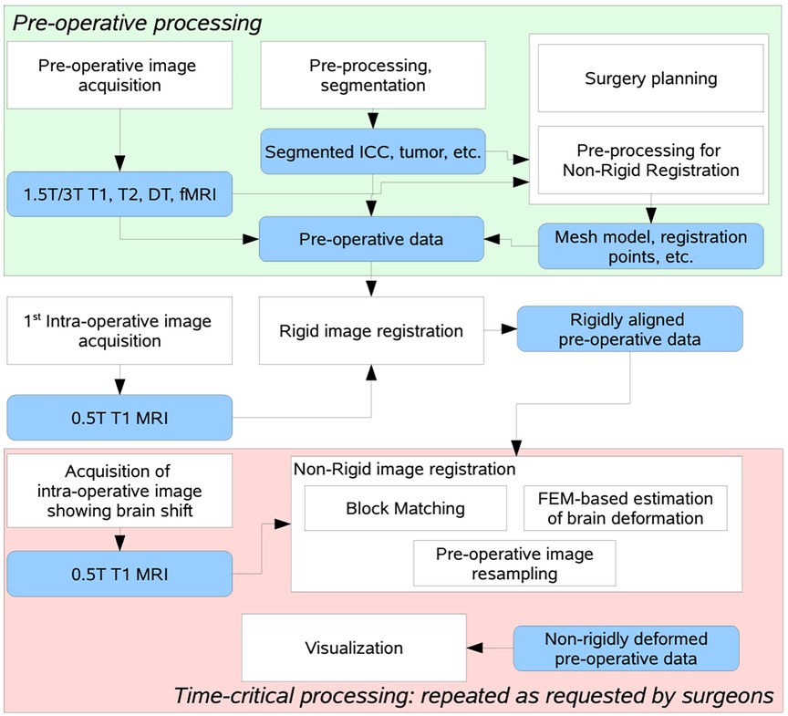
Figure 2. Flow diagram of the NRR process used in BWH during a clinical study, after decoupling the non-rigid registration software to manage fault-tolerance of the distributed computation process (10).
We first introduce Clatz et al.'s non-rigid registration technique from 2005. Then, we delve into two enhancements that aim to increase its precision when working with sizable brain tumors. The focus is on the elimination of outliers of both points and elements. Outliers emerge from tissue removal in the case of large brain tumors, described in detail by Liu et al. (13) and Drakopoulos et al. (14). We won't delve into previous research by other groups, in particular reviews or comparisons like Sotiras et al. (15), who conducted a comprehensive survey and taxonomy of NRR methods, and Frisken et al. (16), who presented a clinically insightful review at the B-Splines and FE-based methods. Finally, this comparison is meant to complement a companion review of HPC software implementation-related aspects for the same methods, and it will appear in Chrisochoides et al. (17).
3. Physics-based non-rigid registration
The specific NRR method was initially developed in INRIA, France, by Clatz et al. (9) and is implemented as open-source software by the CRTC group in Virginia, USA (18). It is designed for registering high-resolution pre-operative data with iMRI—the NRR process takes place in two phases: preoperative and intra-operative. The intra-operative computation is initiated when a scan shows the shift of the brain. The basic idea of the registration method is to estimate the sparse deformation field that matches “similar” locations in the pre-operative and iMRI and then use a biomechanical model for brain deformation to discard unrealistic displacements so that it can derive a dense deformation field that defines a transformation for each point in the image space.
Sparse displacement vectors are obtained at the selected points in the image, where the intensity variability in the surrounding region exceeds a certain threshold. Such registration (or feature) points can be identified before the time-critical part of the computation in the floating (pre-operative) image. Once the reference (intra-operative) scan is available, the deformation vector is estimated at each of the selected points utilizing block matching (9), where fixed-size rectangular regions (blocks) centered at the registration points are identified in the floating image. Given such a block, the method selects a search region (window) in the reference (or fixed) image. At the registration point, the vector of the sparse deformation field is defined by the block's displacement, which produces the most significant similarity between the image intensities in the block and the overlapping section of the window. The normalized cross-correlation similarity metric is used.
It is worth noticing the high computational complexity of the block-matching procedure. Considering the sizes of three-dimensional block and window are defined in pixels as B = {Bx, By, Bz} and W = {Wx, Wy, Wz}, then the bound on the number of operations is O(BxByBz × WxWyWz), for a single registration point.
The registration is an energy minimization problem (9). One seeks the balance between the external forces, proportional to the sparse displacements, and the internal forces of the mesh resisting deformation:
where K is the mesh stiffness matrix, H is the linear interpolation matrix form the matches to the displacements at mesh vertices, S is the block matching stiffness matrix (matches with higher confidence are assigned higher weights), D is the vector for the block displacements, and U is the unknown displacement vector for mesh vertices. The stiffness matrix, K, is calculated based on the assumed physical properties of the brain tissue elastic modulus E and Poisson ratio ν. This formulation can tolerate some outliers but suffers from a systematic error concerning the correctly estimated displacements. Alternately, one can use approximation to compute the locations of vertices, which would minimize the error concerning the block matches:
However, this formulation would also minimize displacement error regarding outlier measurements, which one would like to eliminate from the set of block displacements. A robust iterative approach combines approximation and interpolation. Gradual convergence to the interpolation solution is achieved using the external force F added to the formulation (1) to slowly relax the internal mesh stress:
Rejection of the outlier matches is done iteratively, with a user-defined total percentage of matches to be discarded, fR, and the number of rejection iterations, nR, as follows:
1: INPUT: nR, fR
2: for i = 0 to nR do
3: Fi ⇐ KUi
4: Ui + 1 ⇐ [K + HT SH]−1[HT SD + Fi]
5: for all blocks k do
6: compute error function ξk
7: end for
8: reject fR/nR blocks with the highest error
9: re-compute S, H, D
10: end for
11: repeat
12: Fi ⇐ KUi
13: Ui+1 ⇐ [K + HT SH]−1[HT SD + Fi]
14: until convergence
The force, F, is computed at each iteration to balance the internal force of the mesh, KUi. The error, ξk, measures the difference between the block displacement approximated from the current deformed mesh and the matching target for the kth block. The user-defined percentage of the displacements with the highest ξk values is rejected. This method converges to the formulation in (2) and is simultaneously tolerant to most point outliers due to faulty matching. However, large brain shifts due to tumor resection with drastic changes in the geometry, the fixed (iMRI) creates element outliers that need to be considered and we address in Section 4.
4. Nested expectation maximization method
This section summarizes an extension of the PBNRR by identifying and removing additional type (element) outliers due to tissue resection using the Nested Expectation and Maximization method, referred to as NEMNRR (13). The NEMNRR method formulates the registration as a three-variable (point correspondence, deformation field, and resection region) functional minimization problem, in which point correspondence is represented by a fuzzy assign matrix; the deformation field is represented by a piece-wise linear function regularized by the strain energy as in PBNRR (9), but this time extends the model from a single homogenous tissue to a heterogeneous multi-tissue based biomechanical model. A Nested Expectation and Maximization framework is developed to resolve these three variables simultaneously (13).
The NEMNRR method extends the cost function used in Clatz et al. (9) to:
where the continuous domain Ω (brain image) is discretized as a multi-tissue mesh M using the method presented in Liu et al. (19, 20) on a multi-label image segmented from the pre-operative MRI. MRem is the removed mesh approximating the resection region . is the element stiffness matrix of element ei. Each element is associated with a tissue label, which determines the elastic parameters to build the element stiffness matrix. The first term of Equation (4) approximates the strain energy as in Clatz et al. (9), and the third term approximates the volume of the resection region, in which is the volume of element ei. In the second term, the entries of the vector D are defined as
Considering the registration problem in the Expectation and Maximization (EM) context (21), cost function (4), from the probability (Bayesian) point of view, defines the likelihood function, in which the unknown (model parameter) is the displacement vector U, and the missing data are the correspondence C and the resection region MRem. Assuming MRem is known, the more accurate the estimate of C, the more accurate the estimate of U, and vice versa. EM algorithm is very efficient for this kind of circular dependence problem, so one employs EM to solve U and C under a specified MRem. To resolve MRem, one can treat U and C as an approximately known pair U, C. MRem is approximated by a collection of tetrahedra located in a region of the model, which corresponds to the resection region in the intraoperative MRI. MRem is initialized to and updated at each iteration of the outer EM. The outer EM stops if all the tetrahedra contained in the resection region are collected, as shown in Figure 3.
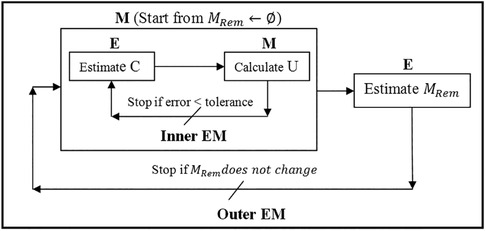
Figure 3. Nested expectation and maximization framework. This figure adopted from Liu et al. (13), Figure 3.
The resection region is difficult to identify in the intra-operative MRI, so a simple threshold segmentation method is used. We cannot determine if a tetrahedron is an outlier based solely on its position. It might be in the background image (BGI) instead of the resection region. To ensure the element outlier rejection algorithm is robust, we use the fact that the resection region is made up of tetrahedra that not only fall in the BGI of intra-operative MRI but also connect and form a maximal connected submesh. The outliers are collected iteratively, with additional outliers added into MRem if they fall in the BGI and connect with the maximal simply connected submesh identified in the previous iteration. We demonstrate the NEMNRR strategy in Figure 4, with the inner EM iterating horizontally and the outer EM iterating vertically.
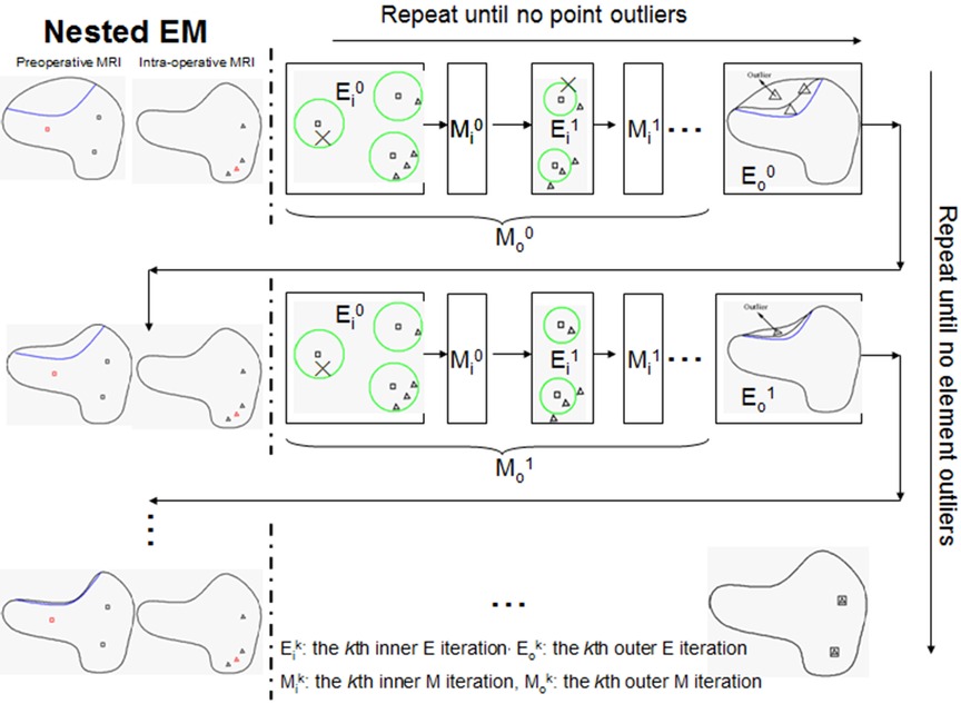
Figure 4. Illustration of nested expectation and maximization strategy. Row: inner EM, Column: outer EM. This figure adopted from Liu et al. (13), Figure 4.
NEMNRR addressed a fundamental challenge in PBNRR: “pre-operative landmarks near the tumor fail to correspond to iMRI landmarks”. The crux of the idea is to use the NEM method to resolve the deformation field with missing correspondence, specifically in the resection region. This has many implications; one is to compute the registration error more accurately than Hausdorff Distance (HD) when correspondence is unknown. Like the PBNRR, the NEMNRR uses the strain energy of the biomechanical model to regularize the solution. Figure 5 shows the results of point outlier rejection produced by NEMNRR; compared to the edges before outlier rejection, most point outliers are removed from pre-MRI and iMRI after outlier rejection.
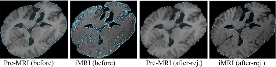
Figure 5. Point outlier rejection. Two left-most pre-op and iMRI depict (in blue) all edges detected before rejecting outliers, while the right-most figures depict the remaining edge points after outlier rejection.
5. Comparison of outlier rejection schemes
In Sections 5.1, 5.2, we compare two approximation-based outlier rejection methods. Then, in Section 5.3, we compare them with a geometry-based method using 9 cases from earlier studies.
5.1. PBNRR rejection scheme vs. rigid registration
First, we compare the PBNRR outlier rejection scheme against state-of-the-art Rigid Registration and B-Splines interpolation schemes with no rejection of outliers. We use five cases from NCIGT (22); they were first presented by Archip et al. (8) with additional analysis by Liu et al. (23). Table 1 lists the patient information, including the gender, tumor location, and histopathology. They are revisited for completeness and reviewed regarding the impact of the outlier rejection scheme on registration accuracy and execution time.

Table 1. Patient information from Liu et al. (23).
The PBNRR (9) and its implementation in Liu et al. (18, 23) uses a homogeneous model, i.e., a single mesh in the FE model. As reported in Table 2, the execution time is about a minute, and with an average single heterogeneous HPC workstation (with a moderate number of 20 cores and a single GPU, the registration time can be reduced to less than a minute. See Liu et al. (18) for a detailed analysis.
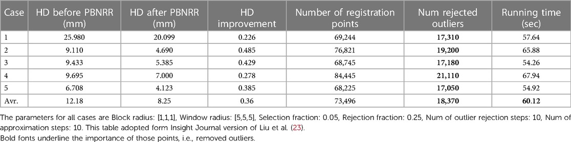
Table 2. The quantitative results for the 5 cases are obtained by running the PBNRR on a single homogenous mesh (using 8 threads).
Table 2 indicates that out of about 73 K registration points, the PBNRR rejects about 18 K as outliers. A detailed study of 30 cases by Drakopoulos et al. (24) indicates this leads to a moderate (about 1.5 mm) improvement over the accuracy of the rigid registration and not a clear advantage over the B-Splines approximation scheme implemented in ITK and Slicer3D when accuracy is measured in terms of HD. A recent evaluation (24) from expert neurosurgeons (using specific brain landmarks) indicates that the accuracy of the PBNRR rejection scheme improves the max (and mean) average accuracy to 6.8 (and 3.4) mm from to 8.9 (and 5.6) mm 8.3 (and 4.4) mm by Rigid Registration1 and B-Splines2, respectively. Overall, the PBNRR3 outlier rejection scheme improves the registration accuracy between 1 mm and 2 mm from two state-of-the-art rigid registration schemes.
The end-to-end execution time for registering preoperative to intraoperative images for all 30 cases. Rigid registration, B-Spline, and PBNRR required, on average, 0.84, 8.98, and 0.83 min, respectively (including I/O). The B-Spline method (with comparable accuracy) is the most computationally intensive, requiring more than 8 min in 17 out of 30 cases (24). A different set of B-Spline parameters, such as a smaller sampling percentage, a smaller number of histogram bins, or a coarser grid (than the 15 × 15 × 15 grid used in this study), could improve B-Spline performance at the cost of accuracy.
5.2. NEMNRR vs. PBNRR rejection scheme
To compare the two outlier rejection schemes between the NEMNRR and PBNRR, we use three cases from NCIGT (22) and two additional cases from Huashan Hospital (HH) with very large brain shifts. Table 3 lists (the first case from Table 1 and the remaining four cases from an earlier study by Liu et al. (13) the patient information such as gender, tumor location, and histopathology. The thickness slice varies between 1 mm, 1.3 mm, and 2 mm for pre-op MRIs and 1 mm, 2 mm, and 2.5 mm for iMRI. The matrix varies even more, a detailed description is presented in Drakopoulos et al. (24).
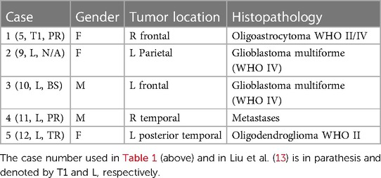
Table 3. Patient information of five cases for the comparison of PBNRR vs. NEMNRR.
Given that NEMNRR is designed to improve registration accuracy using a multi-tissue FEM model, we employ the same multi-tissue mesh in both methods to measure the influence of the outlier rejection scheme on the registration. We build a simple two-tissue mesh (ventricle + the rest of the brain) to minimize the influence of the discrepancy of the geometry and topology between single mesh and multi-tissue mesh. In the homogeneous model, we use Young's modulus = 3,000 Pa, Poisson's ratio = 0.45 for all tetrahedra, and in the heterogeneous model, we replace Young's modulus with 10 Pa and Poisson's ratio with 0.1 for the ventricle (25).
We have seen that, on average, the PBNRR rejects about 18 K outliers out of 73.5 K registration points (approximately 24%) and takes about a minute to complete the registration for an FE-mesh with about 40 K to 50 K elements. Table 4 indicates that for similar cases (see Table 3), the NEMNRR removes 48 K outliers out of 170 K registration points (approximately (28%) at quite a high cost; NEMNRR takes about six times longer to complete the registration.
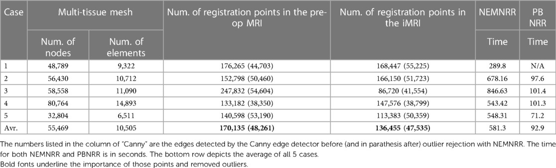
Table 4. Selective parameters for NEMNRR and PBNRR related to outlier rejection and execution time.
However, NEMNRR increases the accuracy by 9.92 mm on average at the registration points (i.e., the evaluation is performed on Canny edge points) and 2.40 mm when the evaluation is performed on the tumor or resection margin, depending on the case of brain shift or resection. All measurements are based on HD. In 2014, Liu et al. thoroughly compared PBNRR and NEMNRR.
To evaluate the accuracy, we rejected outlier registration points in pre-MRI and iMRI and calculated the HD before registration. Also, we rejected outlier registration points in iMRI and warped pre-MRI to calculate the HD after registration. The tumor boundaries in pre-MRI and iMRI are delineated to calculate the HD for brain shift cases. In each resection case, we choose the pre-MRI slice, in which the tumor is completely intra-operatively resected, so the margin corresponding to the resection margin of iMRI can be identified using the tumor boundary. The resection margin is delineated in iMRI, and directed HD is used for evaluation.
Using HD, the data in Table 5 suggest that NEMNRR and PBNRR do not perform well in the first case, a Partial Resection (PR). In the second case and around the tumor, it appears to be an improvement to about 1 mm. The remaining cases appear to have improved substantially. However, the evaluation results on edges and resection margins must be more consistent within the 1 mm tolerance. This is an area that needs to be studied further. Table 5 indicates that the NEMNRR multi-tissue (Single) reduces the error of Rigid Registration at the registration points from 14.10 mm to 2.5 (2.9) mm, but the evaluation on the resection margin shows the error is reduced only from 12.08 mm to 5.3 (5.6) mm. The reason for this is most likely that the detected edges, although well-aligned, are too far away from the tumor and the resection region and, thus, ineffective in driving the model to estimate the deformation around the resection margin. A larger number of cases (25) were analyzed and compared with both NEMNRR and PBNRR (13), indicating that the mean plus/minus standard deviation for HD between the pre-MRI and iMRI for RR, PBNRR, and NEMNRR is 17.48+/−0.2, 12.7+/−5.4, and 9.8+/−4.7, respectively.
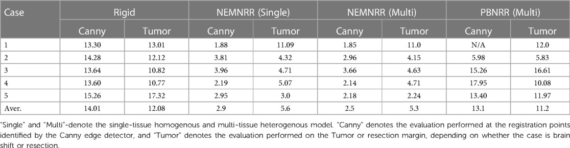
Table 5. Quantitative evaluation and comparison for 5 cases.
5.3. Comparison with a geometric scheme
In Drakopoulos et al. (14, 24), we used geometric means to remove outliers and attempt to improve the registration error for large tumor resections while staying within the time constraints imposed for clinical use (i.e., completion time 3–4 min). The Adaptive Non-Rigid Registration (ANRR) method gradually adjusts the mesh for the FEM model to an incrementally warped segmented iMRI as opposed to NEMNRR that iteratively rejects feature and element outliers derived from a single (original) segmented iMRI. The idea of the geometric approach is to remove slivers and potentially negative volume elements resulting from large deformation fields (sometimes larger than the size of the elements) computed by block matching. This is achieved through an incremental approximation to reach the end goal. The ANRR method improves the accuracy of the model by improving the accuracy of the basic numerical calculations involved at the cost of increasing (potentially) the overhead for the mesh generation step and substantially increasing the computational cost of the linear solver several times. However, even with a single HPC node (DELL workstation with 12 Intel Xeon X5690@3.47 GHz CPU cores and 96 GB of RAM), the ANRR execution time on average is less than two minutes (26), which is within the time constraints of the procedure in the operating room.
Table 6 indicates that a large fraction (about 60%) of time is spent in the parallel FEM Solver module, which includes assembling the system matrices and rejecting the feature (or point) outliers. The differences between the NEMNRR and ANRR are: (1) using different mesh generation methods and (2) treatment of element outlier rejection. In the case of ANRR, we used a Delaunay-based method presented by Foteinos et al. (27), while in NEMNRR, we used the BCC-based method presented by Liu et al. (20). As indicated in the evaluation of both meshing methods in Foteinos and Liu et al. (19, 28), the Delaunay-based method is 15 times faster than the BCC-based method (evaluated on the same set of cases and forced to achieve the same fidelity). However, the BCC-based method is about twice as effective (evaluated in terms of the convergence rate in the FEM-solver) than the Delaunay-based method.
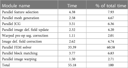
Table 6. Profile of the ANRR modules based on total (end-to-end) execution time (in seconds) and relative percentage (%) for each module and adapted from Table 4 (14).
The geometry-based treatment of element outliers (implemented with Parallel Feature Selection, Image Deformation Filed Update and Correction, and Warped pre-op Segmentation Correction presented in Drakopoulos et al. (14) along the real-time I2M conversion technologies like the Delaunay-based method presented in Foteinos et al. (27) to a degree addressed the computational slow-down of NEMNRR (about six times slower compared to PBNRR). It is worth noticing that the role of real-time I2M conversion is not because one needs large FE-meshes for this application, but the requirement is high fidelity and good quality meshes to be generated quickly.
Table 7 compares the PBNRR, NEMNRR, and ANRR (with the parameters for all three methods described in Table 9, Appendix I) with two publicly available registration methods: RR and B-Spline (with the parameters for both methods described in Table 10, Appendix I). This time, the comparison is based on two groups of (independent) experts from Europe [AHEPA Hospital in Greece and the results appeared in Drakopoulos et al. (24)] and Asia [Huashan Hospital in China and the results appeared in Liu et al. (13)]. This Table presents each case's minimum, maximum, and mean errors. The assessment confirms that a combination of the Clatz et al. point outlier rejection scheme with the removal of element outliers by alternating PBNRR approximation with remeshing can improve the accuracy of the registration: from an average max (mean) error of 8.4 (4.3) mm achieved by PBNRR to 6.5 (3.2) mm for ANRR as opposed to 7.7 (3.6) mm for NEMNRR.
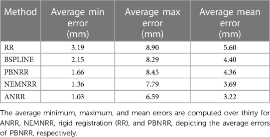
Table 7. Quantitative registration results used six anatomical landmarks for 30 (24) and 25 (13) cases.
To summarize, it is important to note that neither the HD metric nor expert evaluation can be reliably reproduced due to a lack of robustness, and the possibility of human error in expert evaluation. Therefore, combining the two approaches (as we have observed that human error can be caught and corrected using HD results) is the safest way forward until the research community develops more robust and automatic metrics to measure registration accuracy.
6. Open problems
6.1. Problem I: non-rigid registration error estimation
The evaluation methodology of the analysis we presented in this paper used two methods: (1) expert evaluation (see Table 7), but prone to human errors, and (2) automatic method (30) relying on HD to evaluate the registration accuracy because it is fast and does not require manual intervention (see Tables 2, 5). The automatic method relies on Canny edge detection (31) to compute two-point sets. The first point set is computed from the preoperative volume and then transformed (using the deformation field computed by each registration method) from the preoperative to the intraoperative space. The second point set is computed from the intraoperative volume. An HD metric (32) was employed to calculate the degree of displacement between the two-point sets. This approach helps compare the impact of the different approximation schemes. However, it gives an upper bound on the error and does not consider the correspondence between the two-point sets. We hope that the NEMNRR method, the way it is formulated, can provide (in the future) a way to compute the correspondence between those two sets of points, making HD error much more reliable.
6.2. Problem II: registration point distribution into FE-Mesh elements
One of the requirements we have yet to make much progress on is the suboptimal distribution of the effective registration points, i.e., once perceived outliers are rejected. This problem concerns mesh elements, and a very small number (same cases zero) of points makes the numerical formulation more sensitive to outliers and introduces additional displacement error due to integral voxel displacements recovered by block matching. The distribution of points also influences the condition of the [K + HTSH] matrix.
Over the last 15 years, we developed three different Image-to-Mesh (I2M) conversion methods for medical applications: (i) Body-Centered Cubic (BCC) was proposed by Molino et al. (33) and was implemented by Fedorov et al. (34) for a single-tissue and it was initially used in PBNRR (8). Then, a multi-tissue capability was used by Liu et al. (19, 20), and it was used in NEMNRR (13) and mesh gradation (i.e., control mesh size to reduce without compromising the fidelity of the mesh) by Drakopoulos et al. (35); (ii) Delaunay-based (27), and it is used in real-time ANRR with the results presented in Drakopoulos et al. (14, 24) and in Table 7; (iii) Lattice Decimation methods (36) because the relatively dense initial BCC mesh captures the object surface without much compression, thus preserving the good angles of the BCC triangulation. All three methods developed and evaluated for this project need further development regarding topologic accuracy in the presence of multi-tissue models. For example, one important question is: “How many materials can be accurately reconstructed around a mesh vertex or an edge so that the multi-tissue mesh is a topologically accurate representation of the input data?”
We have been working on yet another open question that involves generating meshes while considering the registration points recovered through the block-matching step. To our knowledge, no existing method in the literature addressed this question. Although we have made some progress, much work still needs to be done in this area. In Fedorov et al. (37), we attempted to improve the distribution of registration points over the mesh, using custom sizing functions for two different mesh generation methods (Delaunay refinement and Advancing Front). The evaluation was based on synthetic deformation fields and showed that the limited success of registration point equidistribution might reduce the registration error.
For completeness, a summary of the method employed in Fedorov and Chrisochoides (29) is presented along with the modifications that can turn it into an anisotropic metric-based method. The (sub-)optimal distribution of the registration points can be formulated as assigning approximately the same number of registration points at each mesh vertex cell complex, where a mesh vertex cell complex is defined as the set of all the elements attached to a vertex. See, for example, Figure 6, left: the p1, p2, and p3 vertex cells on the left have 3, 7, and 5 landmarks, respectively. In Figure 6, right: by collapsing edge p2p1, one attempts to equidistribute the landmarks. Both the vertex cells of p1 and p2 now have seven landmarks.
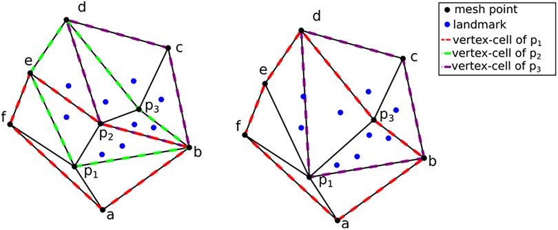
Figure 6. Optimizing landmark distribution.
The crux of the method is to set the local spacing at each vertex equal to the distance to the k-th closest registration point. Assuming an ideal spacing, each vertex's mesh vertex cell complex will contain k registration points. An illustration for k = 5 is given in Figure 7 left. Notice that another way to interpret the sizing constraint at each vertex is using a sphere centered at each mesh vertex with a radius equal to the distance to the k-th registration point.
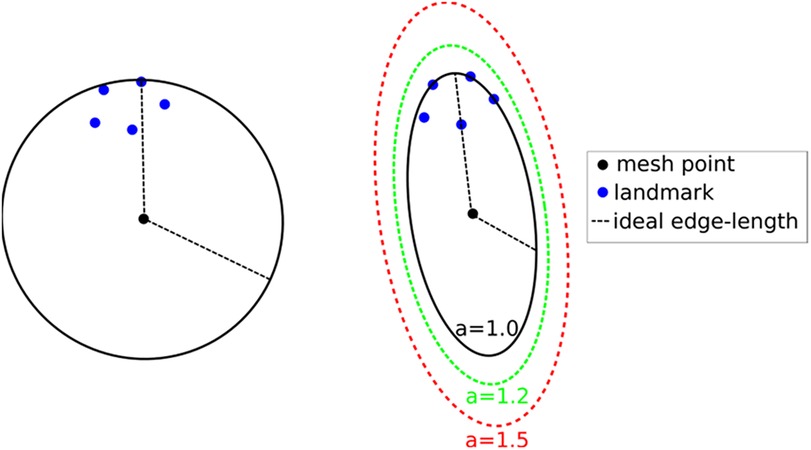
Figure 7. Left: isotropic metric that sets the spacing equal to the distance of the fifth closest registration point. Right: Anisotropic metric based on the five registration points for different values of the inflation constant. This Figure adapted from Drakopoulos et al. (24), Figure 5.
This technique produces adaptive meshes but does not efficiently capture the local distribution of landmarks. This is because only the k-th point is used, and the relative positions of the other k-1 landmarks are disregarded. To improve this, one can substitute the spheres at each vertex with the smallest bounding ellipsoid that encompasses the k closest registration points and is centered at the vertex. Describing the local spacing as an ellipsoid gives the ability to capture the local distribution of the landmarks better due to the increased degrees of freedom of an ellipsoid compared to a sphere (see, for example, Figure 7 right).
Creating the minimum volume ellipsoid that encloses a given pointset is a problem well studied in the convex optimization literature. The constructed ellipsoid has a natural mapping to a 3 × 3 positive definite matrix that can be used as a metric that guides the anisotropic mesh adaptation procedure. An additional flexibility to the mesh adaptation procedure can be introduced by an “inflation” (constant a), which is introduced and is common for all the points; it allows the enlargement of all ellipsoids by a constant factor. The goal of this parameter is to allow the mesh generation procedure to perform operations that may not conform to the strict size but improve the overall result. See Figure 7, right.
To incorporate the above approach to ANRR, the mesh generated by the Parallel Optimistic Delaunay Mesh (27) at each iteration, along with the landmarks identified by the Block-Matching step, are used to build a metric field. The metric field is constructed by iterating in parallel the mesh vertices and evaluating the k-closest registration points using a k-nn search from the VTK library (38). The minimum volume bounding ellipsoid is constructed using the Khachiyan algorithm. Directly using the landmarks (Figure 8B) will not yield an ellipse centered at a mesh point. Including the mesh point into the input of the minimum ellipsoid algorithm does not fix the issue (see Figure 8C). Instead, one can generate reflections of the k-closest landmarks by the mesh point and include them in the input of the minimum ellipsoid algorithm. Due to symmetry, the mesh point will always be in the center of the constructed ellipsoid. Finally, the mesh is adapted using MMG3D (39) using the metric field derived from the constructed ellipsoids. Figure 9 depicts the difference between isotropic and anisotropic sup-optimal mesh for a single case. Notice that the number of elements generated constrains the anisotropy; it must be approximately equal to the number of elements in the isotropic mesh.
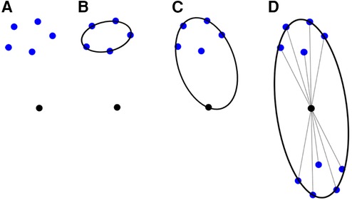
Figure 8. Different approaches to constructing a metric utilizing the minimum ellipsoid method.
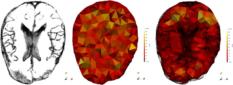
Figure 9. Registration points (left), isotropic mesh (center) and adaptive anisotropic sub-optimal mesh (right).
Table 8 presents data from two cases: (A: case 9 from Drakopoulos et al. (24), provided by HSH (male, with glioma at Left Frontal location of the brain, where Partial Resection is performed, with preop-MRI and iMRI image sizes and spacing: 448 × 512 × 176 and 0.488 × 0.488 × 1.00, respectively) and (B: case 18 from Drakopoulos et al. (24), provided by HSH (female, with glioma at Left Frontal location of the brain, where Total Resection is performed, with preop-MRI and iMRI image sizes and spacing: 448 × 512 × 176 and 0.488 × 0.488 × 1.00, respectively).
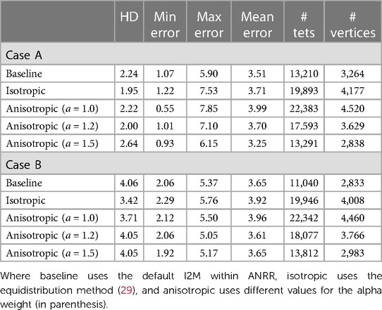
Table 8. Hausdorff distance (HD) and error using landmarks by experts reported in mm.
From Drakopoulos et al. (24) and for case A, the HD error for Rigid Registration (RR) and PBNRR (without optimal distribution of registration points) is 10.59 mm and 10.76 mm, respectively. For case B, the HD error for RR and PBNRR (without optimal distribution of registration points) is 25.72 mm and 23.90 mm, respectively. In both cases, the sub-optimal distribution within the ANRR method reduced the error to about five to six times compared to RR and PBNRR. While the error using specific landmarks improved (see Table 7; see max and mean error columns), the expert evaluation indicates that more work is needed. So, this problem remains open and it needs to be considered in the context of point and element outlier rejection schemes presented in this paper.
7. Future work
While attempting to solve the combinatorial problems listed in Section 6 with classical computing, we plan to evaluate the use of Quantum Computing as well. Edge (or Feature) Detection kernel is the simplest to implement on Quantum Processing Unites (QPUs) and along with the Block Matching (together require about 15% of total execution time) is our next goal. The FEM-solver which accounts for 60% of the total time could utilize (in the future) a well-known quantum algorithm for linear systems of equations (41). In the preliminary results.
The Quantum Hadamard Edge Detection (QHED) is a quantum image processing algorithm that shows great promise, as demonstrated by Yao et al. (40). However, the circuit depth of the image encoding section of the algorithm becomes exponential with respect to the number of qubits required for encoding, which is a major drawback. In the future, with advancements in quantum sensing, it may be possible to eliminate this step altogether. For now, Noisy Intermediate-Scale Quantum (NISQ)-era one can manage exponential memory requirements, for large medical images (such as pre-op and intraoperative brain images) by using an image decomposition and processing in parallel the individual sub-images to address current qubit4 fidelity (or decoherence) issues.
The image decomposition scheme proposed by Yao et al. (40) can cause false edges that appear across the output image. In addition, the use of decrement permutation in the original QHED proposal, shown in Figure 10, requires a very large number of multi-controlled NOT (MCX) gates, which results in an polynomial (42) number of controlled not (CX) gates for the mapping of the QHED circuit onto the quantum computer hardware. In short, both the image encoding, and the edge detection parts of the algorithm produce exponential circuit depth, which compounds a massive loss in fidelity.
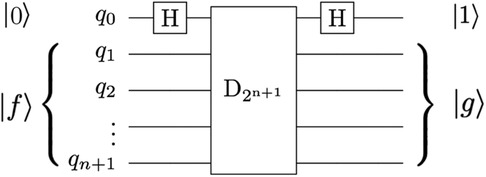
Figure 10. The QHED circuit proposed in Yao et al. (40) with an ancillary qubit. The D2n + 1 gate is a type of amplitude permutation that acts as a decrement operation on the input state vector.
To ensure correct boundary detection, we use classical space-filling curves commonly used in parallel numeric computations (43) to correct the artificial edges during the pre-and post-processing of input vectors. Figure 11 depicts our approach.
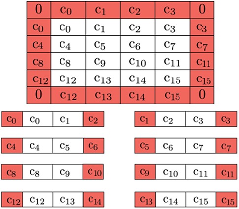
Figure 11. Buffer pixels of mirrored value are applied to the boundary of the overall image (0's for the corners, as they won’t be used). Further decomposition is possible by adding neighboring pixels to be used as a buffer due to QHED error. The red cells are ultimately disposed of in the final output.
We use a linear number of ancillary qubits to reduce the number of CX gates. We also address fidelity concerns with optimization techniques from Ferris et al. (44) to minimize hardware noise in both the amplitude encoding and QHED circuits.
Optimizing the topology and software of quantum circuits can improve results on physical hardware. A simulated noisy backend from IBM (45) is utilized to evaluate the results of the proposed QHED optimizations (see Figure 12). Based on our analysis of Figure 13, even with the optimizations we made to the original circuit, we still need a polynomial amount of CX operations with respect to an increasing number n of data encoding qubits. This results in a rapid loss of fidelity for any n > 5 number of data encoding qubits.
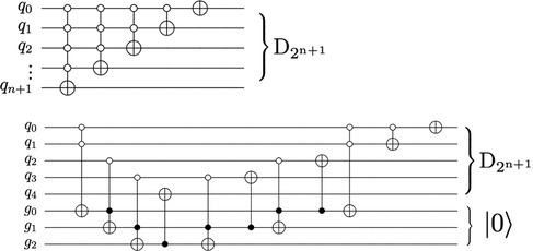
Figure 12. The circuit proposed in Yao et al. (40) for decrementing using n + 1 qubits require a descending series of MCX gates (top). An alternate decrement circuit (bottom) utilizes only CX and Toffoli gates, transpiling into a linear number of total CX gates.
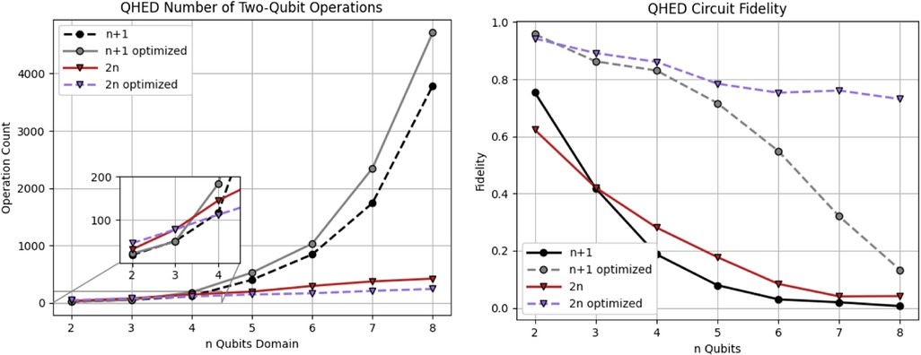
Figure 13. Analysis of the QHED algorithm using IBM's backend for both the proposed (red and blue) and Yao et al. (40) circuits (black and gray lines). Each of the two circuits is analyzed with and without full optimizations.
In summary, we have improved the Quantum Edge Detection method (40) to generate comprehensible results on NISQ-era hardware for our use case. We introduced new: (1) pre-and post-processing classical steps by introducing space-filling curves and buffer pixels to eliminate image artifacts and (2) decrement permutation circuit, optimizations for realistic images on today's QPUs, and additional optimization techniques to improve circuit fidelity and reduce the depth and the number of two-qubit operations.
8. Conclusion
We compared three outlier rejection schemes for deformable registration of brain images. The PBNRR scheme, developed by Clatz et al., reduces the mean average error of state-of-the-art RR from 5.6 mm to 4.3 mm. This scheme rejects, on average, 24% of registration points as potential outliers and takes about a minute to complete for the cases we analyzed. The NEMNRR scheme, developed by Liu et al., extends the PBNRR method by considering both point and element outliers and improves the error by an additional 0.6 mm (to 3.7 mm). This scheme removes 28% of registration points as potential outliers and takes six times longer to complete the registration for the same cases. The ANRR scheme developed by Drakopoulos et al. relies on geometric means and the PBNRR method. This combination improves the RR error by an additional 1.1 mm (i.e., from 5.6 mm to 3.2 mm). We selected nine cases from two retrospective studies over the last decade, using evaluations completed by two independent groups of experts, one using 25 cases (13) and the other using 5 additional (30 total) cases (24).
The HD error analysis suggests that the outlier rejection schemes improve the average RR error (near the tumor resected area) from 12 mm: (i) to 8 mm for PBNRR, (ii) to 5 mm for NEMNRR, and (iii) 3.6 mm, for ANRR5. Based on an evaluation using the average max error metric from two groups of independent experts, it was found that the registration accuracy at specific landmarks improved from 8.9 mm with RR to 6.8 mm with PBNRR, 7.7 mm with NEMNRR, and 6.5 mm with ANRR. It is important to note that the accuracy of MRI data is dependent on both the resolution of the images and the specific acquisition protocol utilized (22). Varying voxel resolutions can lead to varying accuracy.
Combining outlier rejection schemes significantly improves registration accuracy using the HD metric. A byproduct of this work and specifically the even sub-optimal solution of Problems I and II, along with earlier work on the robust HD metrics (37) has the potential to enable reliable and automatic measurement of registration accuracy, which is vital for the development of iterative outlier rejection schemes. Finally, emerging technologies like Deep Learning, Cloud, and Quantum computing could be used to determine patient-specific parameters and better distribute and on-the-fly compute new registration points to help reduce element outliers. Preliminary results appeared (24) and Section 6 are promising. However, for this work to have a clinical impact, more work is required to improve the accuracy of cases with deep brain tumors and further validate the current state of the software.
Author contributions
NC: Conceptualization, Funding acquisition, Methodology, Project administration, Resources, Supervision, Validation, Writing – original draft, Writing – review & editing, Formal Analysis, Investigation. AF: Conceptualization, Investigation, Methodology, Software, Validation, Visualization, Writing – review & editing, Writing – original draft. YL: Data curation, Methodology, Software, Validation, Visualization, Writing – review & editing, Formal Analysis, Conceptualization. AK: Software, Writing – review & editing. PF: Software, Visualization, Writing – review & editing. FD: Software, Visualization, Formal Analysis, Validation, Writing – review & editing. CT: Software, Visualization, Writing – review & editing. EB: Software, Visualization, Writing – review & editing. OC: Data curation, Formal Analysis, Methodology, Software, Validation, Writing – review & editing, Writing – original draft. NA: Conceptualization, Formal Analysis, Funding acquisition, Methodology, Resources, Supervision, Writing – review & editing. AG: Conceptualization, Funding acquisition, Investigation, Methodology, Resources, Writing – review & editing. PB: Supervision, Writing – review & editing. RK: Supervision, Visualization, Writing – review & editing, Conceptualization, Funding acquisition, Investigation, Methodology, Project administration, Resources.
Funding
The authors declare financial support was received for the research, authorship, and/or publication of this article.
AF, YL, PF, AK, FD, CT, and NC were partly supported by the NSF grants: CCS-0719929, CCS-0750901, CCF-0833081, CCF-1439079, NASA grant no. NNX15AU39A and Modeling and Simulation Fellowship at Old Dominion University. In addition, the Richard T. Cheng Endowment partially supports NC and EB. The John Simon Guggenheim Foundation supported NC. AF was supported in part by a grant from the Brain Science Foundation. RK, AG, and PB were supported in part by NIH grants: U41 RR019703, P01 CA67165, NIH R01NS049251, NIH 5R01EB027134, and NCIGT P41EB015898. This research was supported by an allocation through the TeraGrid Advanced Support Program. This work was performed [in part] using computational facilities at Old Dominion University and the College of William and Mary (in Virginia) enabled by grants from the National Science Foundation and Virginia's Commonwealth Technology Research Fund.
Acknowledgments
Table 7 is compiled after a labor-intensive evaluation performed by (i) Kyriaki Rafailia Kavazidi and Nikolaos Foroglou from the Department of Neurosurgery, Aristotle University of Thessaloniki, Greece, for the analysis in 30 cases appeared in (Drakopoulos et al., 2021) and (ii) Chengjun Yao, Jinsong Wu, Liangfu Zhou from the Department of Neurosurgery, Huashan Hospital, Shanghai, China, for 25 cases that first appeared in (Liu et al., 2014). The content is solely the authors' responsibility and does not necessarily represent the government agencies’ official views supporting.
Conflict of interest
The authors declare that the research was conducted in the absence of any commercial or financial relationships that could be construed as a potential conflict of interest.
The author(s) declared that they were an editorial board member of Frontiers, at the time of submission. This had no impact on the peer review process and the final decision.
Footnotes
1Rigid registration implemented in 3D Slicer v4.4.0.
2B-Spline non-rigid registration implemented in 3D Slicer.
3PBNRR implemented in ITKv4.7.0.
4Qubit, like the bit in classical computers, is the unit of storing and processing information in quantum computing.
5Analysis from five additional cases indicates a further improvement from an average 19 mm HD error to 3.6 mm (22).
Publisher's note
All claims expressed in this article are solely those of the authors and do not necessarily represent those of their affiliated organizations, or those of the publisher, the editors and the reviewers. Any product that may be evaluated in this article, or claim that may be made by its manufacturer, is not guaranteed or endorsed by the publisher.
References
1. National Brain Tumor Society. Facts & statistics. (2023). https://braintumor.org/brain-tumors/about-brain-tumors/brain-tumor-facts/
2. Grimson E, Kikinis R, Jolesz F, Black P. Image-guided surgery. Sci Am. (1999) 280(6):62–9. doi: 10.1038/scientificamerican0699-62
3. Orringer D, Golby A, Jolesz F. Neuronavigation in the surgical management of brain tumors: current and future trends. Expert Rev Med Devices. (2012) 9(5):491–500. doi: 10.1586/erd.12.429
4. Kikinis R, Pieper S, Vosburgh K. 3D Slicer: a platform for subject-specific image analysis, visualization, and clinical support. In: Jolesz F, editor. Intraoperative imaging and image-guided therapy. New York, NY: Springer (2014). p. 277–89. doi: 10.1007/978-1-4614-7657-3_19
5. Fedorov A, Beichel R, Kalpathy-Cramer J, Finet J, Fillion-Robin J-C, Pujol S, et al. 3D slicer as an image computing platform for the quantitative imaging network. Magn Reson Imaging. (2012) 30(9):1323–41, ISSN 0730-725X. doi: 10.1016/j.mri.2012.05.001
6. Golby A, editor. Image-guided neurosurgery, 1st ed. Cambridge, Massachusetts, USA: Academic Press (2015). p. 536.
7. Black P. Brains, minds, and the surgical planning laboratory. SPL 25th anniversary reception, brigham and women’s hospital, Boston. (2016).
8. Archip N, Clatz O, Whalen S, Kacher D, Fedorov A, Kot A, et al. Non-rigid alignment of preoperative MRI, fMRI, and DT-MRI with intra-operative MRI for enhanced visualization and navigation in image-guided neurosurgery. NeuroImage. (2007) 35:609–24. doi: 10.1016/j.neuroimage.2006.11.060
9. Clatz O, Delingette H, Talos I, Golby A, Kikinis R, Jolesz F, et al. Robust non-rigid registration to capture brain shift from intraoperative MRI. IEEE Trans Med Imaging. (2005) 24(11):1417–27. doi: 10.1109/TMI.2005.856734
10. Chrisochoides N, Fedorov A, Kot A, Archip N, Black P, Clatz O, et al. Toward real-time image guided neurosurgery using distributed and grid computing. SC 2006 conference, proceedings of the ACM/IEEE (2006). p. 37
11. Schenck J, Jolesz F, Roemer P, Cline H, Lorensen W, Kikinis R, et al. Superconducting open-configuration MR imaging system for image-guided therapy. Radiology. (1995) 195(3):805–14. doi: 10.1148/radiology.195.3.7754014
12. Advanced Multimodality Image Guided Operating Suite (AMIGO). (2023). Available at: https://www.brighamandwomens.org/research/amigo/advanced-multimodality-image-guided-operating-suite
13. Liu Y, Yao C, Drakopoulos F, Wu J, Zhou L, Chrisochoides N. A non-rigid registration method for correcting brain deformation induced by tumor resection. Med Phys. (2014) 41:101710. doi: 10.1118/1.4893754
14. Drakopoulos F, Liu Y, Foteinos P, Chrisochoides N. Towards a real-time multi-tissue adaptive physics-based non-rigid registration framework for brain tumor resection. Front Neuroinform. (2014) 8(11). doi: 10.3389/fninf.2014.00011
15. Sotiras A, Davatzikos C, Paragios N. Deformable medical image registration: a survey. IEEE Trans Med Imaging. (2013) 32 (7):1153–90. doi: 10.1109/TMI.2013.2265603
16. Frisken S, Luo M, Juvekar P, Bunevicius A, Machado I, Unadkat P, et al. A comparison of thin-plate spline deformation and finite element modeling to compensate for brain shift during tumor resection. Int J Comput Assist Radiol Surg. (2020) 15(1):75–85. doi: 10.1007/s11548-019-02057-2
17. Chrisochoides N, Fedorov A, Drakopoulos F, Kot A, Liu Y, Foteinos P, et al. To appear in handbook of dynamic data driven applications systems. Volume 3. Cham: Springer (2023).
18. Liu Y, Kot A, Drakopoulos F, Yao C, Fedorov A, Enquobahrie A, et al. An ITK implementation of a physics-based non-rigid registration method for brain deformation in image-guided neurosurgery. Front Neuroinform. (2014) 8(33). doi: 10.3389/fninf.2014.00033
19. Liu Y, Foteinos P, Chernikov A, Chrisochoides N. Multi-tissue mesh generation for brain images. In: International meshing roundtable, no. 19. (2010). p. 367.
20. Liu Y, Foteinos P, Chernikov A, Chrisochoides N. Mesh deformation-based multi-tissue mesh generation for brain images. Published in engineering with computers. Springer (2012). volume 8, no. 4. p. 305–18. doi: 10.1007/s00366-012-0265-y
21. Dempster AP, Laird NM, Rubin DB. Maximum likelihood from incomplete data via the EM algorithm. J R Stat Soc Ser B Methodol. (1977) 39(1):1–22. doi: 10.1111/j.2517-6161.1977.tb01600.x
22. NCIGT. Available at: https://central.xnat.org/app/template/XDATScreen_report_xnat_projectData.vm/search_element/xnat:projectData/search_field/xnat:projectData.ID/search_value/IGT_GLIOMA (Accessed August 2021).
23. Liu Y, Kot A, Drakopoulos F, Fedorov A, Enquobahrie A, Clatz O, et al. An ITK implementation of physics-based non-rigid registration method. Insight Journal (2012). doi: 10.54294/f9hilk
24. Drakopoulos F, Tsolakis C, Angelopoulos A, Liu Y, Yao C, Kavazidi K, et al. Adaptive physics-based non-rigid registration for immersive image-guided neuronavigation systems. Front Digit Health. (2021). 2. doi: 10.3389/fdgth.2020.613608
25. Wittek A, Miller K, Kikinis R, Warfield SK. Patient-specific model of brain deformation: application to medical image registration. J Biomech. (2007) 40(4):919–29. doi: 10.1016/j.jbiomech.2006.02.021
26. Drakopoulos F, Yao C, Liu Y, Chrisochoides N. An evaluation of adaptive biomechanical non-rigid registration for brain glioma resection using image-guided neurosurgery. Computational Biomechanics for Medicine. Springer (2017). p. 111–22. doi: 10.1111/j.2517-6161.1977.tb01600.x
27. Foteinos P, Chrisochoides N. High-quality real-time image-to-mesh conversion for finite element simulations. J Parallel Distrib Comput. (2014) 74(2):2123–40. doi: 10.1016/j.jpdc.2013.11.002
28. Foteinos P, Liu Y, Chernikov A, Chrisochoides N. An evaluation of tetrahedral mesh generation for non-rigid registration of brain MRI. In: Computational biomechanics for medicine v, 13th international conference on medical image computing and computer assisted intervention (miccai) workshop. Springer (2010). p. 126–37.
29. Fedorov A, Chrisochoides N. Tetrahedral mesh generation for non-rigid registration of brain mri: analysis of the requirements and evaluation of solutions. 17th international meshing roundtable (2008). p. 55–72
30. Garlapati R, Joldes G, Wittek A, Lam J, Weisenfeld N, Hans A, et al. Objective evaluation of the accuracy of intraoperative neuroimage registration. Computational biomechanics for medicine. Springer (2013). p. 87–99. https://www.semanticscholar.org/paper/Objective-Evaluation-of-Accuracy-of-Intra-Operative-Garlapati-Joldes/a700991c24de52beba3ff04e2fdafd763043339d
31. Canny J. A computational approach to edge detection. IEEE Trans Pattern Anal Mach Intell. (1986) (6):679–98.21869365
32. Commandeur F, Velut J, Acosta O. A VTK algorithm for the computation of the hausdorff D distance. VTK J. (2011). doi: 10.54294/ys4vxd
33. Molino N, Bridson R, Teran J, Fedkiw R. A crystalline, red-green strategy for meshing highly deformable objects with tetrahedra. International meshing roundtable (2003). p. 103–14
34. Fedorov A, Kikinis R, Warfield S, Chrisochoides N. Tetrahedral mesh generation for medical imaging. The insight journal, vol. For 2005 miccai open-source workshop. (2005). doi: 10.54294/yaqphu
35. Drakopoulos F, Ortiz R, Enquobahrie A, Sasaki-Adams D, Chrisochoides N. Tetrahedral image-to-mesh conversion software for anatomic modeling of arteriovenous malformations. In: Procedia engineering, 24th international meshing roundtable. (2015) 124:278–90.
36. Chernikov A, Chrisochoides N. Multi-Tissue tetrahedral image-to-mesh conversion with guaranteed quality and fidelity. SIAM Journal on Scientific Computing. (2011) 33(6):3491–508. doi: 10.1137/100815256
37. Fedorov A, Billet E, Prastawa M, Radmanesh A, Gerig G, Kikinis R, et al. Evaluation of brain MRI alignment with the robust hausdorff distance measures. In: Published in 4th international symposium on visual computing. Springer (2008). p. 594–603.
38. VTK. Available at: https://vtk.org (Accessed August 2023).
39. Dapogny C, Dobrzynski C, Frey P. Three-dimensional adaptive domain re-meshing, implicit domain meshing, and applications to free and moving boundary problems. J Comput Phys. (2014) 262:358–78. doi: 10.1016/j.jcp.2014.01.005
40. Yao X-W, Wang H, Liao Z, Chen M-C, Pan J, Li J, et al. Quantum image processing and its application to edge detection: theory and experiment. Physical Review X. (2017) 7(3). doi: 10.1103/physrevx.7.031041
41. Harrow AW, Hassidim A, Lloyd S. Quantum algorithm for linear systems of equations. Phys Rev Lett. (2009) 103(15). doi: 10.1103/PhysRevLett.103.150502
42. Vale R, Azevedo TMD, Araújo ICS, Araujo IF, da Silva AJ. Decomposition of Multi-controlled Special Unitary Single-Qubit Gates. arXiv [preprint]. (2023). doi: 10.48550/arXiv.2302.06377
43. Böhm C. Space-filling curves for high-performance data mining. arXiv [preprint]. (2020). doi: 10.48550/arXiv.2008.01684
44. Ferris KJ, Rasmusson AJ, Bronn NT, Lanes O. Quantum simulation on noisy superconducting quantum computers. arXiv [preprint]. (2022). doi: 10.48550/ARXIV.2209.02795
45. Abbas A, Andersson S, Asfaw A, Corcoles A, Bello L, Ben-Haim Y, et al. Learn quantum computation using qiskit. (2020). Available at: https://qiskit.org/textbook/
Appendix I
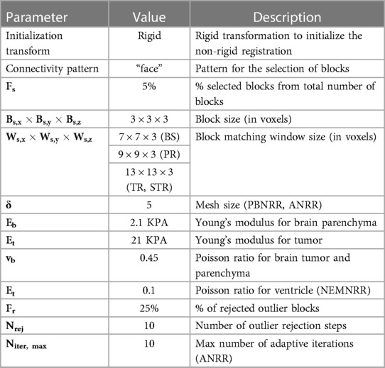
Table 9. A few important parameters are used for PBNRR, NEMNRR, and ANRR.
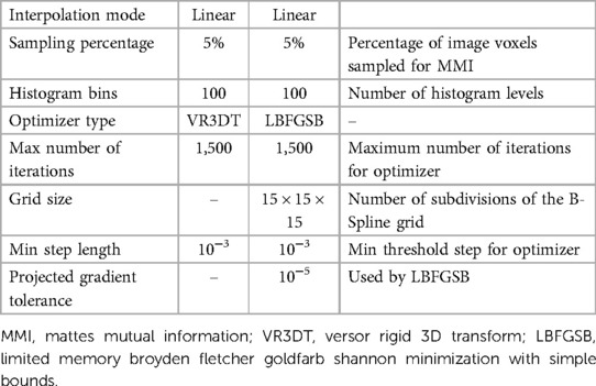
Table 10. Parameters used in this study for rigid registration (RR) and B-spline non-rigid registration methods implemented in 3D slicer.
Keywords: Image-guided neurosurgery, physics-based deformable registration, finite element methods (FEM), high performance computing, mesh generation
Citation: Chrisochoides N, Liu Y, Drakopoulos F, Kot A, Foteinos P, Tsolakis C, Billias E, Clatz O, Ayache N, Fedorov A, Golby A, Black P and Kikinis R (2023) Comparison of physics-based deformable registration methods for image-guided neurosurgery. Front. Digit. Health 5:1283726. doi: 10.3389/fdgth.2023.1283726
Received: 26 August 2023; Accepted: 2 November 2023;
Published: 8 December 2023.
Edited by:
Alkinoos Athanasiou, Aristotle University of Thessaloniki, GreeceReviewed by:
Kostas Nizamis, University of Twente, NetherlandsEleftheria Vellidou, Institute of Communication and Computer Systems (ICCS), Greece
© 2023 Chrisochoides, Liu, Drakopoulos, Kot, Foteinos, Tsolakis, Billias, Clatz, Ayache, Fedorov, Golby, Black and Kikinis. This is an open-access article distributed under the terms of the Creative Commons Attribution License (CC BY). The use, distribution or reproduction in other forums is permitted, provided the original author(s) and the copyright owner(s) are credited and that the original publication in this journal is cited, in accordance with accepted academic practice. No use, distribution or reproduction is permitted which does not comply with these terms.
*Correspondence: Nikos Chrisochoides bnBjaHJpc0BnbWFpbC5jb20=