 Tian-Hua Liu*
 Yu-Wei Wang
- Department of Electrical Engineering, National Taiwan University of Science and Technology, Taipei, Taiwan
Fault tolerant drive systems have played an increasing role for electric vehicles in order to improve reliability, availability, and to reduce maintenance. For safety reason, a fault-tolerant drive system, which includes some redundant devices and a traditional motor drive system, has been developed. This fault-tolerant system executes real-time fault detection, diagnosis, isolation, and control to make the fault-tolerant drive system operate normally even though some faults have happened. In this paper, an AC/DC converter faults, which includes a single-phase full-bridge rectifier diode fault, a three-phase full-bridge rectifier diode fault, and a DC-link capacitor fault are investigated. The fault-tolerant processes include fault detection, diagnosis, isolation, and control to improve the reliability of the drive system and reduce the disturbances during faulty interval. A digital signal processor, manufactured by Texas Instruments, type TMS320F2808, is used as a control center to achieve the fault tolerant processes. Experimental results validate theoretical analysis to demonstrate the correctness and feasibility of the proposed methods. The proposed method can be easily implemented in industrial products due to its simplicity.
Introduction
Several researchers have investigated the fault-tolerant PMSM drive systems. For example, Jlassi et al. proposed a robust control for a Hall sensor fault and an IGBT fault (Jlassi et al., 2017). Eickhoff et al. (2018) investigated a PWM switching algorithm to reduce torque pulsations when one power device is opened. An et al. (2015) studied the current residual vector to diagnose an open circuit of power switches and then executed fault-tolerant control to keep the motor rotating at the same speed. Zeng et al. used a three-leg four-switch inverter to drive a three-phase permanent magnet synchronous motor. The cost of the whole drive system was reduced; however, the torque ripple was increased (Zeng et al., 2017).
AC motors have replaced DC motors for more than 4 decades because the DC motor uses the brush and commutator, which requires maintenance and may cause arc when the brush touches the commutator. The AC motor includes induction motors and PMSMs. PMSMs have higher efficiency, high power density, and easier control characteristics than induction motors. As a result, most of electric vehicles and elevators use PMSMs as the drive systems. The details are discussed as follows. Figure 1 shows the fault-tolerant permanent-magnet synchronous motor fed by a single-phase full-bridge rectifier. To improve the reliability of the drive system, several fault-tolerant parts need to be investigated including one power switch of the inverter is opened or short-circuited (Liu et al., 1993; Liu et al., 2021). One phase of the motor is opened or partially short circuited (Akin et al., 2008). Some researchers proposed using different sensorless techniques to replace the encoder signal when it was faulty (Vas, 1993). In addition, the DC-link capacitor could be deteriorated after the PMSM drive system is operated 4–5 years. Furthermore, the rectifier diode also could be opened or short-circuited. To narrow down the research topic, in this paper, the fault-tolerant cases of the DC-link capacitor fail and the rectifying diode fail are investigated. Figure 1 shows the proposed fault-tolerant surface-mounted PMSM drive system with a single-phase full-bridge rectifier. The single-phase full-bridge rectifier includes four diodes, D1, D1, D2, and D2. Because the diodes are quite cheap, in this paper, when any diode is opened or short-circuited, the DSP uses a back-up full-bridge rectifier to replace the faulty full-bridge rectifier via a single-pole double-throw mechanical switch. The high speed fuses, the Fa and Fb are used to transfer the diode from a short circuited into an open circuited. The resistances, R1 and R2, are used to limit the surge current when the capacitors C1 and C1 are immediately connected into the DC-link. The DC switches S4 and S5 are used to short circuit the resistor and then reduce the power consumption. In this paper, the resistances R1 and R2 are both 50
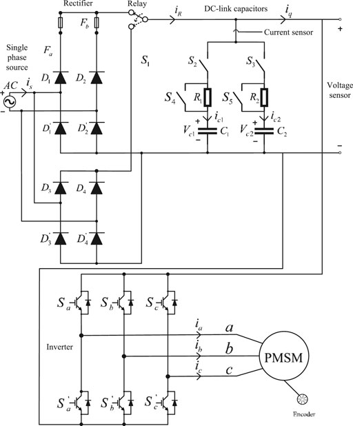
FIGURE 1. A fault-tolerant SPMSM drive system with a single-phase full-bridge rectifier.
Figure 1 includes an AC source, AC/DC converters, DC-link capacitors, an inverter, and a surface-mount PMSM (SPMSM). In the real world, each part of the SPMSM drive system could be faulty. To improve the reliability of the whole system, a fault-tolerant configuration of the SPMSM drive system is required. Several researchers have investigated this issue. For example, Chai et al. studied the fault-tolerant control method when the SPMSM is faulty (Chai et al., 2019). Liu et al. used periodic control algorithms to improve the dynamic responses when the inverter has one IGBT open circuited or short circuited (Liu et al., 2019). In addition, Liu et al. also proposed a predictive controller and a sliding-mode estimator to improve the reliability of the SPMSM drive system when one Hall-effect sensor or the encoder is faulty (Liu and Chang, 2019). Several researchers focused on a novel fault-tolerant inverter (Li et al., 2017), stator turn fault tolerant method (Hadef et al., 2010), and Hall sensor fault tolerant method (Mehta et al., 2015). For AC/DC converter fault tolerant method, Lee et al. proposed a DC-link capacitor estimation when the motor was stopped (Lee et al., 2008).
In this paper, the authors focus on the fault-tolerant control of the AC/DC converter. The faulty cases include: one diode opened, one diode short-circuited, and a degradation of the DC-link capacitor. The fault-tolerant control of AC/DC converter for an SPMSM drive system has not been investigated by previous papers (Jlassi et al., 2017; Eickhoff et al., 2018; An et al., 2015; Zeng et al., 2017; Liu and Chang, 2019; Liu et al., 2021; Akin et al., 2008; Vas, 1993; Chai et al., 2019; Liu et al., 1993; Liu and Chang, 2019; Li et al., 2017; Hadef et al., 2010; Mehta et al., 2015). The paper first time proposes to measure the input AC side currents to diagnosis the open circuit or short-circuited for a full-bridge rectifier, and then to execute its fault-tolerant control. In addition, the paper first time proposed the estimation the DC-link capacitor when the motor is operated at different speeds. In previously published paper, the DC-link capacitor was estimated when the motor was stopped (Lee et al., 2008). Although the proposed methods are straight forward, they are original ideas and have not been investigated in the previous papers. In addition, the proposed methods are practical and useful. The details are as follows.
Fault Tolerant Control of Different Full-Bridge Rectifier Converters
(a) Single-phase Full-bridge Rectifier AC/DC Converter
In Figure 1, if diode
where
For a normal full-bridge operation, the ripple frequency of the output DC voltage is 120 Hz, which has a time interval of 8.33 m s, and an average of the output voltage is
When one diode is opened, the single-phase full-bridge rectifier becomes a half-bridge rectifier, which produces an output average voltage as
In addition, the frequency of the output ripple reduces to 60 Hz, which has a time interval of 16.66 m s.
In the real world, the output voltage is seriously affected by the DC-link capacitance, which is used as a low-pass filter. In addition, the output voltage is also related to the load. As a result, it is not feasible to use the output voltage to detect whether the single-phase full-bridge rectifier has a diode opened or not. To solve the problem, in this paper, the output capacitor current is used to detect whether the single-phase full-bridge rectifier has a diode opened or not. From Figures 2A,B, one can observe that the diode currents appear every 8.33 m s in the ac input side. However, the diode currents appear every 16.6 m s when one diode of the full-bridge rectier is faulty. As a result, we can observe that the frequency of the charging current of the capacitor reduces to 50% as one diode is opened, in which the frequency of the output voltage ripples become half. The DSP uses this characteristic to identify when the single-phase full-bridge rectifier is faulty. After that, the DSP controls the relay to disconnect the DC-link output from the faulty rectifier, and then the relay connects the DC-link output to the back-up single-phase full-bridge rectifier.
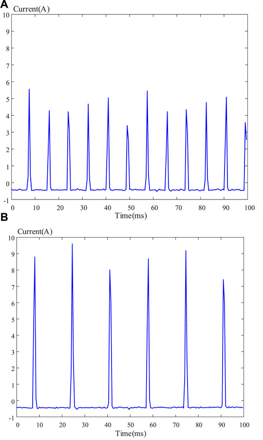
FIGURE 2. The current of the capacitor of a single-phase full-bridge rectifier. (A) Normal operation, (B) one diode opened.
Figure 3 shows the variations of the DC-link output voltages. From Figure 3, the DC-link voltage is varied from 150 to 154 V when the single-phase full-bridge rectifier is used. The DC-link voltage is varied from 142 to 154 V after one diode is opened. By measuring the voltage drops of the DC-link capacitor but not the variations of the frequency of the DC-link capacitor, the faulty of the DC-link capacitor is diagnosed (Isermann, 2006). However, the DC-link voltage is also seriously affected by the external load of the surface-mounted PMSM. As a result, a wrong diagnosis could be generated when a heavy external load is added. To avoid this situation, the capacitance current is used to replace the capacitance voltage to determine if one diode of the single-phase full-bridge rectifier is opened.
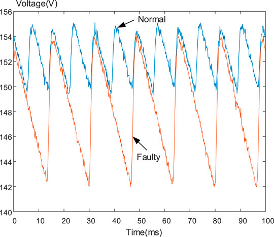
FIGURE 3. The DC-link capacitor voltage at normal operation and faulty condition.
Electrolytic capacitors can be degraded because when they are operated at overvoltage, reverse-voltage, high temperature, or lack of electrolyte. In these situations, the equivalent series resistance (ESR) is increased and the capacitance is decreased (Isermann, 2006). To obtain good performance, the motor drive systems require suitable dc-link capacitors to filter the voltage variations (Wang and Blaabjerg, 2014)-(Grotzbach and Draxler, 1989). To diagnose the fault of a capacitor, a Kalman filter for state estimation has been proposed by Ginart et al. (Farhadi et al., 2018). However, the computations of this method are very complicated. To simplify this issue, in this paper, a new method is proposed by real-time measurement of the voltage and current for the capacitor. The details are as follows.
The relationship between a capacitor current,
In fact, a digital signal processor (DSP) is used in this paper. The discrete-form relationship, therefore, can be developed as follows:
where k is the sampling times,
The capacitor voltage variations are detected by using a voltage sensor across the DC-link capacitor. The sampling frequency of the capacitor current and voltage is 10 kHz. When the estimated capacitor
(b) Three-Phase Full-bridge Rectifier AC/DC Converter
Many industrial applications, such as elevators and subway trains need high power to generate high torque for their loads. These applications cannot be achieved by using only a single-phase full-bridge rectifier (Cardoso, 2019; Ginart, 2018; Lu and Sharma, 2008; Errabelli and Mutschler, 2012). Therefore, three-phase full-bridge rectifiers are widely used in high-power applications. In addition, the percentage of the output DC-link voltage ripple is reduced because the frequency of the output voltage ripple is 360 Hz but not 120 Hz. Figure 4 shows the configuration of a fault-tolerant three-phase AC/DC converter, which includes a three-phase voltage source, a normal three-phase AC/DC full-bridge rectifier, a back-up three-phase AC/DC full-bridge rectifier, a single pole double throw switch, two resistors to limit the transient current, two DC-link capacitors, and two parallel switches. During the normal operation, the normal three-phase AC/DC full-bridge rectifier is used, the relay is connected the DC-link bus to the normal full-bridge rectifier, and the S2 switch, S4 switch, R1 resistor, and C1 capacitor are used. The other parts are belong to the back-up components, including the back-up full-bridge rectifier, S3 switch, S5 switch, R2 resistance, and C2 capacitor. In addition, the relay is connected the back-up full-bridge rectifier to the DC-bus. The details are discussed as follows.
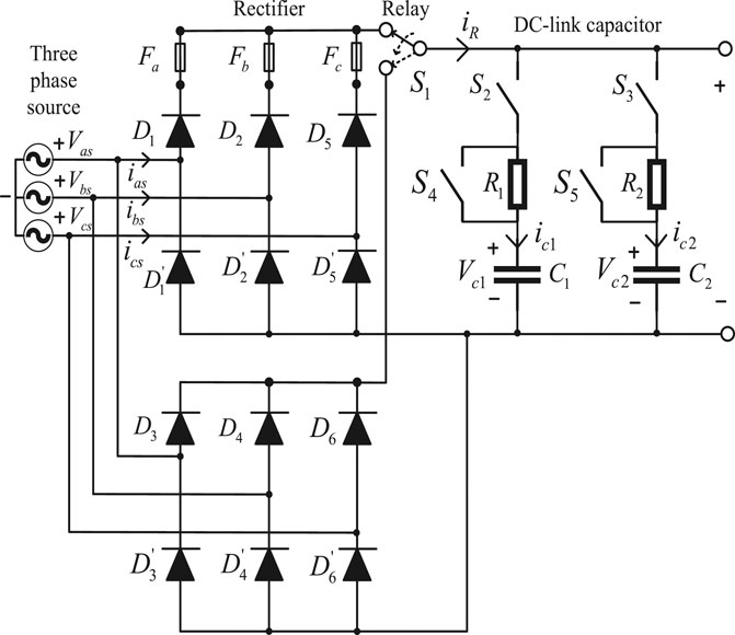
FIGURE 4. Configuration of a fault-tolerant three-phase AC/DC converter.
Generally speaking, by using the three-phase full-bridge rectifier, the voltage ripple in the DC-link capacitor is 360 Hz. As a result, each period of the voltage ripple is 2.77 m s. In every period, the capacitor current increases and then decreases. In addition, the current waveform is discontinuous. The detailed current waveform is shown in Figure 5A, which has similar amplitudes and the same time interval.
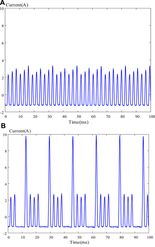
FIGURE 5. The current waveforms of the DC-link capacitor. (A) normal operation, (B) one diode opened.
When one diode is opened, the input current is obviously distorted as shown in Figure 5B. The opened diode produces zero current. Then, the next turn on diodes generate a huge current, which is more than twice of the normal current. It is not difficult for a DSP to detect the one-diode open fault, and then to control the relay. The relay connects the DC-link capacitor to the back-up three-phase full-bridge rectifier, and disconnects the DC-link capacitor to the normal three-phase full-bridge rectifier. Figure 6 shows the voltages of the capacitor at the normal operation and faulty condition. As one can observe, the voltage ripple increases when one diode is opened. In this paper, the DSP uses the capacitor current to detect the faulty condition instead of using the capacitor voltage. The major reason is that the DC-link voltage could be obviously affected by the external load of the motor, which may cause wrong diagnosis.
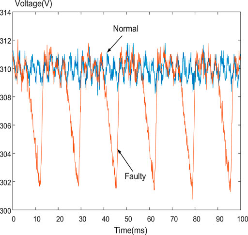
FIGURE 6. The DC-link voltage at normal condition and one-diode opened condition.
Electrolytic capacitors suffer from low reliability because their liquid are being evaporated. The health of electrolytic capacitors is affected by the operating conditions, which include working temperatures, voltages, currents, and frequencies. Degradation of capacitors cause the increasing of the capacitors’ equivalent resistances and the decreasing of the capacitors’ equivalent capacitances. In addition, continued degradation of the capacitor leads to the DC-link output voltage to drop below its specified output value. It is possible to construct the mathematical model of a capacitor, and then to use state forecasting to determine whether a capacitor is faulty or not. However, it is too complicated. To simplify this issue, in this paper, the real-time estimation of the capacitor value is used by measuring the voltage and current of the capacitor. The computation of the proposed method is very simple. As a result, it is easy to implement by using a DSP.
The capacitor voltage, which is measured by a DSP, is expressed as follows
where k is the sampling times,
In this paper, the sampling time is selected as 10 kHz. When the estimated capacitor
Implementation
The block diagram of the implemented fault-tolerant surface-mounted PMSM drive is shown in Figure 7A. The block diagram was discussed in references (Liu et al., 1993; Liu et al., 2021; Liu et al., 2019; Liu and Chang, 2019) by one of the authors in this paper. This author investigated the faulty of one power switch, which includes one power switch is opened or short-circuited, of the inverter in references (Liu et al., 1993; Liu et al., 2021; Liu et al., 2019; Liu and Chang, 2019). Then, a new switching patterns of the inverter were proposed to maintain the motor’s speed and torque as a constant. In this paper, the authors assume the inverter is normally operated and the single–phase AC/DC rectifier or the three-phase AC/DC rectifier is faulty, including one diode is opened, or short-circuited or the DC-link capacitor is faulty. First, the speed command
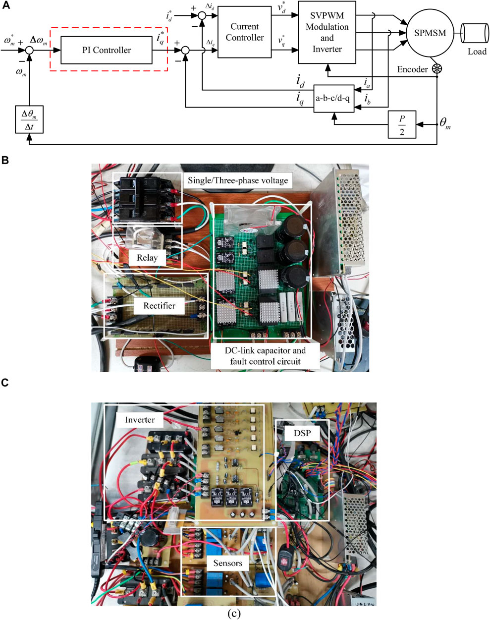
FIGURE 7. Fault-tolerant surface-mounted PMSM drive system. (A) block diagram, (B) AC/D converter, and (C) inverter and DSP.
Experimental Results
Several experimental results are shown here to validate the theoretical analysis. Figure 8 shows the photograph of the SPMSM drive system and its dynamometer. Table 1 shows the specification of the SPMSM that used in this paper.
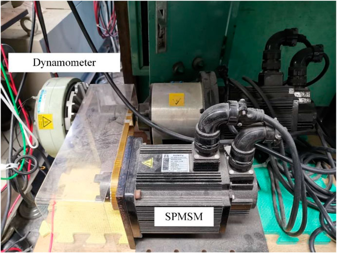
FIGURE 8. Photograph of the surface-mounted PMSM drive system.
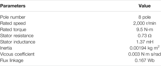
TABLE 1. Specification of surface-mounted PMSM.
Figures 9A,B show the waveforms when using the fault-tolerant algorithms of a diode opened for a single-phase full-bridge rectifier. Figure 9A demonstrates the DC-link voltage. When a diode opened, the voltage ripples increase to
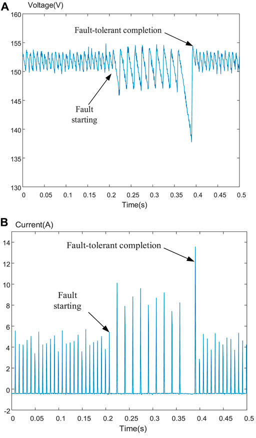
FIGURE 9. One diode opened for a single-phase full-bridge rectifier. (A) DC-link voltage, (B) capacitor current.
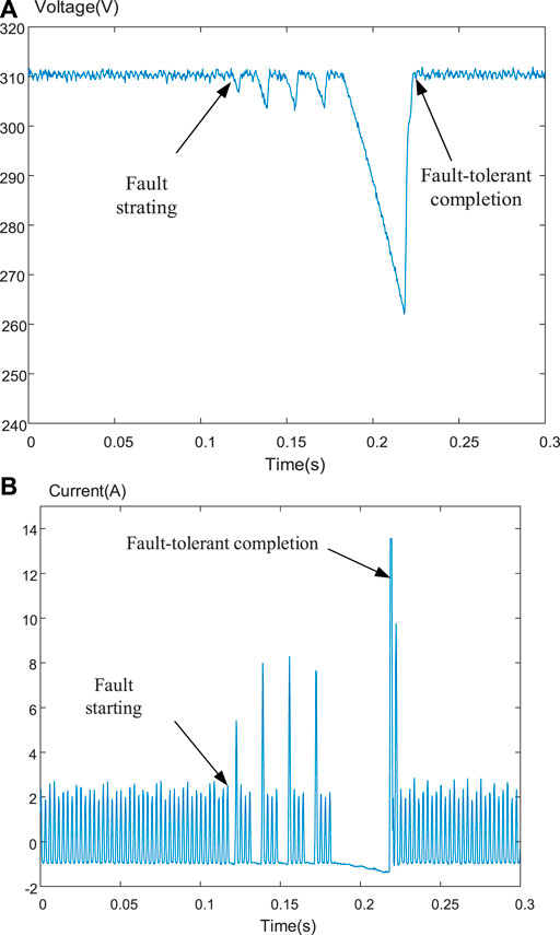
FIGURE 10. One diode opened for a three-phase full-bridge rectifier. (A) DC-link voltage, (B) capacitor current.
Figures 11A,B show the measured waveforms of the DC-link capacitor fault for a single-phase full-bridge rectifier. Figure 11A demonstrates the measured DC-link voltage, and Figure 11B demonstrates the estimated capacitor. When the DSP detects the capacitor becomes 720 µF, the fault-tolerant algorithms are executed to connect another back-up capacitor, which is 720 µF. The total value of the capacitor returns to the original value. Figures 12A,B show the measured waveforms of the DC-link capacitor fault for a three-phase full-bridge rectifier. Figure 12A demonstrates the DC-voltage, which provides a DC average voltage near 308.5 V. Figure 12B demonstrates the estimated capacitor, which is 1,440 µF in normal. When the DC-link capacitor is faulty, the capacitance value reduces to 720 µF; however, it returns to its original capacitance 1,440 µF after the fault tolerant algorithms are executed.
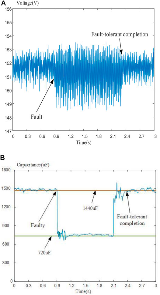
FIGURE 11. The DC-link capacitor fault for a single-phase full-bridge rectifier. (A) DC-link voltage, (B) estimated capacitor.
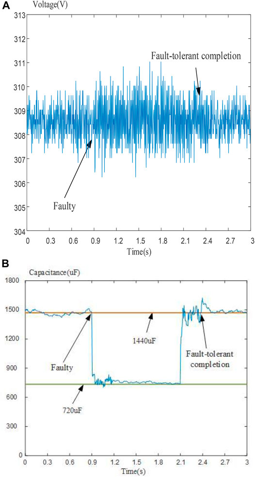
FIGURE 12. The DC-link capacitor fault for a three-phase full-bridge rectifier. (A) DC-link voltage, (B) estimated capacitor.
Figures 13A,B show the measured waveforms at 300 r/min and 2 N m by using a single-phase full-bridge rectifier. Figure 13A demonstrates the a-phase measured current, which is near a sinusoidal waveform. Figure 13B shows the line-line voltage at the same case. Figure 13C shows the DC-link current at the same case. Figure 13D shows the input ac current by using a single-phase full-bridge rectifier, which is obviously a discontinuous current. Figure 13E shows the input ac current by using a three-phase full-bridge rectifier, as you can observe, the frequency of the current pulsations become triple when it is compared to a single-phase full-bridge rectifier.
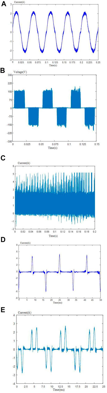
FIGURE 13. Measured waveforms of the surface-mounted PMSM at 300 r/min and 2 N m. (A) Current, (B) line voltage, (C) DC-link current, (D) 1-phase input current, and (E) 3-phase input cutrrent.
Comparing with the previously proposed method (Isermann, 2006), which only needed one voltage sensor, the proposed method in our paper requires one voltage sensor and one current sensor to measure the voltage and current of the DC-link capacitor. However, the proposed method in our paper provides a better accurate of the diagnosis results than the previously published paper (Isermann, 2006). In addition, comparing with reference (Lee et al., 2008), which estimated the DC-link capacitor when the motor was stopped, our paper can compute the DC-link capacitor when rotor is operated at different speeds.
Conclusion
In this paper, one diode opened for a single-phase full-bridge rectifier and a three-phase full-bridge rectifier, and a DC-link capacitor degraded fault for a single-phase full-bridge rectifier and a three-phase full-bridge rectifier are investigated. Experimental results verify the proposed method which uses real-time detection and diagnosis of the faults and then executing the fault-tolerant control algorithms. The surface-mounted PMSM drive system can be operated normally after the fault-tolerant control is executed. The proposed method can be used in industry to improve the reliability of the motor drive system due to its simplicity.
Data Availability Statement
The raw data supporting the conclusions of this article will be made available by the authors, without undue reservation.
Author Contributions
T-HL research topic, English paper writing, methods. Y-WW Experimental results, Simulation results, Drawing figures.
Conflict of Interest
The authors declare that the research was conducted in the absence of any commercial or financial relationships that could be construed as a potential conflict of interest.
Acknowledgments
The paper is supported by Ministry of Science and Technology, under Grant MOST 108-2221-E-011-085.
References
Akin, B., Orguner, U., Toliyat, H. A., and Rayner, M. (2008). Phase-Sensitive Detection of Motor Fault Signatures in the Presence of Noise. IEEE Trans. Ind. Electron. 55 (6), 2539–2550. doi:10.1109/tie.2008.921681
An, Q.-T., Sun, L., and Sun, L.-Z. (2015). Current Residual Vector-Based Open-Switch Fault Diagnosis of Inverters in PMSM Drive Systems. IEEE Trans. Power Electron. 30 (5), 2814–2827. doi:10.1109/tpel.2014.2360834
Cardoso, A. J. M. (2019). Diagnosis and Fault Tolerance of Electrical Machines, Power Electronics and Drives. England & Wales: The Institution of Engineering and Technology.
Chai, F., Gao, L., Yu, Y., and Liu, Y. (2019). Fault-tolerant Control of Modular Permanent Magnet Synchronous Motor under Open-Circuit Faults. IEEE Access 7, 154008–154017. doi:10.1109/access.2019.2948363
Eickhoff, H. T., Seebacher, R., Muetze, A., and Strangas, E. G. (2018). Post-fault Operation Strategy for Single Switch Open-Circuit Faults in Electric Drives. IEEE Trans. Ind. Appl. 54 (3), 2381–2391. doi:10.1109/tia.2018.2807404
Errabelli, R. R., and Mutschler, P. (2012). Fault-Tolerant Voltage Source Inverter for Permanent Magnet Drives. IEEE Trans. Power Electron. 27 (2), 500–508. doi:10.1109/tpel.2011.2135866
Farhadi, M., Fard, M. T., Abapour, M., and Hagh, M. T. (2018). DC-AC Converter-Fed Induction Motor Drive with Fault-Tolerant Capability under Open- and Short-Circuit Switch Failures. IEEE Trans. Power Electron. 33 (2), 1609–1621. doi:10.1109/tpel.2017.2683534
Ginart, A. (2018). Fault Diagnosis for Robust Inverter Power Drives. England & Wales: The Institution of Engineering and Technology.
Grotzbach, M., and Draxler, B. (1989). Line Side Behavior of Uncontrolled Rectifier Bridges with Capacitor DC Smoothing. Aachen, German: IEEE EPE, 761–764.
Hadef, M., Mekideche, M. R., and Djerdir, A. (2010). Vector Controlled Permanent Magnet Synchronous Motor Drive with Stator Turn Fault. Rome: IEEE ICEM. doi:10.1109/icelmach.2010.5608104
Isermann, R. (2006). Fault-Diagnosis Systems-An Introduction from Detection to Fault Tolerance. Berlin: Springer.
Jlassi, I., Estima, J. O., El Khil, S. K., Bellaaj, N. M., and Cardoso, A. J. M. (2017). A Robust Observer-Based Method for IGBTs and Current Sensors Fault Diagnosis in Voltage-Source Inverters of PMSM Drives. IEEE Trans. Ind. Appl. 53 (3), 2894–2905. doi:10.1109/tia.2016.2616398
Lee, K., Kim, M., Yoon, J., Lee, S., and Yoo, J. (2008). Condition Monitoring of DC-link Electrolytic Capacitors in Adjustable-Speed Drives. IEEE Trans. Ind. Appl. 44 (5), 1606–1613. doi:10.1109/tia.2008.2002277
Li, H., Li, W., and Ren, H. (2017). Fault-tolerant Inverter for High-Speed Low-Inductance BLDC Drives in Aerospace Applications. IEEE Trans. Power Electron. 32 (3), 2452–2463. doi:10.1109/tpel.2016.2569611
Liu, T. H., and Chang, S. F. (2019). Fault‐tolerant Matrix‐converter‐controlled IPMSM‐drive System Using a Predictive Controller and Sliding‐mode Estimator. J. Eng. 2019 (11), 8225–8235. doi:10.1049/joe.2019.0084
Liu, T. H., Fu, J. R., and Lipo, T. A. (1993). A Strategy for Improving Reliability of Field-Oriented Controlled Induction Motor Drives. IEEE Trans. Ind. Appl. 29 (5), 910–918. doi:10.1109/IAS.1991.178194
Liu, T. H., Mubarok, M. S., Hendriyono, D., and Suwarno, J. (2021). Speed‐loop Frequency‐adaptive and Current‐loop Optimal Harmonic Periodic Controllers for Fault‐tolerant SPMSM Drive Systems. IET Electric Power Appl. 15, 629–642. doi:10.1049/elp2.12053
Liu, T. H., Mubarok, M. S., Ridwan, M., and Suwarno, J. (2019). Design and Implementation of a Speed-Loop-Periodic-Controller-Based Fault-Tolerant SPMSM Drive System. Energies 12 (9), 1–31. doi:10.3390/en12193593
Lu, B., and Sharma, S. K. (2008). A Survey of IGBT Fault Diagnostic Methods for Three-phase Power Inverter. Beijing, China: IEEE ICCMD, 756–763.
Mehta, H., Thakar, U., Joshi, V., Rathod, K., and Kurulkar, P. (2015). Hall Sensor Fault Detection and Fault Tolerant Control of PMSM Drive System. Pune, India: IEEE ICIC. doi:10.1109/iic.2015.7150817
Vas, P. (1993). Parameter Estimation, Condition Monitoring, and Diagnosis of Electrical Machines. ” Oxford, UK: Calarendon Press.
Wang, H., and Blaabjerg, F. (2014). Reliability of Capacitors for DC-link Applications in Power Electronic Converters-An Overview. IEEE Trans. Ind. Appl. 50 (5), 3569–3578. doi:10.1109/tia.2014.2308357
Keywords: fault-tolerance, AC/DC converter, permanent magnet synchronous motor, digital signal processor, drive system
Citation: Liu T-H and Wang Y-W (2021) Implementation of a Fault-Tolerant AC/DC Converter for Permanent Magnet Synchronous Motor Drive Systems. Front. Electron. 2:670077. doi: 10.3389/felec.2021.670077
Received: 20 February 2021; Accepted: 22 April 2021;
Published: 01 July 2021.
Edited by:
Rui Zhang, University of New South Wales, AustraliaReviewed by:
Ton Duc Do, Nazarbayev University, KazakhstanWenzheng Xu, Beijing Jiaotong University, China
Copyright © 2021 Liu and Wang. This is an open-access article distributed under the terms of the Creative Commons Attribution License (CC BY). The use, distribution or reproduction in other forums is permitted, provided the original author(s) and the copyright owner(s) are credited and that the original publication in this journal is cited, in accordance with accepted academic practice. No use, distribution or reproduction is permitted which does not comply with these terms.
*Correspondence: Tian-Hua Liu, TGl1QG50dXN0LmVkdS50dw==