 Yonglu Liu
 Yiqi Zuo
 Liang Yuan
- 1School of Automation, Central South University, Changsha, China
- 2Hunan Provincial Key Laboratory of Power Electronics Equipment and Gird, Central South University, Changsha, China
Aiming to handle the inherent double-line frequency ripple power in single-phase power systems, a lot of active power decoupling (APD) topologies have been developed. In this paper, a general method is introduced to synthesize APD topologies. The main construction idea is to insert a rectifier/inverter into asymmetrical H-bridge circuits (AHCs) or replace the switch/diode in the AHCs with a rectifier/inverter. This approach not only reveals the formation process of existing APD topologies but also deduces new APD topologies. Finally, an experimental case study has been carried out to illustrate the feasibility and effectiveness of the proposed topology synthesis method.
1 Introduction
The double-line frequency ripple power inherently exists in the single-phase system, which results in low-frequency ripple on the dc-link voltage/current. The undesirable ripple degrades system performances, such as reducing the lifetime and efficiency of fuel cells (Fontes et al., 2007), accelerating battery aging (Kim and Shin, 2012), and leading to a light flicker of the light-emitting diode (LED) (Li et al., 2016).
To limit the double-line frequency ripple, a bulk electrolytic dc-link capacitor is commonly adopted, but this leads to large volume, low power density, and poor lifetime. Active power decoupling (APD) technology (Hu et al., 2013; Sun et al., 2016) is developed to address this issue. The technology requires the construction of the APD topology, which generally needs an auxiliary decoupling circuit. The decoupling circuit consists of relatively small sizes as well as long lifetime energy storage components and extra active switches. Through diverting the double-line frequency ripple power to the decoupling circuit, the APD technology has proven to be an effective solution to buffer the double-line frequency ripple power while possessing high power density and even high reliability. The APD topologies directly affect the features of the system, such as efficiency, cost, and operation limits. Hence, the research on APD topology configurations has become a hot research topic in power electronics. Several decoupling circuits are proposed in succession for power factor correction (PFC) rectifiers (Ohnuma and Itoh, 2014; Li et al., 2017; Qi et al., 2019a; Qi et al., 2019b), current source type converters (Han et al., 2015; Ohnuma et al., 2015; Liu et al., 2016; Liu et al., 2017; Zare et al., 2017; Liu et al., 2019; Xiong et al., 2020; Wang et al., 2021), and voltage source type inverters (Mishra et al., 2012; Ravindranath et al., 2013; Nguyen et al., 2015a; Nguyen et al., 2015b; Davise and Prince, 2017; Gautam and Fulwani, 2019; Nguyen et al., 2019).
For PFC rectifiers, the circuit proposed in Ohnuma and Itoh (2014) achieved APD and PFC by adding a diode, a switch, and a decoupling capacitor. The filter inductor in the conventional PFC rectifier is connected in series with the grid along with the rectified waveform current, while in Ohnuma and Itoh (2014),the filter inductor is connected in series with the load along with a constant current. However, the decoupling capacitor voltage is higher than the peak grid voltage to reversely bias the rectifier diodes. In addition, its output voltage must be less than half of the peak grid voltage. Qi et al. (2019b) employed three-level to eliminate decoupling capacitor voltage limitations. The buck–boost rectifier is used in Li et al. (2017) to break the output voltage limitation by rotating the basic three-terminal cell used in Ohnuma and Itoh (2014). However, the filter inductor current in the study by Li et al. (2017) is equal to the sum of the load current and the rectified grid current, and the decoupling capacitor voltage is more than the sum of the grid and load voltages. Then, Qi et al. (2019a) proposed a modified topology that only adding a diode. It reduces the voltage stress by limiting the decoupling capacitor voltage to less than the sum of the grid and load voltages.
For the current source type converters, a topology is proposed in Han et al. (2015) by inserting an asymmetrical H-bridge circuit (AHC) into the dc-link bus to buffer the ripple power. The AHC works independently with the original current source rectifier (CSR) and is extended for PV applications (Zare et al., 2017). However, two additional active switches are added in Han et al. (2015) and Zare et al. (2017). In order to minimize the switch count, a switch-multiplexing topology combining the AHC and rectifier bridge is proposed in Liu et al. (2016), as shown in Figure 1. It has two decoupling capacitors, and the two capacitors work between partitions, which tightens the constraint of the decoupling capacitor voltage. Moreover, it is interesting that the current source type APD topology can be merged with other functions (Liu et al., 2017; Liu et al., 2019; Xiong et al., 2020). In Liu et al. (2017), the boost is achieved to extend the output voltage range by reconstructing the decoupling circuit in Han et al. (2015), as shown in Figure 2. Liu et al. (2019) reported the inversion version of the rectifier in Liu et al. (2017). In the study by Xiong et al. (2020), the open-circuit threat of the dc link inductor current is eliminated with the help of the decoupling circuit.
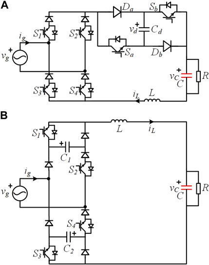
FIGURE 1. Switch multiplexing: (A) AHC independent of the rectifier bridge [adapted from Han et al. (2015), with permission from John Wiley and Sons]; (B) AHC combined with the rectifier bridge [adapted from Liu et al. (2016), with permission from IEEE].
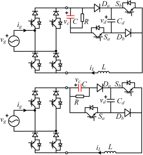
FIGURE 2. Boost APD [adapted from Liu et al. (2017), with permission from IEEE)].
For the voltage source type inverters, an inverted form based on the study by Ohnuma and Itoh (2014) of the PFC rectifier is proposed in Ohnuma et al. (2015). However, it only operates on the unit power factor. To overcome this drawback, one approach involves connecting a diode in series before each switch (Wang et al., 2021), and an alternative approach involves the substitution of the grid LC filter with an L filter. The latter is changed into a special voltage source inverter (VSI), which is called the single-phase quasi-switched-boost inverter (qSBI) or current-fed switched inverter (CFSI) (Nguyen et al., 2015a; Gautam and Fulwani, 2019; Nguyen et al., 2019). These inverters, without requiring extra hardware, possess the features of the Z-source inverter (ZSI) and avoiding shoot-through problems. The double-line frequency ripple power can be buffered in the intermediate capacitor by designing a suitable controller. Another similar inverter is the developed switched-boost inverter (SBI) (Mishra et al., 2012; Ravindranath et al., 2013). A comparison between ZSI, SBI, and CFSI has been carried out in Ohnuma and Itoh (2014), Nguyen et al. (2015b), and Davise and Prince (2017).
Although various APD topologies have been proposed for rectification and inversion applications, their appearance are random and dependent on the inspiration of the researchers. The relationship between the aforementioned decoupling circuits lacks revelation, which is not conducive to derive new APD topologies. In this paper, a general method is introduced to synthesize APD topologies by inserting a rectifier/inverter into asymmetrical H-bridge circuits (AHCs) or replacing the switch/diode in the AHCs with a rectifier/inverter. This construction idea not only reveals the formation process of the aforementioned topologies and many others but also deduces new APD topologies.
The remainder of this paper is organized as follows: Section 2 introduces three basic types of AHCs. Section 3 introduces the basic APD topology synthesis methods. In Section 4, the extension of the proposed methods is given. The experimental results are carried out in Section 5. Finally, Section 6 concludes the paper.
2 Asymmetrical H-bridge circuits
Figure 3 shows the circuit structures of the AHCs. They are just part of the whole circuit and are used to buffer the double-line frequency ripple power. All of them are composed of two active switches (Sa and Sb), two diodes (Da and Db), one inductor (L), and two capacitors (Cd and C). The decoupling capacitor Cd is responsible for buffering the double-line frequency ripple power, and capacitor C, connected in parallel with the load or DC power supply, acts as a filter. According to the locations of the capacitor C, they are divided into three types. In type I, the capacitor C is in series with the inductor L, as shown in Figure 3A; in type II, the capacitor C is in series with the switch Sa or Sb, as shown in Figures 3B, C; and in type III, the capacitor C is in series with the diode Da or Db, as shown in Figures 3D, E. It should be noted that the two specific circuits in types II and III are symmetrical and identical.
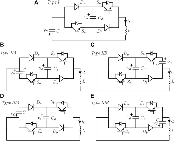
FIGURE 3. Asymmetrical H-bridge circuits. (A) Type I, (B) type IIA, (C) type IIB, (D) type IIIA, and (E) type IIIB.
Each type of AHC contains four switching states. Taking type I as an example, its operating modes are charging, discharging, and bypassing of the decoupling capacitor, as shown in Figure 4. The charge of the decoupling capacitor corresponds to the absorption of ripple power and vice versa to the release (Figures 4A, B). Additionally, there are two freewheeling states that bypass the decoupling capacitor (Figures 4C, D). The redundant switching state provides more possibilities to deduce APD topologies.
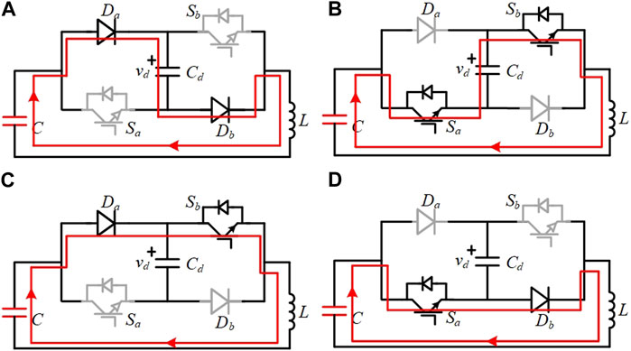
FIGURE 4. Switching states of Type I circuit: (A) State 1: charging Cd (Sa = OFF; Sb=OFF), (B) State 2: discharging Cd (Sa = ON; Sb=ON), (C) State 3: bypassing Cd (Sa = OFF; Sb=ON), and (D) State 4: bypassing Cd (Sa = ON; Sb=OFF).
3 Method and topology synthesis
This section firstly introduces six basic topology synthesis methods by taking type I AHC as an example. Then, through these six methods, other APD topologies based on the AHCs are summarized and developed, as shown in Figure 6.
The basic principle of synthesizing integrated APD converters is divided into replacement and insertion, as shown in Figure 5. The former replaces the diode (Da or Db) or switch (Sa or Sb) in AHC with a diode-bridge rectifier (DBR), a single-phase CSR, a single-phase current source inverter (CSI), or a single-phase VSI. The latter is also feasible to synthesize a new APD converter by inserting a CSR to be in series with the inductor.
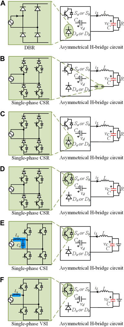
FIGURE 5. Six methods of synthesizing integrated APD converters: (A) Method I: replacing a diode with a DBR, (B) method II: inserting a CSR to be in series with the inductor L, (C) method III: replacing a diode with a CSR, (D) method IV: replacing a switch with a CSR, (E) method V: replacing a switch with a CSI, and (F) method VI: replacing a switch with a VSI.
Taking type I AHC as an example, six methods, which are shown in Figure 6, are introduced as follows.
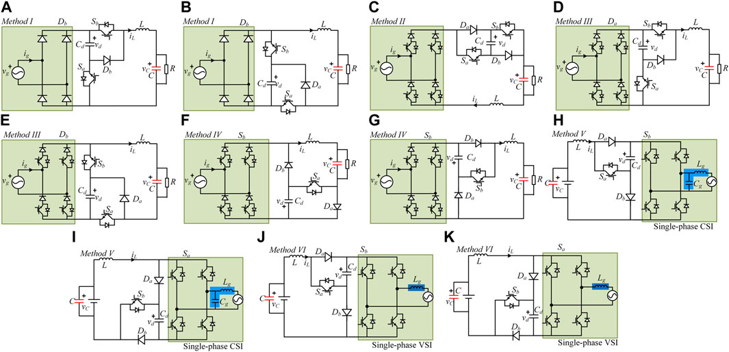
FIGURE 6. Synthesizing converters based on type I AHCs: (A) topology A based on method I, (B) topology B based on method I, (C) topology based on method II, (D) topology A based on method III, (E) topology B based on method III, (F) topology A based on method IV, (G) topology B based on method IV, (H) topology A based on method V, (I) topology B based on method V, (J) topology A based on method VI, and (K) topology B based on method VI.
Method I (Figures 6A, B): The diode Da or Db in the AHC is replaced with a DBR. The topology in Figure 6A was proposed in Ohnuma and Itoh (2014). Its counterpart is shown in Figure 6B, which is deduced in this paper. To ensure normal operation, the rectified diodes should be reversely biased when the switch Sa in Figure 6A or Sb in Figure 6B is turned on. So, the decoupling capacitor voltage vd must be greater than the absolute value of the grid voltage.
Method II (Figure 6C): The CSR is inserted to be in series with the inductor L. The AHC operates dependently with the rectifier. In addition, the decoupling capacitor voltage vd can be smaller than the grid voltage, which indicates that a voltage constraint is released compared with that in the topologies in Figures 6A, B. This circuit topology was proposed in Han et al. (2015) and then applied to PV generation (Zare et al., 2017) and PFC rectifiers (Haider et al., 2019).
Method III (Figures 6D, E): The diode Da or Db in the AHC is replaced with a single-phase CSR. The topology in Figure 6D is identical to that in Figure 6E. It operates at any power factor. However, the decoupling capacitor voltage vd must be greater than the absolute value of the grid voltage.
Method IV (Figures 6F, G): The switch Sa or Sb in the AHC is replaced with a single-phase CSR. The topology in Figure 6F is proposed in Xiong et al. (2020), and the topology in Figure 6G is its counterpart. In both cases, the decoupling capacitor voltage vd is not required to be greater than the absolute value of the grid voltage. However, the sum of the rectified voltage vr and the decoupling capacitor voltage vd should be greater than zero to avoid the diode Da in Figure 6G or Db in Figure 6F being applied to a forward voltage. One highlight is the improvement in reliability. Because there is a natural current path consisting of Cd, Db, L, R, and Da in Figures 6F, G, even if all the switches are turned on or off simultaneously, neither a short circuit nor an open circuit will happen.
Method V (Figures 6H, I): The switch Sa or Sb in AHC is replaced with a single-phase CSI. The topology in Figure 6H is proposed in Ohnuma et al. (2015). However, the decoupling capacitor voltage vd is required to be greater than the peak grid voltage. Moreover, both circuits only operate on the unit power factor. As an extension, each switch can be in series with a diode to make the inverter have a non-unity power factor (Wang et al., 2021).
Method VI (Figures 6J, K): The switch Sa or Sb in the AHC is replaced with a single-phase VSI. Compared with the topologies in Figures 6H, I, the capacitor Cg in the ac filter is removed, which makes the inverter change into a VSI. This topology is also called qSBI (Gautam and Fulwani, 2019; Nguyen et al., 2019) or CFSI and has received a lot of attention recently. They avoid the risk of straight-through bridge arms, which is similar to the ZSI. Based on the proposed synthesis principle, another circuit topology, which also works like ZSI and is named the switched-boost inverter (SBI) (Mishra et al., 2012; Ravindranath et al., 2013), will be derived in the following section. ZSI, SBI, and CFSI possess some similarities in topologies and operations. Their comparison studies were carried out in Nguyen et al. (2015b) and Davise and Prince (2017).
Similarly, the synthesizing APD topologies based on the other types of AHCs are derived and summarized in Table 1. Table 1 provides a method to reveal the formation process of APD topologies that have been proposed by other researchers. Moreover, it is easy to identify their similarities and differences. Additionally, this method deduces some new topologies. Hence, the proposed method for synthesizing APD topologies is general. It should be noted that if there exists counterparts, only one topology is illustrated in the table to save space.
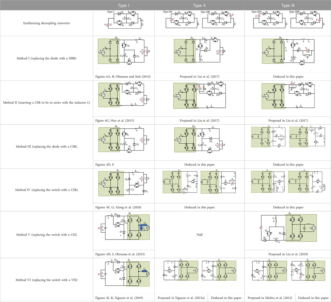
TABLE 1. Summary of integrated active power decoupling converters based on AHCs.
It should be noted that the characteristics of the circuits synthesized using the same method for different types of AHCs are much different. Taking the topologies obtained by using method II as examples, the only difference is the location of the load. However, the voltage and current features are totally different. For the inductor current iL, it equals the load current when synthesized using type I AHC (called method II type I circuit, M2T1C, and other circuits are named in the same manner). However, in M2T2C and M2T3C, the inductor current iL is less than the load current. For output voltage, it is limited to being lower than half the grid peak voltage in M2T1C, while in M2T2C and M2T3C, its value can exceed or fall below half the grid peak voltage. For the decoupling capacitor voltage vd, the constraints are increased in an order from M2T1C and M2T3C to M2T2C. We can refer to the published works of Han et al. (2015) and Liu et al. (2017) for more details. The characteristics of different topologies provide more choices for users. Engineers can choose a topology with suitable characteristics for their specific needs.
More interestingly, the proposed general method to synthesize APD topologies presents good extension performance to derive other circuits, which will be introduced in the following section.
4 Extension to other topologies
This section will demonstrate the extensibility of the proposed topology synthesis methods. It is reflected in two aspects. The first aspect is to deepen the integration of the devices, and the second aspect is to modify the AHC.
For the first extension, more switches or diodes are replaced by the rectifier/inverter. Take CSR as an example, a switch and a diode are merged within a single-phase CSR by horizontal or vertical substitution. The horizontal merging is shown in Figure 7A; the diode Da and switch Sb are merged by the diode and switch on the same bridge arm in the CSR. If a switch and a diode are added to be in series with the diode Db and the switch Sa, respectively, then the decoupling capacitor voltage vd can be shaped into the AC form that is reported in Vitorino et al. (2014). Furthermore, the vertical merging is shown in Figure 7B; the diode Db and switch Sb are merged by the lower switching devices in the CSR. This case saves a switch. However, the decoupling capacitor voltage vd must be greater than the peak grid voltage. More details can be found in Liu et al. (2016).
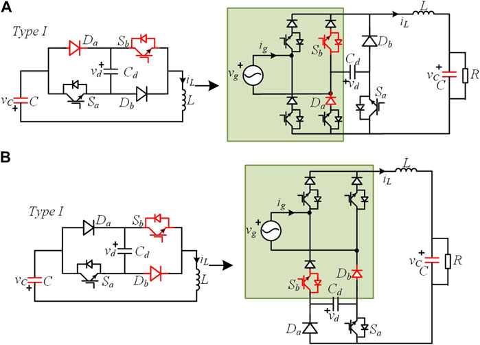
FIGURE 7. Integrated CSR via horizontal replacement (A) and vertical replacement (B).
For the second extension, the AHCs are modified, and three examples are given. First, the modified AHC is shown in Figure 8A, which is obtained by exchanging the locations of the switch Sa and the diode Da in type II AHC. It should be noted that the decoupling capacitor voltage vd must be less than the output voltage. By inserting a DBR to be in series with Sa, an APD topology is obtained, as shown in Figure 8A, which is proposed in Qi et al. (2019a) and called a single-phase three-level flying-capacitor PFC rectifier. Its highlight is the low voltage stress for power devices due to vd ≤ (vc+|vg|). However, it is only suitable for low-power applications to avoid adopting a large decoupling capacitor. Second, for M1T1C, the voltage vd has to be larger than the grid peak voltage, which leads to high voltage stress. To break this limitation, a modified AHC that adds a switch Sc and a diode Dc is shown in Figure 8B. This topology is reported in Qi et al. (2019b) and called a single-phase three-level flying-capacitor buck PFC rectifier. Third, the diodes in type I AHC are both replaced with active switches, as shown in Figure 8C. By inserting a VSI in series with the switch Sb, a two-stage inverter with power decoupling capability is obtained (Watanabe et al., 2018). Obviously, based on the modified AHC in Figure 8C and the synthesis method, many other APD topologies can be further deduced (Zhou et al., 2020; Qi et al., 2021).
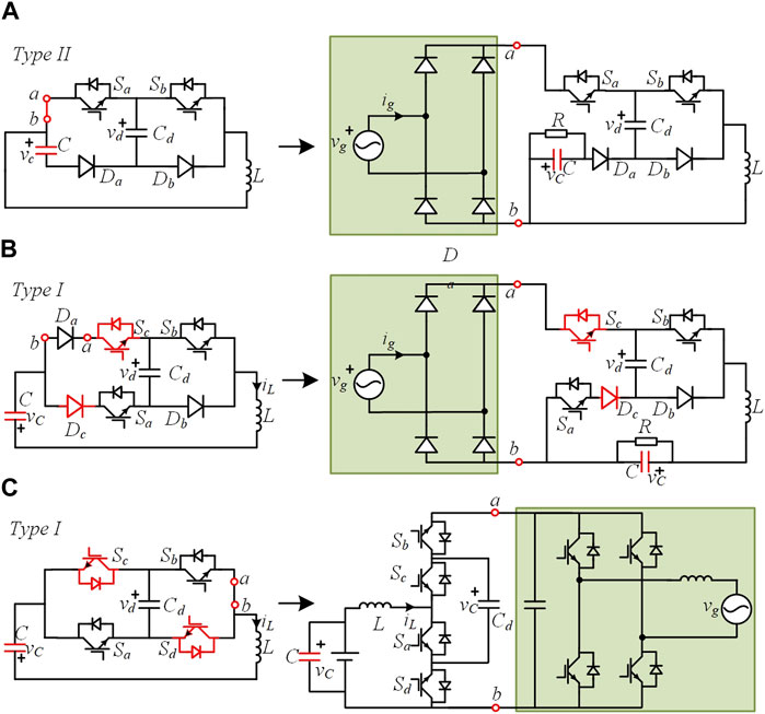
FIGURE 8. Modified type II AHC and one of its synthesizing decoupling circuit (A); modified type I AHC circuits and their synthesizing decoupling circuits (B) and (C).
5 Experimental case study
In this section, an experimental prototype based on the deduced M3T1 topology circuit, as shown in Figure 9, is built for experimental verification. The applied grid voltage is 110 Vrms/50 Hz. The LC filters are 10 μF and 0.6 mH, the dc link inductor L is 5 mH, the load R is 5 Ω, the decoupling capacitor Cd is 60 μF, the load filter capacitor C is 10 μF, and the switching frequency is 20 kHz. The commonly used control strategy for APD capacitors is adopted, as shown in Figure 10. As observed, the averaged value of the decoupling capacitor voltage, which is obtained using a moving average filter (MAF), is regulated by controlling the switches S1-S4 (control the power dragged from the grid). Furthermore, the dc link current is regulated by controlling switches Sa and Sb. The control is realized using the digital signal processor (DSP) TMS320F28335 and the FPGA EP2C8T144C8N. The DSP is responsible for implementing the proposed control strategy and transmitting the duty ratios to the FPGA. The FPGA is used to generate the PWM signals.
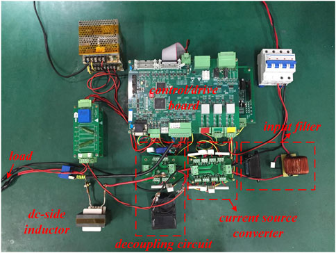
FIGURE 9. Photograph of the prototype.
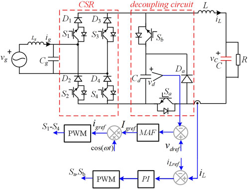
FIGURE 10. Main circuit of the M3T1 topology and its control strategy.
Figure 11 shows the experimental waveforms under the unit power factor. From top to bottom, the waveforms are the dc link current iL, decoupling capacitor voltage vd, and the grid voltage/current vg/ig. At the beginning, the decoupling function is not activated, the switch Sb is always turned off, and Sa is always turned on. It can be found that the dc link current iL presents a large fluctuation with a double-line frequency. What’s worse, the grid current ig is distorted. After enabling the decoupling, the dc link current iL becomes smooth. In addition, the decoupling capacitor voltage vd has a large ac component with a frequency of 100 Hz due to buffering the double-line frequency ripple power. The measured THD of the grid current is only 3.3%, and the measured conversion efficiency is 84.6%.
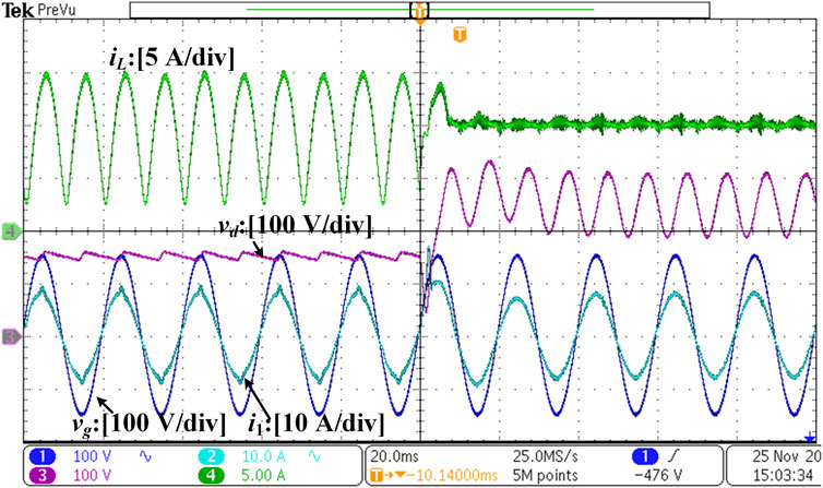
FIGURE 11. Experimental waveforms under the unit power factor.
Figure 12 shows the experimental results when the grid current leads/lags the grid voltage by π/6. As observed, the constant dc link current and sinusoidal grid current are obtained. Moreover, the proposed topology has the capability to control the reactive power under the premise of ensuring the quality of the grid current and the dc link current.
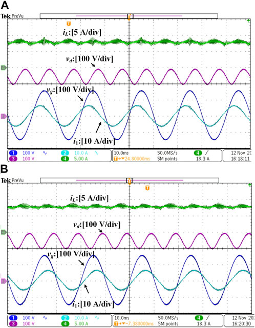
FIGURE 12. Experimental waveforms when the grid current leads the grid voltage with 30° (A) and lags the grid voltage with 30° (B).
Figure 13 shows the experiments with step references to show the dynamic response. As shown in Figure 13A, when the dc link current reference decreases from 10 A to 5 A, the DC-link current tracks its reference immediately and the voltage of the decoupling capacitor becomes smaller. Figure 13B shows the results of the reverse process. In both cases, no obvious voltage/current peak/valley happens.
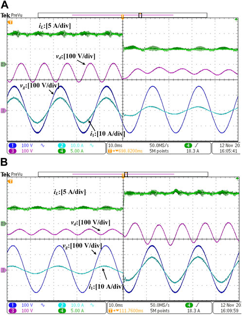
FIGURE 13. Transient experimental waveforms. (A) Dc current reference is suddenly changed from 10 A to 5 A. (B) Dc current reference is suddenly changed from 5 A to 10 A.
6 Conclusion
In this paper, a general method is proposed to synthesize APD topologies based on AHCs. The main construction idea is to insert a rectifier/inverter into AHCs or replace the switch/diode in the AHCs with a rectifier/inverter. It is shown that the general method can be used to deduce many existing decoupling circuits and new circuits. In addition, it presents a good extension by deepening the integration of the devices and modifying the circuit structures of AHCs. An experimental case study based on the deduced M3T1 topology has been carried out to illustrate the feasibility and effectiveness of the proposed topology synthesis method.
Data availability statement
The original contributions presented in the study are included in the article/Supplementary Material; further inquiries can be directed to the corresponding author.
Author contributions
YL: conceptualization, methodology, investigation, data curation, and writing—original draft. YZ: conceptualization, investigation, validation, supervision, and funding acquisition. LY: conceptualization, methodology, visualization, writing—review and editing, and funding acquisition. All authors contributed to the article and approved the submitted version.
Funding
This work was supported in part by the science and technology innovation Program of Hunan Province 2023RC3033, in part by the National Natural Science Foundation of China under Grant 52277209, and in part by the Central South University Innovation-Driven Research Programme under Grant 2023CXQD020.
Conflict of interest
The authors declare that the research was conducted in the absence of any commercial or financial relationships that could be construed as a potential conflict of interest.
Publisher’s note
All claims expressed in this article are solely those of the authors and do not necessarily represent those of their affiliated organizations, or those of the publisher, the editors, and the reviewers. Any product that may be evaluated in this article, or claim that may be made by its manufacturer, is not guaranteed or endorsed by the publisher.
Supplementary material
The Supplementary Material for this article can be found online at: https://www.frontiersin.org/articles/10.3389/felec.2023.1250099/full#supplementary-material
References
Davise, A., and Prince, A. (2017). “Comparative study between ZSI, SBI and CFSI,” in 2017 IEEE International Conference on Power, Control, Signals and Instrumentation Engineering (ICPCSI)), Chennai, India, 21-22 September 2017, 1077–1081.
Fontes, G., Turpin, C., Astier, S., and Meynard, T. A. (2007). Interactions between fuel cells and power converters: influence of current harmonics on a fuel cell stack. Ieee Trans. Power Electron. 22 (2), 670–678. doi:10.1109/tpel.2006.890008
Gautam, A. R., and Fulwani, D. (2019). Adaptive smc for the second-order harmonic ripple mitigation: a solution for the micro-inverter applications. Ieee Trans. Power Electron. 34 (8), 8254–8264. doi:10.1109/tpel.2018.2882646
Haider, M., Bortis, D., Kolar, J. W., and Ono, Y. (2019). “Novel single-phase Buck+Boost PFC rectifier with integrated series power pulsation buffer,” in 2019 10th International Conference on Power Electronics and ECCE Asia (ICPE 2019 - ECCE Asia)), Busan, Korea (South), 27-30 May 2019.
Han, H., Liu, Y. L., Sun, Y., Su, M., and Xiong, W. J. (2015). Single-phase current source converter with power decoupling capability using a series-connected active buffer. Iet Power Electron. 8 (5), 700–707. doi:10.1049/iet-pel.2014.0068
Hu, H. B., Harb, S., Kutkut, N., Batarseh, I., and Shen, Z. J. (2013). A review of power decoupling techniques for microinverters with three different decoupling capacitor locations in PV systems. Ieee Trans. Power Electron. 28 (6), 2711–2726. doi:10.1109/tpel.2012.2221482
Kim, H., and Shin, K. G. (2012). Desa: dependable, efficient, scalable architecture for management of large-scale batteries. Ieee Trans. Industrial Inf. 8 (2), 406–417. doi:10.1109/tii.2011.2166771
Li, S. N., Qi, W. L., Tan, S. C., and Hui, S. Y. R. (2017). A single-stage two-switch PFC rectifier with wide output voltage range and automatic AC ripple power decoupling. Ieee Trans. Power Electron. 32 (9), 6971–6982. doi:10.1109/tpel.2016.2622980
Li, S. N., Tan, S. C., Lee, C. K., Waffenschmidt, E., Hui, S. Y., and Tse, C. K. (2016). A survey, classification, and critical review of light-emitting diode drivers. Ieee Trans. Power Electron. 31 (2), 1503–1516. doi:10.1109/tpel.2015.2417563
Liu, Y. L., Su, M., Liu, F. L., Zheng, M. H., Liang, X., Xu, G., et al. (2019). Single-phase inverter with wide input voltage and power decoupling capability. Ieee Access 7, 16870–16879. doi:10.1109/access.2019.2895350
Liu, Y. L., Sun, Y., and Su, M. (2016). Active power compensation method for single-phase current source rectifier without extra active switches. Iet Power Electron. 9 (8), 1719–1726. doi:10.1049/iet-pel.2015.0899
Liu, Y. L., Sun, Y., and Su, M. (2017). Family of two-port switching networks with ripple power decoupling and output voltage step-up functions. Iet Power Electron. 10 (10), 1175–1182. doi:10.1049/iet-pel.2016.0411
Mishra, S., Adda, R., and Joshi, A. (2012). Inverse watkins-johnson topology-based inverter. Ieee Trans. Power Electron. 27 (3), 1066–1070. doi:10.1109/tpel.2011.2177278
Nguyen, M. K., Le, T. V., Park, S. J., and Lim, Y. C. (2015a). A class of quasi-switched boost inverters. Ieee Trans. Industrial Electron. 62 (3), 1526–1536. doi:10.1109/tie.2014.2341564
Nguyen, M. K., Lim, Y. C., and Park, S. J. (2015b). A comparison between single-phase quasi- Z-source and quasi-switched boost inverters. Ieee Trans. Industrial Electron. 62 (10), 6336–6344. doi:10.1109/tie.2015.2424201
Nguyen, M. K., Tran, T. T., and Lim, Y. C. (2019). A family of PWM control strategies for single-phase quasi-switched-boost inverter. Ieee Trans. Power Electron. 34 (2), 1458–1469. doi:10.1109/tpel.2018.2831674
Ohnuma, Y., and Itoh, J. I. (2014). A novel single-phase buck PFC AC-DC converter with power decoupling capability using an active buffer. Ieee Trans. Industry Appl. 50 (3), 1905–1914. doi:10.1109/tia.2013.2279902
Ohnuma, Y., Orikawa, K., and Itoh, J. (2015). A single-phase current-source PV inverter with power decoupling capability using an active buffer. Ieee Trans. Industry Appl. 51 (1), 531–538. doi:10.1109/tia.2014.2347312
Qi, W. L., Li, S. A., Tan, S. C., and Hui, S. Y. (2019a). A single-phase three-level flying-capacitor PFC rectifier without electrolytic capacitors. Ieee Trans. Power Electron. 34 (7), 6411–6424. doi:10.1109/tpel.2018.2871552
Qi, W. L., Li, S. N., Yuan, H. W., Tan, S. E. C., and Hui, S. Y. E. (2019b). High-power-density single-phase three-level flying-capacitor buck PFC rectifier. Ieee Trans. Power Electron. 34 (11), 10833–10844. doi:10.1109/tpel.2019.2896585
Qi, W. L., Wang, M. H., and Li, S. N. (2021). Transformerless three-level flying-capacitor step-up PV micro-inverter without electrolytic capacitors. Ieee J. Emerg. Sel. Top. Circuits Syst. 11 (1), 49–58. doi:10.1109/jetcas.2020.3039284
Ravindranath, A., Mishra, S. K., and Joshi, A. (2013). Analysis and PWM control of switched boost inverter. Ieee Trans. Industrial Electron. 60 (12), 5593–5602. doi:10.1109/tie.2012.2230595
Sun, Y., Liu, Y. L., Su, M., Xiong, W. J., and Yang, J. (2016). Review of active power decoupling topologies in single-phase systems. Ieee Trans. Power Electron. 31 (7), 1–4794. doi:10.1109/tpel.2015.2477882
Vitorino, M. A., Wang, R. X., Correa, M. B. D., and Boroyevich, D. (2014). Compensation of DC-link oscillation in single-phase-to-single-phase VSC/CSC and power density comparison. Ieee Trans. Industry Appl. 50 (3), 2021–2028. doi:10.1109/tia.2013.2284300
Wang, M. H., He, Y. F., Jia, Y. W., and Xu, Z. (2021). A power-decoupled current-source inverter for PV energy harvest and grid voltage regulation. Ieee Trans. Industrial Electron. 68 (10), 9540–9549. doi:10.1109/tie.2020.3026264
Watanabe, H., Sakuraba, T., Furukawa, K., Kusaka, K., and Itoh, J. (2018). Development of DC to single-phase AC voltage source inverter with active power decoupling based on flying capacitor DC/DC converter. Ieee Trans. Power Electron. 33 (6), 4992–5004. doi:10.1109/tpel.2017.2727063
Xiong, W. J., Liu, Y. L., Lin, Z. H., Sun, Y., and Su, M. (2020). Single-phase current source converter with high reliability and high power density. Iet Power Electron. 13 (6), 1218–1226. doi:10.1049/iet-pel.2019.1236
Zare, M. H., Mohamadian, M., and Beiranvand, R. (2017). Single-stage AC module with series power decoupling capability for connecting PV to a single-phase power grid. Iet Power Electron. 10 (5), 517–524. doi:10.1049/iet-pel.2016.0349
Keywords: active power decoupling, H-bridge circuit, double-line frequency ripple power, single-phase systems, topology
Citation: Liu Y, Zuo Y and Yuan L (2023) Topology synthesis of integrated active power decoupling converters using asymmetrical H-bridge circuits. Front. Electron. 4:1250099. doi: 10.3389/felec.2023.1250099
Received: 29 June 2023; Accepted: 14 August 2023;
Published: 08 September 2023.
Edited by:
Yuqi Wei, Xi’an Jiaotong University, ChinaCopyright © 2023 Liu, Zuo and Yuan. This is an open-access article distributed under the terms of the Creative Commons Attribution License (CC BY). The use, distribution or reproduction in other forums is permitted, provided the original author(s) and the copyright owner(s) are credited and that the original publication in this journal is cited, in accordance with accepted academic practice. No use, distribution or reproduction is permitted which does not comply with these terms.
*Correspondence: Liang Yuan, bGlhbmcueXVhbkBjc3UuZWR1LmNu