 Liang Yuan
 Jian Zhang
 Zheng Liang1,2
- 1School of Automation, Central South University, Changsha, Hunan, China
- 2Hunan Provincial Key Laboratory of Power Electronics Equipment and Grid, Central South University, Changsha, Hunan, China
- 3China Electric Power Research Institute, Beijing, China
- 4Jiangsu Power Transmission and Transformation Co., Ltd., Nanjing, Jiangsu, China
The utilization of power electronic-based converters is gaining momentum across a wide spectrum of industries. However, modern power electronic converters operate at higher frequencies compared to conventional power electronic converters, which can lead to higher rates of change in voltage and current during phase switching, and thus potentially produce more severe conducted and radiated electromagnetic interference (EMI). Their electromagnetic compatibility (EMC) has become a critical research topic, and EMI in high-frequency power electronic-based converters is more complex than that in conventional converters. This review presents a comprehensive survey of recent advancements, EMI design, and analysis of modern power electronic-based converters, focusing on the sources and mechanisms of both conducted and radiated EMI, and mitigating techniques. This review also covers the impact of topology optimization, control strategy design, and packaging design on EMC performance. Addressing emerging EMI issues in modern power electronic device-based converters is essential for ensuring safe and reliable operations. Through strategic design optimization and the implementation of EMI mitigation strategies, modern converters can seamlessly be integrated into diverse applications, offering improved EMI performance as a hallmark of their versatility.
1 Introduction
With the rapid development of modern power electronic technology, power conversion using power electronic converters has become more widespread. The control of circuits using semiconductor switches instead of conventional mechanical switches improves power efficiency (Vrankovic et al., 2022). However, power electronic devices can lead to a higher rate of change in voltage and current during switching on and off processes, thus generating electromagnetic interference (EMI) (Zhang et al., 2021; Wang et al., 2022; Ma et al., 2023a). EMI not only affects the normal operation of surrounding equipment but also affects the device itself. Therefore, the suppression of EMI and the improvement of electromagnetic compatibility (EMC) have become essential (Sun et al., 2020).
Electromagnetic interference generated by power electronic devices is divided into conducted and radiated EMI based on the coupling pathway and electromagnetic field propagation (Natarajan et al., 2020). Conducted EMI refers to the coupling of signals from one electrical network to another through a conductive medium, and its frequency is below 30 MHz (Wang et al., 2022). Common-mode (CM) electromagnetic interference and differential-mode (DM) electromagnetic interference are categorized according to the different ways of conducting EMI (Jiang et al., 2019; Li et al., 2023). Common-mode EMI is mainly caused by the interaction between the rapidly changing voltage and parasitic capacitance to the ground of the switching converter via the ground distribution parameter, the phase line (Cao et al., 2023), and the ground plane to form a circuit loop, resulting in high-frequency oscillations with a typical frequency generally greater than 5 MHz. Differential-mode electromagnetic interference is mainly caused by pulsed current, when the rapidly changing current is affected by stray inductance, forming a circuit path between the phase lines. The frequency of oscillations is generally less than or equal to 5 MHz (Natarajan et al., 2020). Common- and differential-mode EMIs may be generated simultaneously in some circuits (Helton et al., 2023). Radiated EMI is the coupling of signals to another electrical network through space (Seifi et al., 2021; Ma et al., 2023a). The radiated EMI inside the converter valve mainly comprised differential-mode current and common-mode current in the circuits of IGBTs and their control boards, and the CM current electromagnetic interference is dominant (Zhou et al., 2022; Fan et al., 2023). When compared with conducted EMI, radiated EMI’s stray inductance and capacitance parameters are more complicated to calculate, so the modeling and analysis of radiated EMI become more difficult (Ma et al., 2022a).
Electromagnetic interference is mainly determined by three factors, namely, the interference source, coupling path, and sensitive devices, as shown in Figure 1. There are two ways of coupling, namely, conductive coupling and radiative coupling; the former is obtained through physical connections such as wires, cables, transmission lines, and PCB routing (Natarajan et al., 2020), and the latter, through free space and dielectrics, including energy coupling of electric and magnetic fields. The existing reviews of EMI in power electronic converters have typically focused on specific converter types, such as two-level, three-level, or modular multilevel converters. These reviews have provided valuable insights into EMI’s impact mechanisms and corresponding mitigation measures, often from perspectives including circuit topology, switching characteristics, and circuit parameters like line cables, inductors, and capacitors (Li et al., 2023; Zhang and Wang, 2022; Chen et al., 2021). However, these studies tend to concentrate on a particular converter type, thus offering a limited view of the broader spectrum of EMI challenges inherent in modern power electronic-based converters.
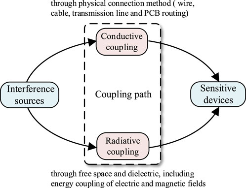
FIGURE 1. Electromagnetic interference coupling mechanism.
To fill this research gap, this paper presents a comprehensive review of EMI challenges in modern power electronic-based converters. It not only summarizes the modeling methods for conducted and radiated EMI in the field of power electronics but also covers the EMI characteristic analysis of different types of converters. Additionally, the paper categorizes mitigation methods based on application objectives and working principles, emphasizing the optimization of control strategies, EMI filter design, and other methods. The study also compares the limitations to existing EMI mitigation techniques. This paper is designed to provide profound insights into the emerging EMI challenges in power electronic-based converters, aiming to advance the understanding of EMI issues and catalyze innovative solutions.
The rest of the paper is organized as follows: Section 2 describes the modeling methods and characteristics of conducted and radiated EMI in modern power electronic devices. Section 3 introduces the testing methods for electromagnetic interference. Section 4 proposes mitigation techniques for the causes and propagation pathways of electromagnetic interference, and Section 5 provides conclusion to this paper and analyzes the directions for future research.
2 Modeling and characteristic analysis of power electronic-based EMI
The differences in EMI among different power levels, applications, and various types of power supply devices primarily manifest in environmental requirements, electronic device switching frequencies, and the potential presence of specific interference sources (Srivastava and Seshadrinath, 2023). Power supply device types include switching power supplies, inverters, transformers, and more (Ma et al., 2023b). Switching power supplies, characterized by high switching frequencies, have the potential to generate extensive radiation and conducted EMI. Typically, EMI interference from switching power supplies is reduced through the use of filters and shielding. Inverters, which generate high-frequency modulation signals, typically use techniques like motor coil shielding and filtering to mitigate EMI issues. Transformers, on the other hand, may induce conducted EMI when switching magnetic fields (Zhang et al., 2021). Therefore, specialized designs and materials are often utilized to decrease EMI in transformer-based systems. Due to the switching frequencies of power electronic devices reaching several tens of kilohertz, more severe radiation and conducted EMI may occur. In contrast, low-frequency, high-power electronic devices with lower switching frequencies tend to have relatively minor EMI issues.
This paper primarily models and analyzes the EMI of modern power electronic converters, which is beneficial for proposing subsequent EMI mitigation techniques. The energy of electromagnetic interference is emitted by electromagnetic interference sources. During the commutation process of normally operating power electronic devices, significant changes in voltage and current rates occurred (Hosseinipour et al., 2018), affecting the normal operation of other devices through conduction and radiation coupling methods.
2.1 Modeling and characteristic analysis of conducted EMI
2.1.1 Modeling of conducted EMI
Conducted EMI modeling methods can be divided into two main categories: the time-domain EMI modeling method and frequency-domain EMI modeling method. The time-domain approach focuses on the broadband modeling of all power and passive devices in the system, which requires detailed information on all components, including the stray impedance and physical structure. It is critical to use a very small simulation step in the simulation process to guarantee accuracy, which leads to typically long simulation time. An accurate description of the dynamic process in power switches is key to the time-domain EMI modeling approach. Ma et al. (2023a) compared the switching characteristics of wide-bandgap devices and silicon metal–oxide–semiconductor field-effect transistors (MOSFETs), along with their impact on radiated EMI. It also provides an overview of research on radiated EMI both above and below 30 MHz. Wang et al. (2022) primarily investigated the characteristics of EMI sources in a modular multilevel converter (MMC) by analyzing MMC’s topology, modulation methods, and the dynamic switching processes of power electronic devices. It summarizes the standard assessment and modeling methods for EMI emissions in MMC. This paper systematically and comprehensively summarizes theoretical modeling methods for both conducted and radiated EMI. EMI modeling methods in the field of power electronic converters include the direct measurement method, finite element method, and feature modeling method.
The direct measurement method (DM) uses an impedance analyzer to directly measure the amplitude frequency response characteristic curves and phase frequency response characteristic curves of each active/passive component in the system (Zhuolin et al., 2017). A high-accuracy frequency equivalent model is formed by fitting the curve with a combination of resistance, inductance, and capacitance, but the accuracy of the model decreases at very high frequencies, such as those above tens of megahertz. The finite element method (FEM) usually establishes the 3D model of each component in finite element analysis software (Chen et al., 2018; Wu et al., 2023), utilizing the finite element calculation of the software application to determine the description matrix of the device parameters and combining with the physical model to determine the high-frequency equivalent model. This method is complex, time-consuming, and highly dependent on software and computer performance (Kumaresan et al., 2021). The feature modeling method (FM), which is generally used in the modeling of active components such as power switches (Hillenbrand et al., 2017; Kharanaq et al., 2020), imports the basic parameters of the device in Saber, ANSYS, and other software programs, along with the input/output characteristic curve and the thermal characteristic curve. The software will determine the device’s model with equivalent ports based on the calculations of its switching characteristics, voltage and current conversion characteristics, and the dynamic and static characteristics of the internal charge. The modeling method has some errors because the actual parameters of each device are not exactly the same. The time-domain EMI prediction methods for three-phase two-level converter EMI are mature, and these methods were able to achieve the prediction results with a maximum error of less than 6 dB in the range of 30 MHz (Zhuolin et al., 2017).
The frequency-domain modeling approach replaces the interference sources with a mathematical model, avoiding the physical modeling of switching devices. There are two types of frequency-domain modeling methods. One is behavioral modeling (BM) (Wang et al., 2023), which is based on the behavior of the system. Another is the filter-design-oriented modeling (FDOM) (Zhang et al., 2017a; Kim et al., 2017), which is based on the design of filters. BM does not focus on EMI’s generation mechanism and conduction path inside the power electronic converters. Instead, the power conversion part of the converter is equivalent to an active multi-port “black box” circuit (Negri et al., 2022; Wan et al., 2023). The three-port active equivalent circuit was proposed to replace the AC output side of a power electronic converter by choosing the appropriate external insertion circuits and calculating interference sources and internal impedance parameters (Gahfif et al., 2019). The model can accurately predict the electromagnetic interference in 100 active dual-port equivalent circuit bands of CM and DM interferences in the three-phase two-level converter and can predict the electromagnetic interference at both input and output terminals. The experiment shows that the model is able to predict EMI in the frequency range of 40 MHz in a way that is nearly the same as that in the actual measurements. Although the BM method can achieve quite high EMI prediction accuracy, it relies on the actual measurement data and has no practical physical meaning.
FDOM is based on the filter design considering the conducted sources and the conduction paths separately. There are two forms of CM and DM interferences in the system, and early filter modeling completely separated them. The replacement of the interference source with an ideal trapezoidal pulse sequence limits the accuracy of the prediction (Niklaus et al., 2021). The accuracy of system EMI modeling is then improved by replacing the interference source with a trapezoidal pulse train whose slope depends on the current flowing through the switching tube (Kim et al., 2017). The theory of strong and weak inductive coupling of CM interference equivalent circuits based on parallel SiC MOSFETs has been proposed for the inductive coupling effect of parasitic inductance between parallel branches (Chen et al., 2021). In recent years, CM and DM equivalent circuits are no longer considered separately but are considered the mixed-mode electromagnetic interference in the system (Zhang et al., 2017a). The FDOM prediction method ignores parameters such as switching tube junction capacitance, bus lead inductance, and switching module lead inductance. It leads to the inability to predict the switching tube ringing effect and the poor prediction accuracy of the ringing effect in three-phase converters (Jiang et al., 2019). FDOM also fails to reflect characteristics such as trailing currents and time-varying parasitic capacitance of power switches. The sources of interference in FDOM and conduction paths have a clear physical meaning. FDOM is suitable for less accurate predictions.
2.1.2 Characteristic analysis of conducted EMI
EMI generated by power electronic equipment is mainly caused by the following: 1) the change of voltage. Sudden voltage changes can generate charging or discharging currents in the stray distributed capacitors of the drive and main circuits, and their current transient pulses can cause serious electromagnetic disturbance to the surrounding power system. 2) The change of current. At the instant of power electronic turn-on and turn-off, the rapid change of current will induce a voltage in the stray capacitor, and the current loop with larger current variations will radiate EMI to the space around it. 3) Control circuits. High-frequency pulsed signals generated by control circuits can also generate EMI. 4) Non-linear components and the circuits they form, which distort the signals in the circuit.
Conducted EMI is also affected by topology optimization, control strategies, device characteristics, and package design (Wang et al., 2022). A new integrated active EMI filter (AEF) topology, which can attenuate CM and DM noise simultaneously, is proposed (Zhou et al., 2022), requiring fewer components and a DC power supply. The topology optimization method for the magnetic core structure for π-type filter circuits is designed and captures magnetic coupling effects with the use of three-dimensional electromagnetic field analysis which can remove the noise generated by conducted and induced current. It significantly improves the performance of EMI filters (Takahashi et al., 2021). In phase-shifted full-bridge converters with input current steering, the use of a clamping capacitor as a built-in second voltage source reduces di/dt noise and improves EMI performance (Yen and Chao, 2022), and dv/dt noise attenuation is achieved by zero-voltage switching operation. Some of the spurious parameters in power electronic converters are not constant. Since the IGBT module has a heating effect, the values of the spurious parameters around it may exhibit thermally variable characteristics (Zhuolin et al., 2017). In order to address the inability to dynamically change the values of model parameters, a multi-physics field time-domain EMI prediction considering time-varying, frequency-varying, and thermally varying characteristics of critical components’ high-frequency models is required. The common-mode interference introduces a mixed mode (MM) in the presence of additional differential-mode component factors, which leads to EMI. Furthermore, the modeling of MMC-conducted EMI with different sub-module switching states is affected by the sub-module heat sink connection methods (Sun et al., 2023). The CM equivalent circuit analysis of half-bridge power modules with different parasitic inductances shows that CMFs’ integrated circuits provide better noise attenuation in the high-frequency range (Wang et al., 2023).
2.2 Modeling and characteristic analysis of radiated EMI
2.2.1 Modeling of radiated EMI
The high-speed change in voltage and current of semiconductor devices during the commutation process will excite changes in the electric and magnetic fields. The changing magnetic field is generated alternately with the electric field (Ma et al., 2023a), forming electromagnetic waves that radiate into free space. The high-frequency current loop formed by the modern switching devices is a typical magnetic field source. Radiated EMI is classified into near-field and far-field radiation (Lai et al., 2023). The method of moments (MoM) is used to model far-field EMI radiation, and the prediction methods of far-field radiation are usually based on antenna theory (Haider et al., 2018; Wang et al., 2023). The finite element method is more accurate than the direct measurement method when extracting parameters (Xu et al., 2021).
R Thomas and colleagues proposed the idea of using dipole models to predict the far-field radiation level of switching power supplies in 2000 (Thomas et al., 2000), and theoretically demonstrated the effectiveness of the far-field radiation prediction through a combination of circuit simulation, spectral analysis, and simplified antenna modeling. The frequency characteristic of radiated EMI is expressed as the product of the inverter voltage and the load circuit gain frequency characteristic, with the load circuit acting as an antenna. The voltage rise time of the switching device and the size and shape of the load circuit affect EMI to a large extent. In the research on radiation modeling of components, it is necessary to first establish the three-dimensional models of capacitors and inductors in CST software (Takahashi et al., 2017), and use finite element simulation to achieve three-dimensional electromagnetic field modeling and radiation characteristic analysis of circuit components. The effect of near-field radiated interference generated by components on the performance of EMI filters can be analyzed using the frequency domain solver of CST. By studying the radiated interference mechanism of the flyback converter from the point of view of the equivalent circuit model, common-mode noise is found to be an important reason for radiated interference generation. EMI is radiated through the input and output cables to form an equivalent antenna (Li et al., 2018). The antenna radiation model is established on this basis, and the original model of the transformer with six capacitors is simplified to a model with two capacitors. The expression for the common-mode noise is derived, which is used for the prediction of common-mode noise and far-field radiation of the flyback converter (Zhang et al., 2017b; Sun et al., 2023). The inclusion of a PCB ground impedance model can improve the accuracy when studying the radiated EMI of active clamped flyback (ACF) power converters (Ma et al., 2023b). The resolution bandwidth’s impact on radiated EMI should be considered because the impedance of critical PCB traces above 30 MHz for radiated EMI analysis cannot be ignored when the switching frequency of the power converter is smaller than 240 kHz (Ma et al., 2022a; Yao et al., 2022).
2.2.2 Characteristic analysis of radiated EMI
When studying the EMI of Buck converters in printed circuit boards, it has been found that the length of the circuit wire has a greater effect on the intensity of the far-field radiation, and that the CM current in the circuit wire, not the DM current, is the main cause of the radiated electric field (Han et al., 2017; Cao et al., 2023). Considering an active clamped flyback converter with a long power cable as an example, radiated EMI is affected by the switching frequency, and the impedance of the CM choke when it is placed on PCB affects the near-field coupling of the noise (Ma et al., 2022b). The relationship between the resonant frequency and switching noise of a switching power supply can be studied using FEM simulation software. PCB-based converters often lead to higher parasitic capacitance coupling. CM inductors with high common-mode impedance or equivalent parasitic capacitance between low inputs and outputs can suppress CM noise (Vrankovic et al., 2022). The package design considers the half-bridge PFC converter radiating EMI noise (Yoshida et al., 2023; Avinash and Gupta, 2023), and it can reduce the radiated interference by inserting decoupling capacitors to clamp the current path. The closer to the high-frequency wide-bandgap (WBG) packaged power module the integrated π-common-mode filter (π-CMF) is (Zhang and Wang, 2022), the greater the noise attenuation. By comparing the radiated EMI effects of wide bandgap devices (WBGs) and Si devices (Ma et al., 2023a), more severe voltage/current ringing is observed in WBG devices’ applications than in Si devices’ applications. Enhancing EMC through packaging technology can specifically be classified into three categories: improved wire bonding structures, planar interconnection structures, and hybrid packaging structures. Improved wire bonding structures offer a simple process but fail to effectively reduce the module’s parasitic inductance (Jia et al., 2022). When the effect of ringing is severe, the parasitic inductance has a greater effect on radiated EMI. The impedance characteristic of inductors and capacitors affects the radiated EMI prediction of circuits, and the CM inductor and Y-capacitor design are explored in detail for EMI reduction for specific circuits (Zhang and Wang, 2022). Different filter structures have different effects on radiated EMI. Adding a phase modular buck–boost Y inverter to a two-stage, three-phase, silicon insulated-gate bipolar transistor voltage source inverter can help avoid the use of shielded cables to reduce EMI emissions (Menzi et al., 2021).
Since the two types of EMI conducted and radiated interference impact mechanisms are different, their research methodologies also differ. Conducted radiation is generated through physical connections such as wires and cables, and it is beneficial to improve the prediction accuracy if all parts of the system are modeled as comprehensively as possible. Radiation interference caused by space and dielectric generated EMI, which leads to direct measurement, is more difficult, and the radiation EMI coupling mechanism is not clear, leading to the modeling process, and is easy to analyze for certain influencing factors such as stray capacitance and PCB capacitance to the ground, resulting in a lack of systematic and comprehensive analyses. The classifications and methods of EMI are shown in Figure 2. Table 1 shows a comparison of different methods’ performance.

FIGURE 2. Summary of EMI classifications and methods.
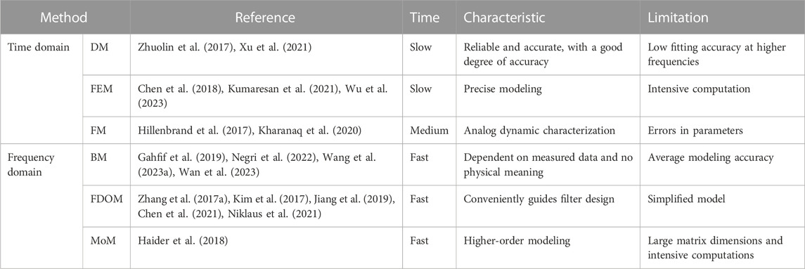
TABLE 1. Comparison of different methods’ performance.
3 Testing and measurement of power electronic-based EMI
There are a large number of power electronic devices in the power system, so the electromagnetic environment is very complex. The EMI level obtained from field measurements comprised the superposition of the electromagnetic interference generated by all the devices in the power system. In addition, on-site measurements can also take into account the influencing factors of the area where the converter station is located, such as the buildings around the converter station, soil parameters, and weather, along with other factors that will have an impact on the propagation of electromagnetic fields in space. Therefore, the measurement results can more comprehensively reflect the EMI characteristics of the power system, thus reflecting the sum of electromagnetic phenomena in the power system. At present, the relevant departments at home and abroad have proposed some standards and guidelines on EMC testing and experimental methods. Whether the EMI measurements are carried out in the actual site or the laboratory, references should be made to the measurement methods and limit values recommended by the standards and guidelines. For conducted EMI and radiated EMI, due to different propagation characteristics of the two, the test and measurement calculation methods adopted are not the same, which will be elaborated in the following paragraphs.
3.1 Testing and measurement of conducted EMI
Power electronic converter conduction electromagnetic interference testing needs to be carried out in accordance with the specified standards; most of the commonly used international electromagnetic compatibility standards are developed by the International Special Committee on Radio Interference (CISPR) and the technical committee on electromagnetic compatibility (TC), both of which are committees under IEC, and the standards are recognized by the international community. Among them, the EMI test standards for frequencies above 9 kHz are mainly formulated by CISPR (Li, 2019). Among the standards formulated by CISPR, CISPR 11 determines the test standards related to conducted EMI for high-power electronic systems and equipment (IrishStandard, 2006), which stipulates that the test band of conducted EMI is from 150 kHz to 30 MHz and determines the interference limit values. CISPR 16 determines the general test methods for conducted EMI, including test equipment, test arrangements, and test points (International Electrotechnical Commission, 2014).
Conducted EMI test equipment generally includes EMI test receivers, artificial networks (ANs), voltage probes, and current probes. EMI test receivers have multiple modes such as peak detection, quasi-peak detection, RMS detection, and average detection. The basic working principle can be briefly summarized as filtering the measured time-domain signal using the internal hardware IF filter, changing the effective bandwidth of the filter through the setting of the bandwidth, detecting the filtered time-domain signal in hardware, considering the peak value, and then taking the value as the interference amplitude at the frequency point. In the usual conducted EMI measurement, the maximum envelope of the interference is desired, so the peak detection mode is often chosen as the standard operating mode of the EMI test receiver, and AN mainly provides a flow path for conducted EMI; at the same time, the impedance in AN provides a standard impedance stabilization network for EMI, and the values of the EMI voltage and the EMI current that flows through AN always satisfy the standard impedance relationship. AN is usually installed between the power supply and the converter or between the load and the converter, and for the consideration of decoupling common-mode interference and differential-mode interference, AN is usually installed on each cable of AC and DC sides, and the models and parameters of multiple ANs are exactly the same. For electromagnetic interference which cannot be measured by AN, it is determined by voltage and current probes, in which the clamp voltage probe needs to be clamped on the test point and the reference ground, and the current probe can be wrapped around the conductor to be tested.
The test layout for conducted EMI is mainly for the location of the equipment to be tested, the ground plane, AN, and test equipment. According to the CISPR 16 standard, when conducting the conducted EMI test, a metal plate should be prepared as the grounding plate, the grounding plate should be placed on the ground as the reference ground, and the equipment to be tested should not be placed directly on the grounding plate, but should be connected to the grounding plate through the conductor to the grounding point of the piece of equipment to be tested and the distance between the piece of equipment to be tested and the grounding plate should be more than 40 cm. AN can be mounted directly on an earthed metal plate and connected between the power supply and the converter. The enclosure of the power supply and test equipment is connected to the ground of the distribution network, and the equipment is placed directly on the ground. In order to avoid common-mode interference from flowing through the power supply and test equipment through the ground, it can also be considered for installing a filter on the grounding line of the power supply and test equipment, and the main requirements of the test layout for conducted electromagnetic interference are shown in Figure 3.
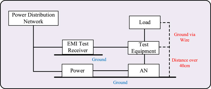
FIGURE 3. Conducted EMI test point diagram.
Test points for conducted EMI include power lines, load lines, signal/control lines, and antenna ports, as shown in Figure 4. The power line test point is between the power supply and the power electronic converter, and usually tests the voltage/current on the standard impedance in AN of the power supply or the current on the connection line between AN and the power electronic converter. The load line test point is between the power electronic converter and the load, and usually tests the voltage/current on the standard impedance in AN on the load side or the current on the connection line between the power electronic converter and AN. The antenna port test points are the pairs of cables in the power electronic converter that can easily form a transmitting antenna, and the current on the antenna port cables is usually tested. The signal/control line test point is the signal/control line inside the power electronic converter, which usually uses the voltage/current probe to test the voltage/current of the signal/control line test point.
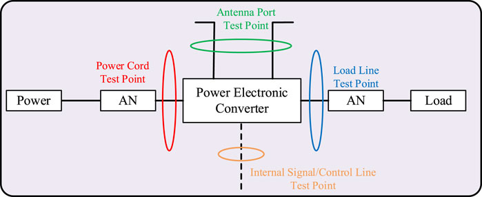
FIGURE 4. Conducted EMI test point diagram.
3.2 Testing and measurement of radiated EMI
As for the measurement method of radiated EMI, the measurement and calculation methods of radiated EMI are described from three aspects, considering the converter station in actual production as an example.
3.2.1 EMI measurement method for external radiation of converter stations
During the stable operation of power electronic equipment, the transient field caused by IGBT conduction and shutdown can also be regarded as the steady-state field from the consideration of a longer time scale and control strategy. The measurement of the steady-state electromagnetic field in space mainly adopts the method of antenna cooperating with the electromagnetic interference receiver. The IEEE standard (IEEE Recommended Practice for Antenna Measurements, 2022) determines the use of antennas for space electromagnetic field measurements, and the IEEE standard (IEEE Standard for Power Line Communication, 2011) determines the methods and requirements for the electromagnetic compatibility testing of broadband communication equipment for transmission lines. The ANSI standard (American national standard for methods of measurement, 2009) provides a method for measuring radiated electromagnetic disturbance from low-voltage power electronic equipment. In addition, the following standards provide methods for the use of antennas and conditions to be met when measuring radiated EMI.
(1) CISPR 16-1-4, specification or radio disturbance and immunity measuring apparatus and methods—Part 1–4: Radio disturbance and immunity measuring apparatus—antennas and test sites for radiated disturbance measurements.
The standard provides methods of using antennas and standard sites for radiated EMI measurements. The antenna’s polarization direction, gain, and directionality need to be focused on during the measurement process, while the antenna measurement height and distance are related to the physical dimensions and voltage level of the object to be measured.
(2) CISPR 11, industrial, scientific, and medical (ISM) radio-frequency equipment—electromagnetic disturbance characteristics—limits and methods of measurement.
The standard is intended for industrial, scientific, and medical equipment, for which RF EMI limits and measurement methods under standardized conditions are determined. Some equipment in the operation process cannot be placed in the standard measurement site; in this case, the standard also gives the corresponding RF EMI measurement method. Therefore, the reader can rely on the standard to measure the radiated EMI of IGBT and submodules in non-standard sites.
(3) CISPR 16-2-3, specification for radio disturbance and immunity measuring apparatus and methods—Part 2–3: Methods of measurement of disturbances and immunity—radiated disturbance measurements.
The standard focuses on the method of measuring the radiated EMI and immunity levels of equipment. The standard provides requirements such as the distance and relative position between the antenna and the object to be measured. During the normal operation of the equipment, it is necessary to rotate the equipment by 360° to measure the radiated EMI level in all directions. The peak value is compared with the corresponding limit value so as to determine whether the radiation EMI intensity of the piece of equipment under test meets the requirements. The standard in the end also determines the immunity test procedures and methods.
Standards on EMC test methods and limits are listed as follows:
(4) IEC 61000-3-2. EMC—Part 3–2: Limits—limits for harmonic current emissions (equipment input current ≤ 16A per phase).
(5) IEC 61000-4-23. EMC—Part 4–3: Resting and measurement techniques—radiated, radio-frequency, and electromagnetic field immunity test.
(6) IEC 61000-3-8. EMC—Part 3: Limits—Section 8: Signal on low-voltage electrical installations—emission levels, frequency bands, and electromagnetic disturbance levels.
Test contents and requirements for conducted and radiated EMI immunity are given in standards (4) and (5), including test methods for interference caused by harmonic currents and voltage fluctuations and for radiated EMI immunity at radio frequencies. Standard (6) determines the radiated EMI levels and frequency band ranges for low-voltage equipment.
3.2.2 Measurement method of radiated EMI inside the converter station
To ensure safety in practical operations, access to the valve hall within the converter station is restricted for personnel. Furthermore, the use of antennas or any other metal equipment with protruding tips is strictly prohibited within the vicinity of the antenna and receiver. To meet these safety requirements and effectively measure the internal radiated EMI, electromagnetic field probes are employed. These devices are effective tools that integrate electromagnetic field receiving devices, data processing devices and data storage devices together. In the IEEE standard (IEEE Recommended Practice for Near-Field Antenna Measurements, 2012), three near-field measurement methods are recommended based on the spatial geometry of the probe measurement points; for example, the shape of the probe measurement positions comprises cylindrical sides, planar surfaces, and spherical surfaces. The calibration method for EMF sensors and probes (other than the antenna) for the frequency band of 9 kHz–40 GHz is given in the IEEE standard (IEEE Std, 2013). It integrates the methods of generation, calculation, and measurement of electromagnetic fields, and specifies the method of the evaluation of measurement uncertainty. The literature proposed by Zhang et al. (2019) employed three electromagnetic field probes, namely, EHP50, EHP200, and SCR3006, with a combined use of the frequency bandwidth range of 5 Hz–3 GHz, to realize radiated EMI measurements inside the valve chamber of a high-voltage DC converter station in a ±320 kV modular multilevel converter.
3.2.3 EMI measurement method for interference source radiation
During the normal operation of power electronic equipment, the IGBT on–off process generates rapidly changing voltages and currents, and these high-frequency components propagate along the copper rows of the submodule and stray capacitance, generating radiated electromagnetic disturbance. Therefore, IGBT voltage and current, sub-module port voltage and current, and bridge arm voltage and current are the main sources of interferences, and IGBT, sub-module, and bridge arm are high-voltage circuits, so high-voltage measurement equipment and measurement methods are required to measure the interference sources. For power electronic devices with different topologies, the measurement sampling method needs to be designed according to the specific structure. Zhang et al. (2019) stated that according to the structure of the MMC converter valve, the Roche coil and differential probe are used to measure the voltage and current of the two IGBT in the submodule and the converter bridge arm, respectively, and the wiring of the voltage and current measurement equipment is schematically shown.
Facing different design objects, the requirements for EMC are different. For the receiver, it needs to meet CISPR 16-1-1 standards which have high EMC requirements for both conducted and radiated EMI. However, CISPR 11 standards are not available for the power electronic equipment higher than AC 1000 V or DC 1500 V, such as MMC-high-voltage DC (International Electrotechnical Commission, 2014). So the conducted EMI standards for the high-voltage applications higher than AC 1500 V have not been investigated. However, CIGRE 391 and CISPR 11 are applicable to MMC-high-voltage DC for radiated EMI (Joint Working Group CIGRE, 2009; International Electrotechnical Commission, 2014). Therefore, the compliance of conducted and radiated EMI is not always mandatory at the same time. EMC needs to be determined on the specific object.
4 Mitigation techniques for power electronic-based EMI
4.1 Introduction to EMI mitigation techniques in power electronic devices
With the development of power electronics technology, power electronic equipment is heavily utilized in all aspects of national production and life. In order to avoid the mutual influence of electromagnetic interference generated by the operation of the equipment, the EMI noise generated by each device must be controlled within the standard requirements. Studies have shown that the EMI interference in power electronic equipment is mainly determined by three factors: the interference source, conduction path, and the disturbed body. Therefore, EMI suppression techniques can be divided into three categories: (1) suppression of the interference source; (2) optimization of the impedance characteristics of conduction paths; and (3) shielding of the disturbed body. The specific mitigation techniques are detailedly listed in Table 2.
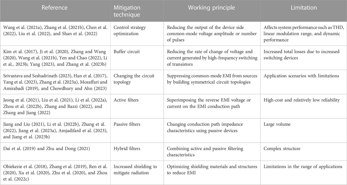
TABLE 2. Summary of EMI mitigation techniques for power electronic equipment.
4.2 Mitigation of interference sources
In power electronic equipment, since the semiconductor switching device will switch between the two states of turn-on and turn-off at high frequency with switching cycles, this is the main source of EMI in the system. Currently, there are three main methods to suppress the source of interference as follows:
4.2.1 Control strategy optimization to mitigate interference sources
Typically, improved modulation strategies are used to reduce EMI noise at the expense of system performance such as total harmonic distortion, linear modulation range, and dynamic performance. For a typical PWM converter, this approach reduces the amplitude or the number of pulses of the common-mode voltage at the output side of the device, thus mitigating EMI generated by the power electronic conversion at the source. MMC is widely used due to its excellent performance. Therefore, for MMC, Chen et al. (2022); Liu et al. (2022); and Shan et al. (2022) further investigated the mitigation of EMI in MMC from the perspective of control strategy optimization. Furthermore, especially for low-frequency MMC EMI, improving modulation strategies is more applicable, and Wang et al. (2022) summarized the low EMI modulation methods reducing the low-frequency MMC EMI. So this article will not be repeated. To address the harmful DM and CM EMI generated during the operation of motor drive systems, the integrated EMI filter scheme for paralleled inverters using the zero-CM PWM algorithm is proposed by Zhang et al. (2021). In addition, Wang et al. (2021) presented a variable switching frequency pulse width modulation method for the three-phase current source inverters (CSIs) used to suppress harmonics induced by the switching process of active components such as IGBT.
4.2.2 Reducing the rate of change of voltage and current generated by the high-frequency switching of transistors
One way to avoid the rate of change of voltage and current is to reduce the number of submodules that are inserted or bypassed simultaneously for MMC (Wang et al., 2022). A novel voltage balancing control method is proposed for du/dt reduction, with only two submodules switching their modes in a control cycle when the voltage sorting changes (Ji et al., 2020). Moreover, it has been shown that proper buffer circuits can not only suppress the voltage spikes generated by the switching process but also reduce device losses and EM interference (Kim et al., 2017; Zhang et al., 2023a). Although buffer circuits are easy to implement, this scheme must sacrifice a certain amount of efficiency to reduce EMI (Zhang and Wang, 2020). In addition, zero voltage switching (ZVS) control is an effective and promising method to improve the power density, efficiency, and EMI of two-coupled inverters (Wang et al., 2021; Yen and Chao, 2022; Li et al., 2023; Yang, 2023). However, this circuit increases the number of devices while introducing auxiliary switches, which increase the number of switches, and the total loss and applicability are insufficient. A variable switching frequency PWM (VSFPWM) for the full-range ZVS control is proposed by Li et al. (2023), as shown in Figure 5. The proposed VSFPWM shows a good performance of ZVS realization in various load situations and a good dynamic response of the inverter during the current step change.
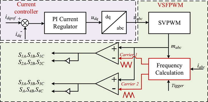
FIGURE 5. VSFPWM block diagram.
4.2.3 Changing the circuit topology
Based on the traditional power electronic converter, due to the asymmetry of its circuit structure, no matter what kind of modulation method is adopted, it is impossible to completely eliminate the CM interference source from the source. For this reason, many scholars start from the topology to achieve the goal of suppressing the common mode electromagnetic interference from the source of the interference. Han et al. (2017) proposed a balanced inverter topology with a third power switch added to each inverter bridge arm to achieve the purpose of balancing the common-mode voltage generated by the bridge arms. The advantage of this scheme is that the modulation and control strategy of a conventional inverter can be followed and only three power switches need to be added. Srivastava and Seshadrinath (2023) presented a new grid-connected transformer-less inverter based on a seven-level common ground (CG) switched capacitor (SC) with triple boost capability of the input voltage. Therefore, this inverter is more suitable for low-voltage PV applications without any boost conversion stage. The CG configuration of this inverter helps bypass stray capacitance, thereby eliminating leakage currents and thus significantly reducing EMI. However, changing the circuit topology is generally complex since the trade-offs between efficiency, cost, and EMI level need to be considered. Changes in circuit topology may improve EMI performance but could potentially lead to reduced efficiency due to increased switching losses or other factors (Yang et al., 2023; Zhang et al., 2023b; Mozaffari and Amirabadi, 2019; Chowdhury and Ahn, 2023). In addition, altering the circuit topology can impact the cost of components, manufacturing, and testing. Some literature studies suppresses EMI by adding power switches to construct symmetrical topology or using the complicated package structure, resulting in increased costs (Han et al., 2017; Zhang et al., 2023a). Nevertheless, under certain circumstances, the efficiency, cost, and EMI level can be balanced. Mozaffari and Amirabadi (2019) proposed a new class of topologies of single-stage high-frequency AC-link power converters, which features a significantly reduced link peak current, reduced switch ratings, and reduced total number of power switches. These features enhance the efficiency, reduce the total cost, and increase the power density of the system. However, the modulation method and the design of the filter circuit also influenced the efficiency, cost, and EMI level (Lee and Lai, 2021; Li et al., 2023). Herein, it is also necessary to be studied in depth in the future.
4.3 Optimization of the impedance characteristics of conduction paths
The principle of changing the impedance characteristics of the conduction path is to reduce the total EMI noise at the measurement end by introducing active or passive networks in the conduction path. These networks are known as EMI filters. Therefore, comparing with other overviews, this paper focuses on reviewing the EMI filters reducing EMI along EMI conduction paths. EMI filters can broadly be classified into passive filters, active filters, and hybrid active filters.
4.3.1 Active filters
The first active filter was proposed by Zhang and Jiang (2022), and the basic idea is to mitigate noise by superimposing a reverse EMI voltage or current on the EMI conduction path. The basic circuit topology of the active filter is shown in Figure 6. Active filters have excellent filtering effects, compactness, and power density that can be realized in power converters, higher costs due to the need for additional switching devices, and lower reliability compared to passive filters. A transformer-less AEF, sprung from the concept of virtual impedance enhancement is proposed (Zhang and Bazzi, 2022). The proposed design features feedforward control with current-sensing-voltage-compensating. Experimental results with an AC–DC power converter and a DC–AC inverter show that the proposed AEF can generally be applied to reduce conducted EMI on either AC or DC power lines. The method of combining chaotic pulse width modulation (CPWM) with the AEF design was proposed to enhance the EMI high-frequency mitigation effect (Li et al., 2022a). The simulation and experimental results show that the desired amplified gain of AEF can be reduced by CPWM, and thus, the EMI high-frequency inhibitory effect will be enhanced. No extra costs are needed for this optimization method, which is suitable for high-power density power electronics devices, and the high-frequency EMI mitigation of AEF is effectively improved. CM currents are one of the main causes of EMI generation, and many articles have optimized active filters in terms of attenuating CM noise (Liu et al., 2021; Zhou et al., 2022; Zhang and Jiang, 2022). The letter proposed a new configuration of a neutral point-based common-mode active electromagnetic interference filter (NP-CM-AEF). It is achieved by setting the reference of the filtering system to the neutral point of equipment under tests (Zhou et al., 2022). Jeong et al. (2021) proposed an AEF realized by a customized integrated circuit (IC) to reduce conducted emission noises. A fully transformer-isolated feedforward current-sense current-compensation structure is selected as a base topology of AEF. To achieve the high reliability of the proposed AEF using low-voltage IC devices, the injection transformer is added to protect IC devices from high-voltage hazards.
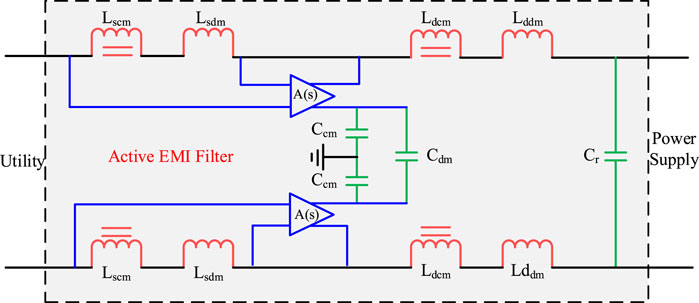
FIGURE 6. Schematic circuit diagram of an active filter.
4.3.2 Passive filters
Passive filters are a combination of series inductors and shunt capacitors, i.e., LC filters form passive filters (Amjadifard et al., 2023). The basic circuit topology of the passive filter is shown in Figure 7. In recent years of research, passive filters are widely used in the industry because of their higher reliability than active filters. However, PEFs bring additional volume, weight, and cost for power converters, especially CM inductors in PEFs, and it is a tricky issue for the high-power-density converters that must meet the electromagnetic compatibility specification. In order to design compact PEFs for power converters with PWM, a volume reduction method of CM inductors with chaotic PWM is proposed (Li et al., 2022b). Wang et al. (2023) proposed a new method of integrating the DC and AC CM inductors through magnetic coupling to reduce the volume of PEF. Some scholars have proposed an unbalanced Wheatstone bridge and a two-stage notch filter to attenuate the increased CM and DM noise, respectively. The unbalanced Wheatstone bridge with a single-stage LC filter proposed in the paper reduces the total CM inductance in order to thereby solve the problem of excessive size. The two-stage trap filter proposed in the article aimed to achieve high attenuation, solved the problem of its parameter variation, and helped reduce the size and weight of the DM filter (Zhang et al., 2022). Jiang and Liu (2021) stated that a modified LCL-LC harmonic filter is structured to strengthen its EMI suppression ability. Considering the common-mode and differential-mode EMI propagation paths, the traditional LCL-LC filter is split into a symmetrical topology, with the midpoint of the split filtering capacitors connected to the midpoint of the DC-link capacitor. In addition, with the development of the emerging flexible multilayer foil (FMLF) technology, integrating all CM and differential-mode DM filter elements in the same unit with a more compact design can effectively reduce the volume of the filter (Jiang et al., 2023; Jiang et al., 2023).
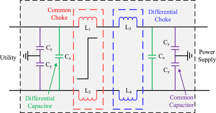
FIGURE 7. Schematic circuit diagram of the passive EMI filter.
4.3.3 Hybrid filters
Hybrid filters are a combination of passive and active filters. Hybrid EMI filters reduced noise over a wide bandwidth. A hybrid EMI filter reduces the noise over a wide bandwidth (Dai et al., 2019; Zhu and Dong, 2021).
4.4 Increased shielding to mitigate radiation
The shielding method is more suitable for crosstalk and other problems that exist in the coupling path of electromagnetic interference in the power supply system. Shielding optimization methods are mainly for the design of different structures of shielded cables and shielded panels to analyze and improve the noise reduction effect. The first type of the shielding optimization method is to optimize the selection of materials, such as the use of shielded cables instead of ordinary cables (Xu et al., 2020; Zhou et al., 2022); the second type of the shielding optimization method is to optimize the shielding structure through simulation, such as optimizing the feeder conductor cross section (Obiekezie et al., 2018), or the use of finite element analysis to determine the shielding material, the optimal thickness, and the aperture size so that the shielding effect is maximized. Some shielding methods are also applicable to MMC. There have been reviews describing in detail the main shielding methods involved in the MMC-HVDC station including four categories (Wang et al., 2022): submodule case, shielding ring of the value tower (Zhu et al., 2020), cable shielding (Ren et al., 2020), and shielding wall of the whole station (Zhang et al., 2019). However, it is worth noting that, at this stage, for power electronic equipment, the disturbed body usually adopts the receiver, making the study of electromagnetic interference to mainly focus on the interference source and conduction path.
5 Conclusion
This paper presents a comprehensive review of EMI in modern power electronic converters, recognizing the inevitable challenges associated with the widespread adoption of modern power electronic devices. The paper categorizes EMI into two distinct types, namely, conducted EMI and radiated EMI, delineating their propagation characteristics, modeling methodologies, measurement techniques, and EMI mitigation techniques. Consequently, it unveils pressing issues that warrant immediate attention and outlines potential directions for the evolution of electromagnetic compatibility in modern power electronic converters as follows:
(1) Modeling challenges: Modeling predictions pose a significant challenge due to the diverse nature of the two EMI interference mechanisms. Conducted EMI is influenced by topology optimization, control strategies, device characteristics, and package design, with prediction accuracy hinging on the precision of modeling. In contrast, radiated EMI modeling heavily relies on antenna theory and fundamental electromagnetic field theory. At present, the majority of EMI research focuses on scenario-specific analyses and mitigation techniques tailored to inverters, which exhibit certain limitations. This paper synthesizes the methodologies for EMI analysis and modeling, offering a comprehensive repository of research on EMI characteristics in modern power electronic-based applications. This compilation aids in deepening the understanding of EMI within converters.
(2) Modulation strategy trade-offs: Current studies reveal that while modulation strategies can effectively reduce interference source noise, they often introduce trade-offs impacting the system output waveform quality and are susceptible to the dead zone effect. Therefore, on the basis of not sacrificing the voltage utilization rate and output current harmonic characteristics, it is of great significance to propose a modulation strategy that can efficiently eliminate the influence of the dead zone effect, in order to break through the bottleneck of the existing technology of EMI modulation and mitigation techniques, and to improve its EMI mitigation performance.
(3) EMI filter challenges: In the realm of conducted EMI above the MHz level, the inherent limitations to active EMI filters necessitate the use of passive EMI filters. However, the efficacy of passive EMI filters can be compromised by spurious parameters, making it challenging to meet EMC standards for converter EMI emissions in high-frequency bands above the MHz range. Thus, the proposition of passive EMI mitigation techniques boasting excellent high-frequency suppression capabilities, minimal design complexity, and high flexibility becomes imperative. Such a strategy is instrumental in compensating for the influence of spurious parameters on the high-frequency performance of passive EMI filters, offering practical engineering applications that facilitate efficient converter-conducted EMI mitigation across the entire frequency spectrum.
In summary, this paper not only provides a comprehensive understanding of EMI challenges in modern power electronic converters but also outlines crucial directions for future research and technological advancements in the realm of electromagnetic interference.
Author contributions
LY: Conceptualization, Writing–review and editing. JZ: Conceptualization, Writing–review and editing. ZL: Visualization, Writing–original draft. MH: Writing–original draft. GC: Resources, Writing–review and editing. WL: Supervision, Writing–review and editing.
Funding
The author(s) declare that their financial support was received for the research, authorship, and/or publication of this article. This work was supported in part by the National Natural Science Foundation of China under grant no. 52307156 and the Changsha Natural Science Foundation under grant no. kq2208279.
Conflict of interest
Authors GC and WL were employed by the Jiangsu Power Transmission and Transformation Co., Ltd.
The remaining authors declare that the research was conducted in the absence of any commercial or financial relationships that could be construed as a potential conflict of interest.
Publisher’s note
All claims expressed in this article are solely those of the authors and do not necessarily represent those of their affiliated organizations, or those of the publisher, the editors, and the reviewers. Any product that may be evaluated in this article, or claim that may be made by its manufacturer, is not guaranteed or endorsed by the publisher.
References
American national standard for methods of measurement (2009). American national standard for methods of measurement of radio-noise emissions from low-voltage electical and electronic equipment in the range of 9 kHz to 40GHz. doi:10.1109/IEEESTD.2017.8066479
Amjadifard, R., Bina, M. T., Khaloozadeh, H., Bagheroskouei, F., and Shahirinia, A. (2023). Suggesting a non-unity turn ratio two-winding coupled inductor for filtering CM EMI noise in an SRC. IEEE Trans. Consumer Electron. 69 (3), 458–466. doi:10.1109/tce.2023.3287982
Avinash, , and Gupta, N. (2023). “Low-cost electromagnetic absorbers for shield packaging,” in IEEE Transactions on Components, Packaging and Manufacturing Technology 13 (3), 374–381. doi:10.1109/TCPMT.2023.3265706
Cao, Y., Fan, B., Bai, Y., Mitrovic, V., Dong, D., Burgos, R., et al. (2023). Common-mode noise reduction and capacitor voltage auto-balance using bridged midpoints and coupled inductor in a 3-L buck-boost converter. IEEE Trans. Power Electron. 38 (10), 12365–12369. doi:10.1109/tpel.2023.3296335
Chen, J., Yang, J., Yang, S., Ho, S. L., and Ren, Z. (2018). A 2-D nonlinear ambipolar diffusion equation model of an IGBT and its numerical solution methodology. IEEE Trans. Magnetics 54 (3), 1–4. doi:10.1109/tmag.2017.2771339
Chen, X., Chen, W., Yang, X., Ren, Y., and Qiao, L. (2021). Common-mode EMI mathematical modeling based on inductive coupling theory in a power module with parallel-connected SiC MOSFETs. IEEE Trans. Power Electron. 36 (6), 6644–6661. doi:10.1109/tpel.2020.3046658
Chen, J., Jiang, D., Sun, W., and Pei, X. (2022). Common-mode voltage reduction scheme for MMC with low switching frequency in AC–DC power conversion system. IEEE Trans. Industrial Inf. 18 (1), 278–287. doi:10.1109/tii.2021.3075224
Chowdhury, S. A., and Ahn, D. (2023). “Self-tuning LCC receiver for improved efficiency and EMI mitigation in spread-spectrum wireless power transfer,” in 2023 IEEE Wireless Power Technology Conference and Expo (WPTCE), 1–5.
Dai, L., Chen, W., Yang, X., Zheng, M., Yang, Y., and Wang, R. (2019). A multi-function common mode choke based on active CM EMI filters for AC/DC power converters. IEEE Access 7, 43534–43546. doi:10.1109/access.2019.2904951
Fan, L., Liu, Z., Liang, Y., Li, H., Rao, B., Yin, S., et al. (2023). Analysis and utilization of common-mode voltage in inverters for power supply. IEEE Trans. Power Electron. 38 (7), 8811–8824. doi:10.1109/tpel.2023.3267974
Gahfif, A., Levy, P. É., Ali, M., Berkani, M., and Costa, F. (2019). “EMC “Black Box” model for unbalanced power electronic converters,” in 2019 International Symposium on Electromagnetic Compatibility - EMC EUROPE, Barcelona, Spain, 2-6 September 2019, 957–962.
Haider, M., Baev, A., Kuznetsov, Y., and Russer, J. A. (2018). “Near-field to far-field propagation of correlation information for noisy electromagnetic fields,” in 2018 48th European Microwave Conference (EuMC), Madrid, Spain, 23-27 September 2018, 1190–1193.
Han, D., Morris, C. T., and Sarlioglu, B. (2017). Common-mode voltage cancellation in PWM motor drives with balanced inverter topology. IEEE Trans. Industrial Electron. 64 (4), 2683–2688. doi:10.1109/tie.2016.2633234
Helton, J. C., Lemmon, A. N., and Brovont, A. D. (2023). Comprehensive analysis of filter inductor topology on common-mode conducted emissions for the boost converter. IEEE Trans. Power Electron. 38 (4), 4647–4657. doi:10.1109/tpel.2022.3225756
Hillenbrand, P., Beltle, M., Tenbohlen, S., and Mönch, S. (2017). “Sensitivity analysis of behavioral MOSFET models in transient EMC simulation,” in 2017 International Symposium on Electromagnetic Compatibility-EMC EUROPE, Angers, France, September 4-8, 2017 (IEEE), 1–6.
Hosseinipour, M., Soorki, M. N., and Ahmadian, M. (2018). On effective electromagnetic shielding of modern pulse width modulating adjustable speed drives. IEEE Trans. Electromagn. Compat. 60 (4), 875–884. doi:10.1109/temc.2017.2738840
IEEE Recommended Practice for Antenna Measurements (2022). IEEE recommended Practice for antenna measurements. doi:10.1109/IEEESTD.2022.9714428
IEEE Recommended Practice for Near-Field Antenna Measurements (2012). IEEE recommended Practice for near-field antenna measurements.
IEEE Standard for Power Line Communication (2011). IEEE standard for power line communication equipment--electromagnetic compatibility (EMC) requirements--testing and measurement methods. doi:10.1109/IEEESTD.2011.5682873
IEEE Std (2013). IEEE standard for calibration of electromagnetic field sensors and probes (excluding antennas) from 9 kHz to 40 GHz, 1–111. IEEE Std 1309-2013 (Revision of IEEE Std 1309-2005). doi:10.1109/IEEESTD.2013.6673999
International Electrotechnical Commission (2014). Specification for radio disturbance and immunity measuring apparatus and methods.
IrishStandard (2006). Industrial, scientific and medical equipment-Radio-frequency disturbance characteristics-Limits and methods of measurement.
Jeong, S., Park, J., and Kim, J. (2021). A customized integrated circuit for active EMI filter with high reliability and scalability. IEEE Trans. Power Electron. 36 (11), 12631–12645. (in English). doi:10.1109/tpel.2021.3083286
Ji, S., Zhang, L., Huang, X., Palmer, J., Wang, F., and Tolbert, L. M. (2020). A novel voltage balancing control with dv/dt reduction for 10-kV SiC MOSFET-based medium voltage modular multilevel converter. IEEE Trans. Power Electron. 35 (11), 12533–12543. doi:10.1109/tpel.2020.2987962
Jia, N., Tian, X., Xue, L., Bai, H., Tolbert, L. M., and Cui, H. (2022). “In-package common-mode filter for GaN power module with improved radiated EMI performance,” in 2022 IEEE Applied Power Electronics Conference and Exposition (APEC), 974–979.
Jiang, S., and Liu, Y. (2021). EMI noise reduction for the single-phase grid-connected inverter with A modified harmonic filter design. IEEE Trans. Electromagn. Compat. 63 (3), 739–751. doi:10.1109/temc.2020.3039243
Jiang, D., Chen, J., and Shen, Z. (2019). Common mode EMI reduction through PWM methods for three-phase motor controller. CES Trans. Electr. Mach. Syst. 3 (2), 133–142. doi:10.30941/cestems.2019.00019
Jiang, S., Wang, P., Wang, W., and Xu, D. (2023a). Modeling and design of full electromagnetic integration of a symmetrical EMI filtering circuit with flexible multi-layer foil technique. IEEE Trans. Electromagn. Compat. 65 (2), 414–424. doi:10.1109/temc.2022.3224299
Jiang, S. Q., Wang, P. B., Wang, W., Liu, Y. T., and Xu, D. G. (2023b). Full electromagnetic integration of impedance-balanced EMI filters for single-phase power converters. IEEE Trans. Power Electron. 38 (6), 7166–7182. (in English). doi:10.1109/tpel.2023.3246177
Joint Working Group CIGRE (2009). Guide for measurement of radio frequency interference form HV and MV substations, Document CIGRE391. Joint Working Group CIGRE/CIRED C4.
Kharanaq, F. A., Emadi, A., and Bilgin, B. (2020). Modeling of conducted emissions for EMI analysis of power converters: state-of-the-art review. IEEE Access 8, 189313–189325. doi:10.1109/access.2020.3031693
Kim, T., Feng, D., Jang, M., and Agelidis, V. G. (2017). Common mode noise analysis for cascaded boost converter with silicon carbide devices. IEEE Trans. Power Electron. 32 (3), 1917–1926. doi:10.1109/tpel.2016.2569424
Kumaresan, H. A., Ewe, H. T., Vetharatnam, G., and Jiang, L. J. (2021). “Model computation with second-order radiative transfer equation for snow medium using coupled finite element method and method of moment and relaxed hierarchical equivalent source algorithm,” in 2021 IEEE International Geoscience and Remote Sensing Symposium IGARSS, Brussels, Belgium, 11-16 July 2021, 1417–1420.
Lai, Y., Wang, S., Yang, Y., Huang, Q., and Ma, Z. (2023). “Review on modeling and emissions from EMI filters in power electronics: inductors,” in 2023 IEEE Symposium on Electromagnetic Compatibility and Signal/Power Integrity (EMC+SIPI), Grand Rapids, Michigan, 28th July- 4th August 2023, 566–572.
Lee, M., and Lai, J. S. (2021). Spread-spectrum frequency modulation with adaptive three-level current scheme to improve EMI and efficiency of three-level boost DCM PFC. IEEE Trans. Power Electron. 36 (3), 2476–2480. doi:10.1109/tpel.2020.3016238
Li, Y., Zhang, H., Wang, S., Sheng, H., Chng, C. P., and Lakshmikanthan, S. (2018). Investigating switching transformers for common mode EMI reduction to remove common mode EMI filters and Y-capacitors in flyback converters. IEEE J. Emerg. Sel. Top. Power Electron. 6 (4), 2287–2301. doi:10.1109/jestpe.2018.2827041
Li, H., Wang, S., Zhang, C., and Wang, Z. (2022a). “A compact passive-active hybrid EMI filter with phase compensation for power converters,” in 2022 4th International Conference on Smart Power and Internet Energy Systems (SPIES), Beijing, China, 510–516. doi:10.1109/SPIES55999.2022.10081963
Li, H., Ding, Y. H., Zhang, C. M., Yang, Z. C., Yang, Z. C., and Zhang, B. (2022b). A compact EMI filter design by reducing the common-mode inductance with chaotic PWM technique. IEEE Trans. Power Electron. 37 (1), 473–484. (in English). doi:10.1109/tpel.2021.3100360
Li, X., Sun, Y., Jiang, L., Wang, H., Liu, Y., and Su, M. (2023a). Common-mode circuit analysis of current-source photovoltaic inverter for leakage current and EMI. IEEE Trans. Power Electron. 38 (6), 7156–7165. doi:10.1109/tpel.2023.3241205
Li, Q., Ma, Y., Zhao, X., Jiang, D., and Zhang, Y. (2023b). VSFPWM based on circulating current ripple prediction for ZVS in two paralleled grid-tied inverters with coupled inductors. IEEE Trans. Industrial Electron. 70 (1), 39–51. doi:10.1109/tie.2022.3146519
Li, J. (2019). Research on the test method of electromagnetic compatibility conduction characteristics of power electronic devices. TianJin: Tianjin University of Technology.
Liu, J., Jiang, D., Sun, W., Zhang, Y., and Chen, J. (2021). “A common-mode active EMI filter design for modular multilevel converters,” in 2021 IEEE 1st International Power Electronics and Application Symposium (PEAS), 1–5.
Liu, H., Chen, J., Jiang, D., Li, H., Pei, X., and Sun, W. (2022). Uniform distribution spread-spectrum modulation strategy for MMC to reduce conducted EMI and switching loss. Chin. J. Electr. Eng. 8 (4), 39–51. doi:10.23919/cjee.2022.000037
Ma, Z., Wang, S., Sheng, H., and Lakshmikanthan, S. (2022a). “Modeling and reduction of radiated EMI due to ground impedance in a high-density active-clamp flyback power adapter,” in 2022 IEEE Applied Power Electronics Conference and Exposition (APEC), Houston, Texas, March 20-25, 2022, 292–299.
Ma, Z., Yang, Y., Yao, J., Wang, S., Sheng, H., Jia, L., et al. (2022b). “Radiated EMI prediction in power converters with power cables based on cable antenna voltage gain extraction,” in 2022 IEEE International Symposium on Electromagnetic Compatibility and Signal/Power Integrity (EMCSI), Spokane, WA, United States, 1 - 5 August 2022, 510–515. doi:10.1109/EMCSI39492.2022.9889677
Ma, Z., Lai, Y., Yang, Y., Huang, Q., and Wang, S. (2023a). “Review of radiated EMI modeling and mitigation techniques in power electronics systems,” in 2023 IEEE Applied Power Electronics Conference and Exposition (APEC), Houston, TX, USA, 20-24 March 2022, 1776–1783.
Ma, Z., Wang, S., Sheng, H., and Lakshmikanthan, S. (2023b). Modeling, analysis and mitigation of radiated EMI due to PCB ground impedance in a 65 W high-density active-clamp flyback converter. IEEE Trans. Industrial Electron. 70 (12), 12267–12277. doi:10.1109/tie.2023.3239904
Menzi, D., Bortis, D., and Kolar, J. W. (2021). EMI filter design for a three-phase buck–boost Y-inverter VSD with unshielded motor cables considering IEC 61800-3 conducted and radiated emission limits. IEEE Trans. Power Electron. 36 (11), 12919–12937. doi:10.1109/tpel.2021.3075785
Mozaffari, K., and Amirabadi, M. (2019). A highly reliable and efficient class of single-stage high-frequency AC-link converters. IEEE Trans. Power Electron. 34 (9), 8435–8452. doi:10.1109/tpel.2018.2888583
Natarajan, S., Babu, T. S., Balasubramanian, K., Subramaniam, U., and Almakhles, D. J. (2020). A state-of-the-art review on conducted electromagnetic interference in non-isolated DC to DC converters. IEEE Access 8, 2564–2577. doi:10.1109/access.2019.2961954
Negri, S., Spadacini, G., Grassi, F., and Pignari, S. A. (2022). Black-box modeling of EMI filters for frequency and time-domain simulations. IEEE Trans. Electromagn. Compat. 64 (1), 119–128. doi:10.1109/temc.2021.3105735
Niklaus, P. S., Antivachis, M. M., Bortis, D., and Kolar, J. W. (2021). Analysis of the influence of measurement circuit asymmetries on three-phase CM/DM conducted EMI separation. IEEE Trans. Power Electron. 36 (4), 4066–4080. doi:10.1109/tpel.2020.3025122
Obiekezie, C., Santo, R. d. C., Webb, K., and Cosgrave, J. (2018). Optimized parallel feeder for achieving low magnetic fields in an overhead-feeder-type DC rail system. IEEE Trans. Electromagn. Compat. 60 (3), 623–628. doi:10.1109/temc.2017.2749684
Ren, H., Zhong, L., Yang, X., Li, W., Gao, J., Yu, Q., et al. (2020). Electric field distribution based on radial nonuniform conductivity in HVDC XLPE cable insulation. IEEE Trans. Dielectr. Electr. Insulation 27 (1), 121–127. doi:10.1109/tdei.2019.008345
Seifi, Z., Ghorbani, A., and Abdipour, A. (2021). Analysis and experimental study of radiative microwave pulses effects on the nonlinear performance of a low-noise amplifier. IEEE Trans. Plasma Sci. 49 (3), 1105–1114. doi:10.1109/tps.2021.3057613
Shan, Y., Pei, X., Sun, T., Zhang, M., Zhou, P., and Jiang, D. (2022). Space spread-spectrum strategy for MMC to reduce the conducted EMI. IEEE Trans. Industrial Electron. 69 (11), 10807–10818. doi:10.1109/tie.2021.3125656
Srivastava, A., and Seshadrinath, J. (2023). A single-phase seven-level triple boost inverter for grid-connected transformerless PV applications. IEEE Trans. Industrial Electron. 70 (9), 9004–9015. doi:10.1109/tie.2022.3215815
Sun, J., Li, J., Costinett, D. J., and Tolbert, L. M. (2020). “A GaN-based CRM totem-pole PFC converter with fast dynamic response and noise immunity for a multi-receiver WPT system,” in 2020 IEEE Energy Conversion Congress and Exposition (ECCE), Detroit, Michigan, 11-15 October 2020 (IEEE), 2555–2562.
Sun, T., Pei, X., Shan, Y., Pei, J., and Jiang, D. (2023). Submodule switching-state based EMI modeling and mixed-mode EMI phenomenon in MMC. IEEE Trans. Power Electron. 38 (2), 1831–1843. doi:10.1109/tpel.2022.3214990
Takahashi, K., Ibuchi, T., and Funaki, T. (2017). “Frequency domain simulation of conducted EMI in power electronic converters considering internal near field couplings by FEM,” in 2017 International Symposium on Electromagnetic Compatibility - EMC EUROPE, Angers, France, September 4-8, 2017, 1–6.
Takahashi, A., Nomura, K., Kojima, T., and Nomura, T. (2021). Fabrication and evaluation of a magnetically coupled EMI filter designed with topology optimization. IEEE Trans. Power Electron. 36 (11), 12620–12630. doi:10.1109/tpel.2021.3081121
Thomas, R., Li, F., and Garrett, C. (2000). “Prediction of radiated EMI from high frequency power converters,” in 2000 Eighth International Conference on Power Electronics and Variable Speed Drives (IEE Conf. Publ. No. 475), London, UK, 18-19 September 2000, 80–85.
Vrankovic, Z., Sizov, G., Skibinski, G. L., Suryadevara, R., and Da, Y. (2022). “Analysis, design and PCB optimization of a DC bus planar CM inductor to reduce EMI in SiC converters,” in 2022 IEEE Energy Conversion Congress and Exposition (ECCE), Detroit, Michigan, October 9 – October 13, 2022, 1–8.
Wan, L., Wu, X., Liu, X., Grassi, F., Spadacini, G., and Pignari, S. A. (2023). “A flexible black-box model for conducted emission predictions with different switching frequencies,” in 2023 IEEE Symposium on Electromagnetic Compatibility and Signal/Power Integrity (EMC+SIPI), Grand Rapids, Michigan, July- 4 August 2023, 1–6.
Wang, R., Liu, K., and Jiang, D. (2021a). “A VSFPWM method of three-phase CSI for EMI mitigation based on DC current ripple prediction,” in 2021 IEEE International Joint EMC/SI/PI and EMC Europe Symposium, 83–88.
Wang, Z., Xu, Y., Liu, P., Zhang, Y., and He, J. (2021b). Zero-voltage-switching current source inverter fed PMSM drives with reduced EMI. IEEE Trans. Power Electron. 36 (1), 761–771. doi:10.1109/tpel.2020.3004633
Wang, Z., Li, H., Chu, Z., Zhang, C., Yang, Z., Shao, T., et al. (2022). A review of EMI research in modular multilevel converter for HVDC applications. IEEE Trans. Power Electron. 37 (12), 14482–14498. doi:10.1109/tpel.2022.3179234
Wang, X., Wu, M., Rajagopalan, J., Mohan, A., Kim, D., and Hwang, C. (2023a). Investigation of the radiation mechanism of heatsinks based on characteristic mode theory. IEEE Trans. Electromagn. Compat. 65, 1446–1454. doi:10.1109/temc.2023.3297553
Wang, A., Zheng, F., Gao, T., Wu, Z., and Li, X. (2023b). Integrated CM inductor for both DC and AC noise attenuation in DC-fed motor drive systems. IEEE Trans. Power Electron. 38 (1), 510–522. doi:10.1109/tpel.2022.3205773
Wu, L., Wang, W., Lyu, Z., Zhong, Y., and Liu, J. (2023). Coupling effect on unbalanced voltages and power under faulty condition in triple three-phase wind power generators. IEEE Trans. Industrial Electron. 71 (2), 1308–1318. doi:10.1109/tie.2023.3262881
Xu, M., Wang, Y., Li, X., Dong, X., Zhang, H., Zhao, H., et al. (2020). Analysis of the influence of the structural parameters of aircraft braided-shield cable on shielding effectiveness. IEEE Trans. Electromagn. Compat. 62 (4), 1028–1036. doi:10.1109/temc.2019.2926393
Xu, C., Zhang, F., and Dong, G. (2021). “Wideband modeling of transformer common-mode characteristics using RLC ladder network,” in 2021 IEEE 1st International Power Electronics and Application Symposium (PEAS), Shanghai, China, November 12-15, 2021, 1–6.
Yang, Q., Wang, L., Qi, Z., Lu, X., Ma, Z., Yang, F., et al. (2023). Analysis and optimization of high-frequency switching oscillation conducted CM current considering parasitic parameters based on a half-bridge power module. IEEE Trans. Power Electron. 38 (10), 12659–12674. doi:10.1109/tpel.2023.3291893
Yang, Y. (2023). A passive augmented circuit for EMI reductions of full-bridge inverters with conventional phase shift control in wireless power transfer systems. IEEE Trans. Power Electron. 38 (11), 13286–13297. doi:10.1109/tpel.2023.3300915
Yao, J., Wang, S., and Luo, Z. (2022). Modeling, analysis, and reduction of radiated EMI due to the voltage across input and output cables in an automotive non-isolated power converter. IEEE Trans. Power Electron. 37 (5), 5455–5465. doi:10.1109/tpel.2021.3128628
Yen, W. W., and Chao, P. C. P. (2022). A ZVS phase-shift full-bridge converter with input current steering to reduce EMI noise. IEEE Trans. Power Electron. 37 (10), 11937–11950. doi:10.1109/tpel.2022.3170234
Yoshida, S., Yasuzumi, T., Tanaka, T., and Fujiwara, Y. (2023). “Package design consideration for suppressing radiated EMI noise in semi-bridgeless PFC converters,” in 2023 35th International Symposium on Power Semiconductor Devices and ICs (ISPSD), 56–59.
Zhang, Z., and Bazzi, A. M. (2022). A virtual impedance enhancement based transformer-less active EMI filter for conducted EMI suppression in power converters. IEEE Trans. Power Electron. 37 (10), 11962–11973. (in English). doi:10.1109/tpel.2022.3172388
Zhang, Y., and Jiang, D. (2022). “An active EMI filter in grounding circuit for DC side CM EMI suppression in motor drive system,” in IEEE Transactions on Power Electronics 37 (3), 2983–2992. doi:10.1088/0143-0807/27/4/007
Zhang, B., and Wang, S. (2020). A survey of EMI research in power electronics systems with wide-bandgap semiconductor devices. IEEE J. Emerg. Sel. Top. Power Electron. 8 (1), 626–643. doi:10.1109/jestpe.2019.2953730
Zhang, Y., and Wang, S. (2022). “Characterization and design of filter inductors and capacitors to suppress the radiated EMI in A power converter,” in 2022 International Power Electronics Conference (IPEC-Himeji 2022- ECCE Asia), Himeji, Japan, 15-19 May 2022, 1082–1089.
Zhang, H., Yang, L., Wang, S., and Puukko, J. (2017a). Common-mode EMI noise modeling and reduction with balance technique for three-level neutral point clamped topology. IEEE Trans. Industrial Electron. 64 (9), 7563–7573. doi:10.1109/tie.2017.2677344
Zhang, H., Wang, S., Li, Y., Wang, Q., and Fu, D. (2017b). Two-capacitor transformer winding capacitance models for common-mode EMI noise analysis in isolated DC–DC converters. IEEE Trans. Power Electron. 32 (11), 8458–8469. doi:10.1109/tpel.2017.2650952
Zhang, J., Lu, T., Zhang, W., Xu, J., and Li, W. (2019). Measurement and analysis of radiated disturbance characteristics of ±320 kV modular multilevel converter system. IEEE Access 7, 10028–10036. doi:10.1109/access.2019.2891339
Zhang, Z., Hu, Y., Chen, X., Jewell, G. W., and Li, H. (2021a). A review on conductive common-mode EMI suppression methods in inverter fed motor drives. IEEE Access 9, 18345–18360. doi:10.1109/access.2021.3054514
Zhang, Y., Shen, Z., and Jiang, D. (2021b). An integrated EMI filter scheme for paralleled inverter with zero-CM PWM algorithm. IEEE J. Emerg. Sel. Top. Power Electron. 9 (1), 716–726. doi:10.1109/jestpe.2019.2962918
Zhang, Y., Li, H., and Shi, Y. (2022). Electromagnetic interference filter design for a 100 kW silicon carbide photovoltaic inverter without switching harmonics filter. IEEE Trans. Industrial Electron. 69 (7), 6925–6934. doi:10.1109/tie.2021.3095806
Zhang, H., Wu, Y., Li, H., Yin, S., Jin, S., Lin, S., et al. (2023a). Design and evaluation of a 1200-V/200-A SiC three-level NPC power module. IEEE Trans. Industry Appl. 59 (5), 6412–6426. doi:10.1109/tia.2023.3288500
Zhang, Y., Xie, Y., Chen, C., Guo, X., Yan, Y., Yang, L., et al. (2023b). Comprehensive analysis and optimization of parasitic capacitance on conducted EMI and switching losses in hybrid-packaged SiC power modules. IEEE Trans. Power Electron. 38 (11), 13988–14003. doi:10.1109/tpel.2023.3306892
Zhou, Y., Chen, W., Yang, X., Zhang, R., Yan, R., Liu, J., et al. (2022a). A new integrated active EMI filter topology with both CM noise and DM noise attenuation. IEEE Trans. Power Electron. 37 (5), 5466–5478. doi:10.1109/tpel.2021.3130113
Zhou, Y. X., Chen, W., Yang, X., Yu, Z., Meng, X., Ren, P., et al. (2022b). A novel neutral point-based active EMI filter for common mode noise attenuation. IEEE Trans. Power Electron. 37 (9), 10081–10085. (in English). doi:10.1109/tpel.2022.3161288
Zhou, M., Guo, Y., Zhao, W., Cai, L., Wang, J., and Yang, T. (2022c). Comparison of shielding effectiveness of different shielding methods for multi-core cable on lightning surge current. IEEE Trans. Electromagn. Compat. 64 (5), 1742–1749. doi:10.1109/temc.2022.3200400
Zhu, Y., and Dong, Y. (2021). A novel compact wide-stopband filter with hybrid structure by combining SIW and microstrip technologies. IEEE Microw. Wirel. Components Lett. 31 (7), 841–844. doi:10.1109/lmwc.2021.3078897
Zhu, R., Lin, N., Dinavahi, V., and Liang, G. (2020). An accurate and fast method for conducted EMI modeling and simulation of MMC-based HVdc converter station. IEEE Trans. Power Electron. 35 (5), 4689–4702. doi:10.1109/tpel.2019.2945931
Keywords: electromagnetic interference, electromagnetic compatibility, power electronics, conducted EMI, radiated EMI
Citation: Yuan L, Zhang J, Liang Z, Hu M, Chen G and Lu W (2023) EMI challenges in modern power electronic-based converters: recent advances and mitigation techniques. Front. Electron. 4:1274258. doi: 10.3389/felec.2023.1274258
Received: 08 August 2023; Accepted: 24 October 2023;
Published: 09 November 2023.
Edited by:
Terence O’Donnell, University College Dublin, IrelandCopyright © 2023 Yuan, Zhang, Liang, Hu, Chen and Lu. This is an open-access article distributed under the terms of the Creative Commons Attribution License (CC BY). The use, distribution or reproduction in other forums is permitted, provided the original author(s) and the copyright owner(s) are credited and that the original publication in this journal is cited, in accordance with accepted academic practice. No use, distribution or reproduction is permitted which does not comply with these terms.
*Correspondence: Jian Zhang, emhhbmdqaWFuNTE4NkAxMjYuY29t