 Christian Katlein
 Matthieu Labaste2
 Mario Hoppmann
- 1Alfred-Wegener-Institut Helmholtz-Zentrum für Polar- und Meeresforschung, Bremerhaven, Germany
- 2LOCEAN, Sorbonne Université, CNRS, Paris, France
Ice-tethered ocean profiling systems are an essential tool for the year-round observation of physical and biogeochemical properties of the Arctic Ocean. Despite being considered expendable equipment due to the challenging logistics, their recovery is attractive mainly due to two factors: If the sensors can be retrieved, this allows for their post calibration, which helps to assess sensor drift and biofouling. In addition, the recovery of such expensive equipment can ease off financial pressure on autonomous ocean observation programs by enabling the reuse of central elements after refurbishment. Here we present a method how such profiling systems can be recovered from sea ice by 3 people in about 4 h, without the on-site availability of a fully-equipped vessel. The presented technique combines rope techniques from mountain rescue applications with lightweight equipment and procedures similar to those used for the deployment of such instruments. We provide a detailed description of the whole process, provide suggestions for potential improvements as well as suggestions toward improved instrument design favoring recoverability of future deployments. We conclude that good preparation and practice of the relevant rope procedures is critical to mission success and that a well-selected range of necessary equipment makes the process much more efficient.
Introduction
Observing water column properties underneath the perennial pack ice of the polar oceans remains a tremendous challenge. The persistent ice cover limits accessibility and hampers observations by standard oceanographic equipment. Ships need to be ice breakers or at least ice strengthened, and depend on the ability to create holes of open water around the ship for the operation of most equipment lowered on a wire. While autonomous measurement platforms, such as moorings (e.g., Schauer et al., 2004; Polyakov et al., 2007; Janout et al., 2016), floats (e.g., Klatt et al., 2007; Wong and Riser, 2011), gliders (e.g., Webster et al., 2014) or other autonomous underwater vehicles (AUV) have been deployed in the sea ice zones (e.g., Wadhams et al., 2006; Williams et al., 2015), the persistent sea ice cover currently inhibits their frequent use in ice-covered oceans.
Thus, ice-tethered ocean profilers, such as the ITP (Krishfield et al., 2008; John et al., 2011), IAOOS (Gascard, 2011; Koenig et al., 2017; Athanase et al., 2019), or the less frequently used POPS (Kikuchi et al., 2007) are the standard tool for vertically profiling, long-term oceanographic observations in the sea ice zones. They are composed of a comparably large buoyant surface unit providing a satellite link and sometimes additional instrumentation of varying complexity, and a profiler package performing the oceanographic observations. These profilers are either driven by motor or a buoyancy engine to climb up and down an isolated steel wire that is tensioned between the surface buoy and a bottom weight. Data is transferred from the profiler to the surface unit using inductive modems. Deployments of these units in typical Arctic sea ice conditions can usually be achieved within 4–6 h by 3–4 people, but due to the large weight and form factor, their deployment mostly requires the assistance of lifting and/or dragging equipment, such as helicopters, cranes, and snowmobiles for transportation to the deployment location.
Similar to most other autonomous sea ice observatories, these ocean-profiling buoys are mostly considered expendable despite their significant cost. Only occasionally the timing of international research expeditions allows an opportunistic recovery of such systems, given they survived the harsh polar conditions, and can still be located. Due to its usually large weight and size, the recovery of the main buoy hull is mostly restricted to situations where a crane is available. As the wire and sometimes the buoy also sit frozen fast into the ice, recovery is very tricky unless an icebreaker can gently break the buoy free from the ice. But even with the capacities of an ice-going research vessel, recovery of the attached profiling system—if still in place—remains a risky operation that, if not performed carefully, can result in the loss of the instrument. The workflow can vary from ship to ship and for different scenarios, but generally resembles the procedures for recovery of oceanographic moorings (Kemp et al., 2005). Recovery of the profiling instruments should be of high priority to allow for post-deployment sensor calibrations, especially if equipped with oxygen optodes or bio-optical instrumentation, for which a proper calibration and knowledge of the sensor condition is of particular value (Laney et al., 2014; Johnson et al., 2017). In addition, recovery of the profiling units can account for substantial savings in instrument costs, as the profiler is the main cost factor that can usually be refurbished and re-used. Also, the recovery of profilers with sensor or engineering failures is of high interest to the international research community. Much can be learned from the analysis of a recovered damaged system on how its engineering can be improved for more successful future deployments. This also applies to situations where the communication link to a profiler stops working soon after deployment, and the equipment needs to be retrieved to avoid the loss of valuable instrumentation. It is also preferable to retrieve both faulty and successful systems after a traverse of the Arctic basin before they will likely get damaged by ground contact with the shelf regions to reduce pollution by hazardous materials, such as the lithium battery packs contained in the units.
To our knowledge, no recovery of an under-ice profiling unit without the use of powered lifting devices and winches has been described in the scientific literature. The objective of this paper is thus to publish a method on how the profiler of an ice-based ocean profiling system of any type can be recovered within a few hours by three trained people. We demonstrate the efficiency of the approach by presenting a case where we recovered a non-functional profiler including a suite of bio-optical sensors without the support of powered lifting devices and with significant logistical and temporal constraints. We hope to herewith enable more recoveries of such profiling units in the future, and provide input for design considerations to increase the recoverability of such systems.
Materials and Techniques
The general idea of this recovery technique is derived from an analogy to similar challenges in mountain rescue operations. The problem of a profiler attached to a several 100 m long steel wire with a ground weight on the order of 50–80 kg is principally equivalent to the rescue of an average person hanging on a rope in a deep glacier crevasse. Similar techniques can be used in both situations, while each scenario obviously comes with individual challenges. In this chapter, we will provide a short overview on the used techniques and equipment.
Friction Knots
In order to be able to lift the wire guiding the profiler, any kind of pulley or winch system needs to be attached to it first. As long as the wire is under tension, one cannot use simple overhand or other knots to connect a shackle or carabiner. Thus, the wire needs to be clamped in a certain way. During deployment of the profiler, it is important that the plastic shielding of the steel wire is not damaged, to avoid corrupting the inductive signal transmission. During recovery, however, the wire is of rather low priority, as it is comparably cheap. In addition, the wire rotates freely in the water column as soon as the tension is released, leading to significant twisting which makes a reuse very inefficient (visible in Figure 1a).
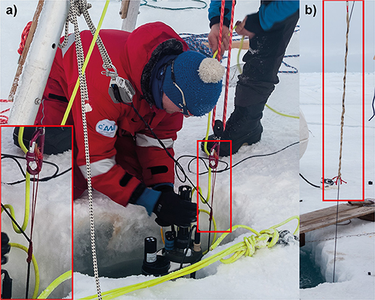
Figure 1. (a) A Klemheist knot holding the weight of the just surfaced profiler and bottom weight. A close up of the Knot is shown in the inlay. Note how the un-tensioned steel wire immediately twists above the knot, making reuse of the wire difficult. (b) A Yale grip partially holding the weight of the system during deployment of a profiler. Both pictures were taken during the training session, where a bigger tripod was used.
Our main way to construct an attachment point on the steel wire is thus by utilizing a “friction knot.” Of the multiple existing friction knots, the Klemheist knot (“Machard” in French, “Kreuzklemmknoten” in German) provides the right characteristics for our application. It provides a quick threading combined with a reliable grip and easy release. To reach a firm grip on the insulated steel wire, the Klemheist knot needs to be threaded with a piece of rope that is significantly thinner than the steel wire. To retain a large enough breaking strength for our application at such small diameters, a cord with Aramid (also known as Kevlar) or ultra-high-molecular-weight polyethylene (UHMWPE also known as Dyneema) core needs to be used (Figure 1a). The Klemheist knot is threaded by first forming a ring from approximately 0.8–1 m of the thin high strength rope using a simple overhand knot. This loop is then neatly wound around the wire at least five times, and finished by threading the knotted end of the ring through the other bight. The number of necessary turns around the wire depends on the combination of rope and wire, but a minimum number of five turns will work in most situations. If the gripping force needs to be increased, this can be achieved by a higher number of turns. Other friction knots might be suitable as well, but the Klemheist provides a good combination of easy threading and release.
A more gentle handling of the wire mantle, e.g., during wire deployment, can be achieved by using a Yale grip (Yale Cordage, Saco, Maine USA) as seen in Figure 1b. While the Yale grip certainly provides a larger breaking strength, puts less strain on the wire mantle and can be released under load, it is much more difficult and time consuming to thread and the necessary installation length makes it unsuitable for work with small tripods such as those suggested in the present method.
Pulley Systems
A pulley system amplifies the force applied by a user. Thus, different pulley systems are an essential tool in every recovery method that does not use any powered lifting devices, such as winches or cranes. A pulley consists of a rope and at least one, or better, several blocks. The force amplification comes with an increase in the length of rope that needs to be pulled out of the pulley to achieve a certain lift. The higher the amplification factor of the pulley system, the more meters of rope need to be pulled out of the system for the same lifting distance. To provide efficient hauling, the amplification must thus be tailored to the task, especially when a load, such as a profiler, needs to be lifted over several 100 vertical meters.
For a more comfortable and safe operation of the heavy system components during the deployment of ocean-profiling buoys, 6:1 rope pulleys with each three parallel blocks on each side are often used. However, 4:1 rope pulleys in a violin layout from sports sailing are easier to operate, with a much reduced likelihood of tangling and still sufficient amplification for most situations. The actual efficiency of a pulley system is highly dependent on the friction losses in the blocks, thus higher theoretical amplifications often do not provide significantly more true lifting capacity.
While two such high amplification pulley systems are used in the initial stage of our recovery method, they are not suitable for the long vertical hauling distances of several 100 m, as the recovery would take too much time. The recovery process is significantly sped up using the simplest 2:1 pulley, also called a “loop haul” or “loose block.” One end of the rope is attached to a fixpoint, while the load is attached in a block which redirects the rope by 180° into the pulling direction. As this pulley system only uses one block, friction losses are small, and 50 m of lift can be generated with only 100 m of working distance. In our recovery technique, we thus use a horizontal 2:1 loop haul. We attach one end of a 50 m long rope to a fixpoint in a distance of 50 m from the recovery hole. A diversion pulley redirected the rope to a wooden bar fixed at the other end of the rope, so the load could easily be lifted by two persons walking away from the deployment hole. While the use of pulling harnesses or belts might provide more comfort, care should be taken that fixing the pulling personal to the rope might be very dangerous in the case of failures in the system. The pulley block was attached to the loaded wire using the Klemheist friction knot. For the 60 kg of bottom weight on the present system, this setup provided safe control over the load and efficient hauling speed. For larger bottom weights, the pulley techniques have to be adjusted accordingly.
Necessary Equipment
While many other components might be suitable for the task, an optimized selection of equipment is necessary especially when recovery is planned by aircraft with limited payload. A complete table of recommended equipment is provided in Table 1.
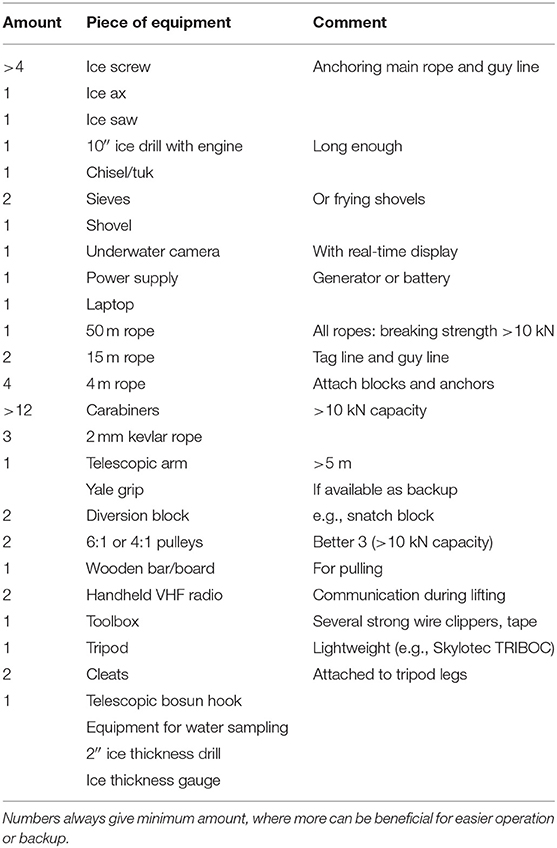
Table 1. Suggested list of equipment for profiler recovery.
Obviously, general equipment for preparing holes in the ice with a diameter >25 cm is necessary. Most importantly a large diameter auger drill with extensions, combined with ice saw, chisel (also known as “Tuk”), ice ax, shovel, and sieves to clear cuttings from holes. A 2″ auger drill should be carried along to determine ice thickness. A number of ice screws is necessary to anchor any ropes to the ice, e.g., to build the main anchor point.
To access the freely hanging wire below the ice, a long telescopic rod of more than 5 m length is required. In an ideal case, the first meter segment can be folded out of the axis, to ease clipping a carabiner to the profiler wire. We used a custom built rod that consisted of 1 m long segments and was originally designed for optical measurements under sea ice, allowing for a tilting of the lowermost segment.
A central piece of the recovery is a lightweight tripod that also fits into a small helicopter, but provides enough strength to handle the forces. We used an aluminum tripod designed for work safety (TRIBOC, Skylotec GmbH, Neuwied, Germany) with a safe working load rating of 500 kg, a working height of 2.45 m with a transport length of 1.75 m at a weight of only 32 kg. Two cleats built for marine applications have to be attached to the tripod legs for operation of the two high amplification (6:1 or 4:1) pulley systems. At least one long rope (e.g., 50 m), two shorter ropes (~15 m) as well as several shorter rope pieces are needed for the entire setup. These ropes should in the best case be low stretch static ropes with a diameter around 10 mm. However, any rope with sufficient breaking strength of at least 10 kN will work. The setup also needs two diversion blocks, plenty of high strength carabiners and several pieces of thin Kevlar or Dyneema cord for the friction knots. For comfortable pulling, we used a 1.5 × 0.05 × 0.05 m wooden plank, but other setups may be used.
Efficient recovery operations are facilitated by monitoring work progress underneath the ice using an underwater camera with real time display. Depending on the system, this requires additional periphery, such as a laptop and power supply. We used a VT 34 PT pan and tilt inspection camera (visatec GmbH, Sulzberg, Germany), a (fully charged) Panasonic Toughbook and a portable lead battery with integrated 220 V output.
For communication between the different teams over the large pulling distance of 100 m, VHF or any other handheld radio device are very useful. In the best case, at least one of these units is prepared for hands-free operation. A general toolbox with several strong wire clippers and tape will be useful, such as a small telescopic gaff.
If time and weight constraints allow, all profiler recoveries will benefit from additional sampling. This could in particular include water sampling from different depths or surface measurements. As this point is easily forgotten in the hectic preparations, we want to stress how important such sampling can be for post calibration of the deployed sensors and thus the scientific value of acquired data.
The Profiler Recovery
In the following paragraphs, we chronologically describe our successful profiler recovery in September 2018 in the Eurasian Basin of the Arctic Ocean. While this is the description of a specific case, methods, and procedures can easily be transferred and applied to any future unsupported manual recovery of ocean profilers of various types.
Deployment Information
The set of buoys revisited during the recovery operation described here was originally deployed on 21 April 2018 in the direct vicinity of the Russian North Pole drifting camp “Barneo” at a position of 89.54° N and 016.78° E. The main buoy site consisted of a IAOOS buoy with a lidar and an ocean profiler with various biogeochemical sensors, an ice mass balance buoy extended with bio-optical sensors, a Snow Buoy, and several other units. The profiling unit was a PROVOR CTS4 (nke Instrumentation, Hennebont, France) equipped with a multispectral light sensor (OCR 500, WetLabs, SeaBird Scientific), nitrate sensor (SUNA V2, Satlantic, SeaBird Scientific), triplet fluorometer (Eco puck, WetLabs, SeaBird Scientific), and oxygen optode (4330F Aandera Data Instruments) in addition to the standard conductivity, temperature, and depth instruments. After deployment, the profiler ceased operations after a while, while the surface part of the buoy remained fully functional. Recovery of the profiler enabled a detailed technical analysis of the failure and reuse of the instrument. All sensors were retrieved in good working condition, indicating that the profiler had likely failed due to either software or buoyancy control issues.
Due to an anomalous drift pattern in the central Arctic during spring and summer 2018 (Moore et al., 2018; Ludwig et al., 2019), the station only moved 170 km away from its initial deployment location during the 5 months of deployment. Simultaneously, the AO18 expedition of the Swedish icebreaker Oden was in the same region between 13 August and 15 September 2018, to perform a 4 weeks drift station close to the geographic North Pole. The selected floe turned out to be only 70 km away from the location of the former Barneo site. As helicopter operations during the time of the drift were limited to a range of 35 km distance from the vessel, recovery could only be attempted during the way back south. However, no dedicated ship time was assigned to the recovery operation, and as the still working surface sensors should not be influenced, the recovery needed to be attempted without any vessel support to avoid a breakup of the ice floe.
Preparations and Floe Location
The profiler recovery was prepared over several days. On the ice floe where icebreaker Oden was moored, we installed a testing setup deploying the same kind of profiler for engineering tests to investigate possible causes for the failure. At the end of the 4 weeks drift, this profiler also had to be retrieved. While shipboard winches and snowmobiles were available on site, we used this opportunity to develop and test the methods necessary for a non-motorized recovery at the Barneo site. This training session allowed us to prove the feasibility of our concept, as well as to test all steps in the process optimizing them for a recovery under time pressure.
The actual recovery was started with a briefing on board Oden and packing of the helicopter on the evening before the operation. Information on the updated positions of the Barneo site was provided by the co-located Snow buoy and received in hourly intervals on board Oden via iridium internet connection.
On 15 September 2018 at 6:33 UTC the Oden helicopter took off, crewed with the three authors and the helicopter pilot. After 10 min of flight, the crew of the helicopter (AS 350 B1, Airbus Helicopters) easily spotted the location of the ice camp and managed to land in the direct vicinity of the deployed buoys (88°04.57′ N, 020°23.5′ E), which provided good visual reference for landing in flat light conditions. After 4 h and 30 min on the ground, the entire recovery operation was finished successfully and the helicopter started back toward icebreaker Oden (landing 11:58 UTC). All retrieved equipment could be carried inside the helicopters cargo and passenger compartments. Transport of retrieved equipment by swing load in a cargo net had been prepared but was not necessary. Air temperatures were around −5°C with almost no winds in the morning, but picking up to 11 m/s at the end of operations.
Work on Site
Upon arrival on the site, first all installations were inspected (Figures 2a,c). After ice thickness was determined to be about 1.5 m around the buoy site, the first 10″ holes were drilled directly next to the buoy. This hole was then widened such that the retrieval of the profiler package could be started.
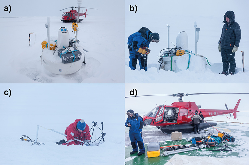
Figure 2. (a) Initial state of surface buoy as found directly after landing. (b) Preparing recovery of the profiler by drilling a hole just next to the buoy. (c) Repairing a Snow Buoy that had been damaged by a polar bear. (d) All recovered equipment including all equipment used for the operation gathered on the helideck after unloading.
In a first step, the tripod was set up directly over the hole and the three legs were connected with a supporting chain to increase the bearing capacity of the tripod. The 6 m long metal pole was assembled in such a way that the lowermost segment was slightly bent inwards to allow easier access to the profiler wire. At the end of the pole we attached a carabiner held open by tape, which was pre-clipped into a loop of rope secured to the surface buoy. In a first attempt, this carabiner was hooked into an element of the chain connecting the profiler wire to the surface wire. However, it turned out that, contrary to design drawings of the buoy, the chain was not long enough to pull it to the surface, so that a deeper clip-in point was needed to proceed with recovery (Figure 3a).
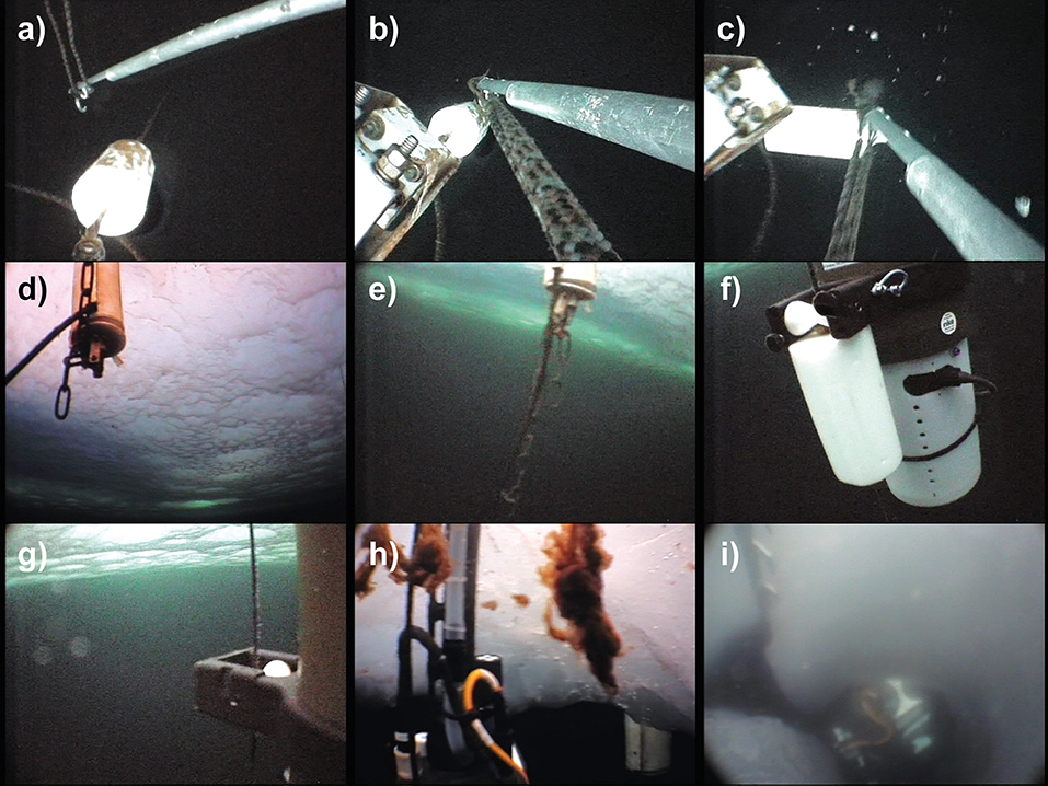
Figure 3. Screenshots taken from the underwater camera during recovery work: (a) Clipping a biner with rope loop into the wire below the top stop. (b) After the biner is clipped into the wire. (c) Taking the load onto the initial recovery system. (d) The attachment chain is fully stretched and pointing upwards, while the umbilical leading to the inductive modem was already cut. (e) After removal of the wire and inductive modem, the chain, and umbilical hang down straight again. (f) Profiler resting on the bottom stop during recovery. (g) Profiler attachment to wire, note the algal contamination on wire. (h) profiler underneath the recovery hole. The floating algal flocks result from biofouling on the wire stripped off by the friction knot. (i) Removing the last ice nose prohibiting profiler recovery with the ice saw (top left image corner). The bright white buoyancy pack of the profiler is already visible under the hole.
Thus, the pole was used to clip a rope loop with a carabiner directly into the profiling wire (Figures 4a,b) underneath the top stopper. With the help of the real-time video, this could be accomplished within a few minutes. Then one end of the rope loop was fastened to a lashing point on the buoy, while the other end was connected to one of the 6:1 pulley systems (Figure 3b) and the weight lifted up (Figure 4c). As the lifting height of one pulley system is typically not enough to lift the attachment point out of the water, an alternating use of two pulley systems grabbing the rope using friction knots (Figure 3c) is necessary. The 6:1 pulley systems were fixed by threading the rope onto the cleats mounted on the tripod legs. Once the clip in point was above the water surface (Figures 3d, 5), the main Klemheist friction knot was installed on the profiler wire. Before the setup could be pulled up further, the wire above the top stopper needed to be cut as now the chain connecting it to the bottom of the buoy was fully tensioned (Figure 4d). The inductive modem needed to be cut loose from its wire to be recovered. Once both these connections were cut loose, the profiler was not fixed to the surface buoy any more (Figure 4e). During the entire procedure, the system should be backed up so that a failure of one element does not result in a complete loss of the system.
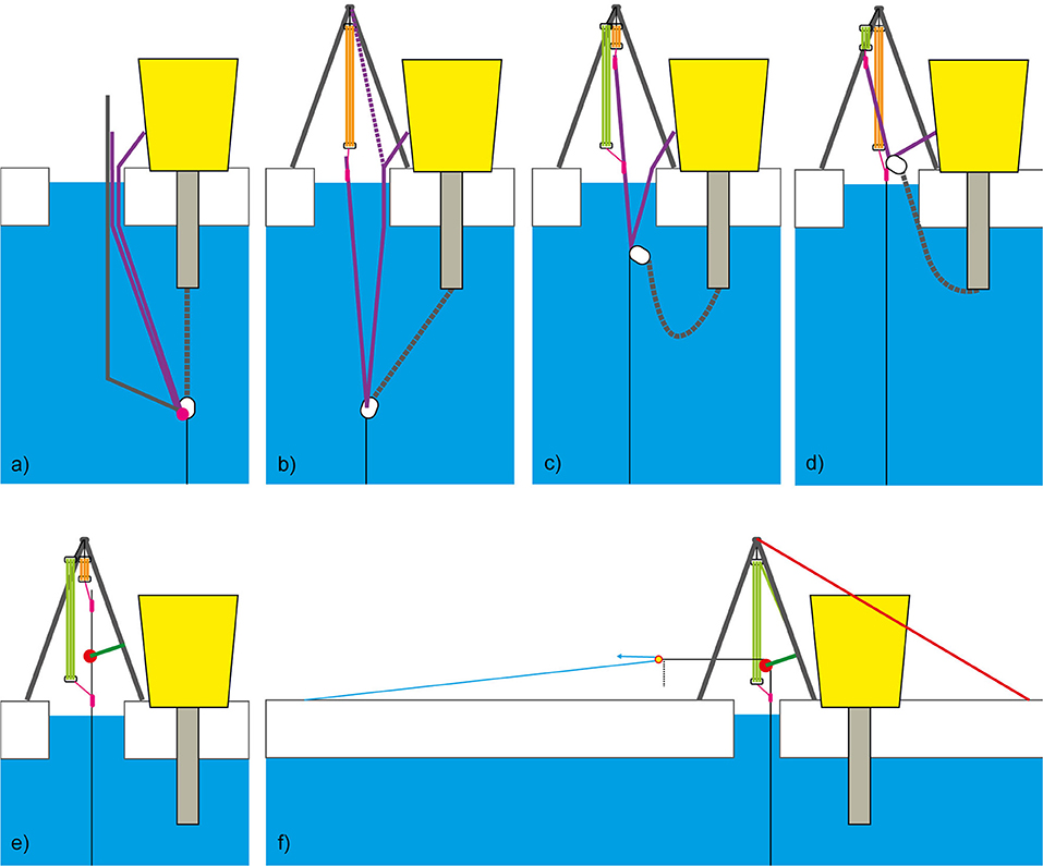
Figure 4. Sketch of the full sequence of the presented recovery technique. (a) Attachment of a rope loop (purple) to the lowermost clippable point. (b) Raising using first pulley (orange). (c) Extension of lifting range using second pulley (green). (d) Mounting a friction hitch (magenta) on the steel wire (black) and cut chain and subsea electronics from wire. (e) Installation of the main friction hitch and diversion pulley (red). (f) Lifting the profiler using a simple 2:1 running loop pulley (light blue).
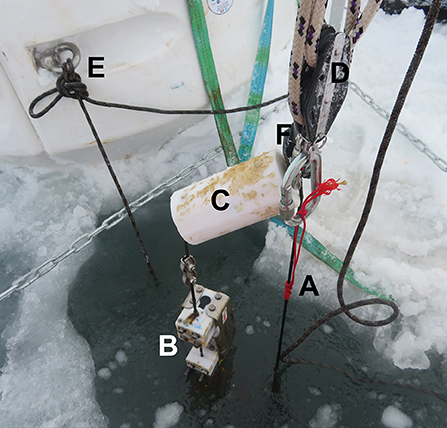
Figure 5. Photograph taken during the recovery at the stage where the main Klemheist friction knot (A) is installed on the main wire. It is attached to the tripod with a 4:1 violin pulley (D). Shortly after the picture was taken, the inductive modem (B) was cut free and the wire cut above the top stop (C). The complete load is currently still hanging on the carabiner (F) and rope (not visible) that was clipped around the wire below the top stop (C) using the clipping arm. The anchor point on the buoy is also visible (E). Note the significant biofouling on the top stop (C) and inductive modem (B).
In cases where the profiler can be commanded through the surface unit to climb to the surface, or when it is by coincidence in its topmost position, it can be retrieved right away. In most cases however, the profiler will be located at depth along the wire, and needs to be pulled up to the surface by lifting up the entire wire until the bottom stopper pushes the profiler to the surface (Figure 4f). While this can in principle be achieved by repeating the step of alternatingly pulling up the line with both high amplification pulleys, this is extremely inefficient and time consuming for normal deployment lengths on the order of hundreds of meters.
To install the more efficient main 2:1 pulley system, the wire was lifted to the top of the tripod and the diversion block was installed on one leg of the tripod (Figure 3e). A second friction knot was installed underneath the diversion block and connected to the extended 6:1 pulley system used as adjustable backup. The wire end was then released from the upper pulley system and connected to a second diversion block, which acted as the loose block in the 2:1 loop haul pulley system. The 50 m rope was now fixed to the ground using two ice screws in 50 m distance from the retrieval hole and threaded through the loose block. The free end was attached to a wooden bar, so that two people could comfortably share the load and pull up the profiling system in 50 m increments (Figures 3f, 6). The pulling was best achieved by walking away from the deployment hole, while a third person was sliding the main Klemheist friction knot (Figure 7) along the wire, so that the load could be taken over by the backup pulley if necessary. Once the diversion block of the loop haul pulley touched the fixpoint of the 50 m rope in the ice, the procedure was repeated by reattaching the diversion loop close to the recovery hole. This process was repeated until the profiler became visible and increasing pulling force indicated that it touched the ice underside (Figures 3g–i). Other pulley systems can also be used, but in our setup, two people were easily able to safely hold and pull the 60 kg ground weight up over the entire wire length of 350 m.
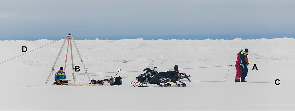
Figure 6. Overview of the recovery procedure. Two persons (A) pull up the load with the 2:1 pulley system. The loop pulley rope is fixed in the ground (C) and diverted in the multiplier block (B). Note the guy rope (D) that is necessary to keep the tripod from tipping over. Picture was taken during the training session, where a bigger tripod was used. No Skidoo was available during the actual recovery.
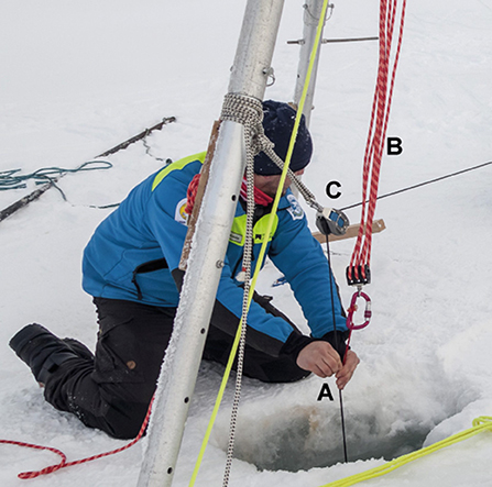
Figure 7. Manual operation of the Klemheist friction knot (A). Note the 6:1 backup pulley with red rope secured to the clamp on the tripod leg (B) and the attachment of the diversion block (C) to the tripod leg. Picture was taken during the training session, where a bigger tripod was used.
In some cases, if the recovery hole is not wide enough for the profiler to fit through, additional drilling or cutting can be necessary (Figure 3i) to extend the hole. Once the profiler is above the surface, the wire can be cut to drop the 60 kg bottom weight if it is not feasible to be retrieved. Time, as well as space and payload limitations in the helicopter did not allow us to retrieve the bottom weight.
In this instance we were recovering a non-working instrument. If however the instrument is still working, it is of highest priority to acquire water samples for in-situ post-deployment calibration of all onboard sensors, in particular the oxygen optodes and bio-optical sensors. A surface sample is rather easy to obtain, however handheld bottle samples from several depths in the upper water column would be preferable in conjunction with a handheld CTD cast if time and logistic constraints allow.
Discussion
Strengths and Weaknesses of the Presented Method
To our knowledge, this is the first time that a sea ice based ocean profiler was retrieved from under the ice without the use of a powered winch system. Despite numerous challenges, the presented technique allows for a fast, safe and efficient retrieval of functional and non-functional wire profilers under polar conditions.
Still many factors need to line up for a successful recovery. This includes the general itinerary of a research ship in the vicinity, as well as the willingness of crew and scientific coordination to support such an operation. Locating a buoy system can prove tricky if time delay in near real time position delivery of the unit is longer than 1 h. In our case, the remnants of the Russian drift camp in the direct vicinity of the buoys made discovery from the air extremely simple and we were lucky enough to have suitable weather for long distance helicopter operations on that day.
However, also a detailed planning of the operation and appropriate qualifications of field workers is crucial to a successful mission. The involved rope techniques might be complicated to perform for people without training, especially if the executing persons do not have excessive background in rope works from either sailing or mountaineering. That being said, these techniques can easily be learned and we thus highly suggest training such recovery operations in a safe and controlled environment. If procedures are just developed on site, time or other environmental constraints might render such a recovery impossible.
A central role is played by the availability of specialized and suitable equipment. The necessary equipment needs to be planned and prepared with care, so that maximum efficiency can be achieved with the minimum amount and thus weight of equipment. Even when ship support is available, insufficient preparation can turn recovery efforts unsuccessful, as one of the authors experienced during an early attempt to manually retrieve the profiler of an ice tethered profiler (ITP93) in autumn 2016 (Boetius and Purser, 2017).
Possible Improvements
One clear improvement would be if equipment for such a recovery is prepared in a customized set before the expedition, which will save a lot of time during on board planning and ease helicopter transport of the components.
The availability of accurate design drawings and measurements of both, the profiler package, as well as the buoy and wire installations enable more accurate planning. This would have enabled us to select the right clip-in point at the first try and potentially helped in judging the necessary diameter of the recovery hole.
Another option to ease recovery if weight and operation limitations allow is the use of portable electric or fuel driven winches. With the increasing use of battery powered tools, winches suitable for this recovery procedure have recently become available at low weight below 10 kg and sufficient power for a profiler recovery hoisting at speeds up to 11.5 m/min (e.g., PCW3000, Portable Winch Co., Sherbrooke, Quebec, Canada).
Implications for Buoy System Design
Our recovery procedure also sheds light on how ice-tethered ocean profiling buoys can be optimized with respect to recovery. In spite of their typical life as expendable equipment, their large cost would justify to include measures for easier recovery.
The design of the connection to the surface buoy is crucial for recovery: First of all we suggest that all ocean profiling buoys should provide an easy way of attaching a hook as low as possible on the installation. In our case this was achieved by clipping the wire below the top stopper. A major problem arises in our recovery technique if the distance between the ice and the surface buoy bottom part is longer than the distance between buoy bottom attachment and the lowermost clippable part. In this case the wire cannot be lifted to the surface (such as in Figure 3d) without opening the original chain link while still under water. We thus suggest to always configure buoy designs in a way that the profiler can be recovered independently of the surface buoy system. This is not only beneficial to situations where equipment in the topside buoy is still working, but also in situations where a recovery of the bulky surface buoy is denied by the logistical constraints. In some situations where the surrounding ice has already melted during summer, it might be helpful to attach a rope directly to the top of the wire, which can be easily reached from the surface and simplifies the work to get access to the main profiler wire. Another possibility to significantly ease recovery is to equip the bottom weight with a simple and inexpensive acoustic releaser, which enables a much less labor-intensive recovery.
Even ship based recoveries could be simplified by these additional measures. Another set of improvements considers the first step of buoy recovery: locating the equipment in the vastness of the Artic. Radio or Radar position beacons, GPS beacons, or remotely (by radio signal) activated flashing lights might significantly ease the location of such equipment from a helicopter if the last available position update is older than 1 h.
If recovery procedures are taken into account during development and deployment, these valuable sea ice-based ocean profilers could be recovered more often. This can be achieved by including additional clip-in points, pre-installed recovery ropes, and choosing appropriate lengths of the different parts of the system connecting wire and buoy.
Summary
We presented a procedure to recover profiler packages as part of ice-tethered ocean profiling buoys without the support of a ship, cranes, or winches. Combining rope techniques from mountain rescue and profiler deployments, we were able to retrieve an extended profiling package from 350 m water depth within <5 h from underneath ice of 1.5 m thickness. The presented technique proved to provide a safe and efficient way of profiler recovery. We demonstrated that it is possible to recover such a profiling system with only four people and without the help of powered lifting equipment under Arctic conditions. To ease future profiler recoveries, we provided a list of necessary equipment, a detailed description of the procedure, as well as suggestions toward further improvements, such as additional clip-in points and matching lengths of different parts of the wire to buoy connection. This hopefully enables more researchers to recover ice-tethered ocean profilers after their completed life cycle and allow for post-calibration of the deployed sensors and thus higher scientific value of the acquired autonomous measurements.
Ethics Statement
Written informed consent was obtained from the individual(s) for the publication of any potentially identifiable images or data included in this article.
Author Contributions
CK prepared the main text of the manuscript as well as all figures, with input from all authors. All authors contributed equally to the planning and execution of the profiler recovery in the field.
Funding
This work and the positions of CK and MH were funded by the Helmholtz Infrastructure Initiative Frontiers in Arctic Marine Monitoring (FRAM) and the Alfred-Wegener-Institut Helmholtz-Zentrum für Polar- und Meeresforschung. Participation of all authors in the AO18 expedition of icebreaker Oden was supported by the Swedish Polar Research Secreteriat (SPRS). The buoys were funded by the French state through the IAOOS Equipex project and the Helmholtz Infrastructure Initiative FRAM.
Conflict of Interest
The authors declare that the research was conducted in the absence of any commercial or financial relationships that could be construed as a potential conflict of interest.
Acknowledgments
We thank the captain and crew of the Icebreaker Oden during the AO18 expedition, the Swedish Polar Research Secreteriat (SPRS), in particular L. Lehnert and Å. Lindgren for their logistical support, as well as Kallax Flyg for enabling this recovery mission. We also acknowledge P. Anhaus, A. Nicolaus, M. Nicolaus, C. Provost, and Nathalie Sennechael for their standby real-time data support during the planning phase, deployment, and recovery operations.
References
Athanase, M., Sennéchael, N., Garric, G., Koenig, Z., Boles, E., and Provost, C. (2019). New hydrographic measurements of the upper arctic western eurasian basin in 2017 reveal fresher mixed layer and shallower warm layer than 2005–2012 climatology. J. Geophys. Res. Oceans 124, 1091–1114. doi: 10.1029/2018JC014701
Boetius, A., and Purser, A. (2017). The Expedition PS101 of the Research Vessel POLARSTERN to the Arctic Ocean in 2016. Bremerhaven: Alfred Wegener Institute for Polar and Marine Research.
Gascard, J. C. (2011). Steps toward an integrated arctic ocean observational system. Oceanography 24, 174–175. doi: 10.5670/oceanog.2011.69
Janout, M. A., Hölemann, J., Waite, A. M., Krumpen, T., von Appen, W.-J., and Martynov, F. (2016). Sea-ice retreat controls timing of summer plankton blooms in the Eastern Arctic Ocean. Geophys. Res. Lett. 43, 12, 493-412,501. doi: 10.1002/2016GL071232
John, M. T., Timmermans, M.-L., and Proshutinsky, A. (2011). The ice-tethered profiler: argo of the arctic. Oceanography 24, 126–135. doi: 10.5670/oceanog.2011.64
Johnson, K. S., Plant, J. N., Coletti, L. J., Jannasch, H. W., Sakamoto, C. M., Riser, S. C., et al. (2017). Biogeochemical sensor performance in the SOCCOM profiling float array. J. Geophys. Res. Oceans 122, 6416–6436. doi: 10.1002/2017JC012838
Kemp, J., Newhall, K., Ostrom, W., Krishfield, R., and Proshutinsky, A. (2005). The Beaufort Gyre Observing System 2004: Mooring Recovery and Deployment Operations in Pack Ice. Woods Hole Oceanographic Institution; Applied Ocean Physics and Engineering (AOP&E).
Kikuchi, T., Inoue, J., and Langevin, D. (2007). Argo-type profiling float observations under the Arctic multiyear ice. Deep Sea Res. Part I Oceanogr. Res. Pap. 54, 1675–1686. doi: 10.1016/j.dsr.2007.05.011
Klatt, O., Boebel, O., and Fahrbach, E. (2007). A profiling float's sense of ice. J. Atmos. Oceanic Technol. 24, 1301–1308. doi: 10.1175/JTECH2026.1
Koenig, Z., Provost, C., Villacieros-Robineau, N., Sennéchael, N., Meyer, A., Lellouche, J.-M., et al. (2017). Atlantic waters inflow north of Svalbard: Insights from IAOOS observations and Mercator Ocean global operational system during N-ICE2015. J. Geophys. Res. Oceans 122, 1254–1273. doi: 10.1002/2016JC012424
Krishfield, R., Toole, J., Proshutinsky, A., and Timmermans, M. L. (2008). Automated Ice-tethered profilers for seawater observations under pack ice in all seasons. J. Atmos. Oceanic Technol. 25, 2091–2105. doi: 10.1175/2008JTECHO587.1
Laney, S. R., Krishfield, R. A., Toole, J. M., Hammar, T. R., Ashjian, C. J., and Timmermans, M.-L. (2014). Assessing algal biomass and bio-optical distributions in perennially ice-covered polar ocean ecosystems. Polar Sci. 8, 73–85. doi: 10.1016/j.polar.2013.12.003
Ludwig, V., Spreen, G., Haas, C., Istomina, L., Kauker, F., and Murashkin, D. (2019). Observation of the 2018 North Greenland polynya with a new merged optical and passive microwave sea ice concentration dataset. Cryosphere Discuss. 2019, 1–36. doi: 10.5194/tc-2019-23
Moore, G. W. K., Schweiger, A., Zhang, J., and Steele, M. (2018). What caused the remarkable February 2018 north greenland Polynya? Geophys. Res. Lett., 45, 13,342-313,350. doi: 10.1029/2018GL080902
Polyakov, I., Timokhov, L., Dmitrenko, I., and Ivanov, V. (2007). Observational program tracks Arctic Ocean transition to a warmer state. Eos Trans. Am. Geophys. Union 88, 398–399. doi: 10.1029/2007EO400002
Schauer, U., Fahrbach, E., Osterhus, S., and Rohardt, G. (2004). Arctic warming through the Fram Strait: oceanic heat transport from 3 years of measurements. J. Geophys. Res. Oceans 109:C06026. doi: 10.1029/2003JC001823
Wadhams, P., Wilkinson, J. P., and McPhail, S. D. (2006). A new view of the underside of Arctic sea ice. Geophys. Res. Lett. 33:L04501. doi: 10.1029/2005GL025131
Webster, S. E., Lee, C. M., and Gobat, J. I. (2014). Preliminary results in underice acoustic navigation for seagliders in Davis Strait. Paper Presented at 2014 Oceans St. John's, 14–19.
Williams, G. D., Maksym, T., Wilkinson, J., Kunz, C., Murphy, C., Kimball, P., et al. (2015). Thick and deformed Antarctic sea ice mapped with autonomous underwater vehicles. Nat. Geosci. 8, 61–67. doi: 10.1038/ngeo2299
Keywords: sea ice, ocean, profiler, buoy, field techniques, retrieval
Citation: Katlein C, Labaste M and Hoppmann M (2019) Manual Recovery of a Sea Ice Based Ocean Profiler. Front. Mar. Sci. 6:649. doi: 10.3389/fmars.2019.00649
Received: 04 July 2019; Accepted: 04 October 2019;
Published: 01 November 2019.
Edited by:
Johannes Karstensen, GEOMAR Helmholtz Center for Ocean Research Kiel, GermanyReviewed by:
Urmas Lips, Tallinn University of Technology, EstoniaDariia Atamanchuk, Dalhousie University, Canada
Copyright © 2019 Katlein, Labaste and Hoppmann. This is an open-access article distributed under the terms of the Creative Commons Attribution License (CC BY). The use, distribution or reproduction in other forums is permitted, provided the original author(s) and the copyright owner(s) are credited and that the original publication in this journal is cited, in accordance with accepted academic practice. No use, distribution or reproduction is permitted which does not comply with these terms.
*Correspondence: Christian Katlein, Y2thdGxlaW5AYXdpLmRl