 Yingzhou Liu1,2
 Wei Shi
- 1State Key Laboratory of Coastal and Offshore Engineering, Dalian University of Technology, Dalian, China
- 2Institute of Earthquake Engineering, Faculty of Infrastructure Engineering, Dalian University of Technology, Dalian, China
- 3Deepwater Engineering Research Center, Dalian University of Technology, Dalian, China
- 4Renewable Energy Engineering Institute, PowerChina Huadong Engineering Corporation Limited, Hangzhou, China
The interaction between vertical offshore wind turbine (OWT) and sea ice with fluid is a complex process including local and global crushing of ice fragments and vibration of OWT. It is crucial to study the ice resistance of OWT structures considering the fluid-structure interaction (FSI). This article investigates a complete process of dynamic sea ice-monopile OWT interaction considering soil-structure interaction (SSI) and FSI effects. A fully coupled dynamic collision model of sea ice and OWT incorporating with the explicit non-linear collision tool ANSYS/LS-DYNA is proposed. The simulated ice loads in this study is verified by different simulation methods and international static ice force standards closely related to ice dynamic characteristic parameters. Then, the dynamic response and damage of the OWT structure during ice-structure interaction are studied using the fully interaction model with FSI coupling. The simulated ice force can produce a significant vibration response in the structure coupling with FSI due to occurrence of ice-induced resonance in the ice velocity range of 2.5–3.5 cm/s. Finally, the effect of fluid on the sea ice-OWT interaction in the initial velocity collision of sea ice is analyzed. FSI coupling can cause a certain level of collision hysteresis, accelerate the failure of sea ice breaking and reasonably reduce the energy of the structure.
Introduction
In the recent years, with the rapid development of new and renewable energy (Seeking et al., 2021; Zhao et al., 2021; Ren et al., 2022), offshore wind power industry is fast developing due to its high wind speed and less turbulence, less visual impact (Sun et al., 2012; Wang et al., 2022) comparing with onshore wind farms. The global installed capacity of offshore wind power has reached 29 GW by 2020, which is expected to reach 50 GW by 2024 (Global Wind Energy Council [GWEC], 2020). Ice load is an important design load for offshore wind turbine (OWT) structures in cold regions and the interaction between sea ice and vertical structures is a complex non-linear dynamic behavior. Therefore, the research of sea ice collision on OWT structures is required to predict the ice loads and analyze the dynamic performance of OWTs accurately ensuring safety operation.
Current design specifications mainly focus on static ice forces; hence, the dynamic ice-structure interaction is calculated as the upper-bound limiting ice force based on static values, which does not reflect the ice non-linear behavior and the whole process of ice-structure interaction. Many studies in this field were based on model tests and full-scale experiments. Yue and Bi (2000) shown that the collision between sea ice and vertical structures often causes crushing or buckling failure, among which crushing failure is relatively larger and would cause ice-induced vibration. The frequency of ice loads with varying breaking lengths in full-scale was studied by Suominen et al. (2017). The accuracy of the numerical calculations was verified utilizing a series of ship-breaking tests on artificial ice floes of polypropylene material by Yang et al. (2021). Through full-scale measurements, Herrnring et al. (2020) found that the failure mode of ice mainly depends on the test speed and the ratio of the gap height to the sample diameter is the most important parameter that affects the load level.
With the rapid development of numerical simulation technology, non-linear dynamics calculation methods have been gradually introduced in the research of sea ice and OWT collision problems. A non-simultaneous ice force model of sea ice acting on a vertical OWT structure was proposed by Zhou et al. (2019); the results showed that the proposed numerical model can capture the main trends of ice-wind turbine foundation interaction. Jaakko and Simo (2017) studied different load combinations when coupling wind, ice and structure. Ye et al. (2019) conducted a fully coupled simulation of the national renewable energy laboratory (NREL) 5 MW OWT under the action of turbulent wind and ice-induced vibrations based on the multi-body dynamics method and the ice-induced vibrations were shown to have a significant influence on OWTs. Shi et al. (2016) studied the dynamic interaction of a monopile OWT and horizontal ice under parked and operating conditions using a semi-empirical numerical sea ice model in coupled with the OWT model. Kuutti et al. (2013) used a viscous surface method to establish the ice-structure interaction model to simulate the interaction between ice and a rigid vertical structure. They indicated that the high-pressure zone type of contact has a significant impact on the crushing failure of sea ice. Although the dynamic characteristics of OWT structures were considered in the above studies, the ice loads in the numerical simulations were so simplified that the failure state of the ice floe during the collision and the process of ice-structure interaction could not be revealed. In addition, the fluid-structure interaction (FSI) effects are ignored.
The seawater can produce an additional inertial force on the ice sheet and affect the vibration of the structure, which can reversely affect the fragmentation of sea ice forming a coupled vibration system of ice-water-structure. Therefore, Caraeni et al. (2020) presented an extended-finite element method (FEM) approach to simulate the solidification phenomenon and liquid-solid phase transition behavior. Ji et al. (2013) used the discrete element method (DEM) to analyze the breaking process of sea ice in front of the vertical structure, which simply considered the drag force of seawater. A simplified numerical model capable of analyzing the dynamic interaction process of an elastic-plastic struck plate wall of a fluid tank subjected to wedge impact was presented by Zhu et al. (2020). It was found that the movement of water causes part of the impact energy to be dissipated, thereby helping to reduce the structural deformation. Based on Open FOAM, Huang et al. (2019) achieved FSI coupling to simulate aqueous elastic wave-ice interactions indicating the proposed model capable of capturing ice breaking phenomena. In summary, the influence of FSI should be considered in the dynamic response analysis of OWTs under ice.
Studies on the effect of FSI coupling of sea ice-offshore structure and sea ice-ships interaction are scarce, but they are gradually developing in the recent years. Huang and Zhang (2017) calculated the added mass coefficients of floating ice based on ANSYS/LS-DYNA and WADAM and showed that the model coupling with FSI in LS-DYNA can give better numerical results in terms of hydrodynamics. The ice breaking process of ships coupling with FSI based on the CFD-DEM method was obtained by Huang and Tuhkuri (2019). They observed that this model can better predict the ice resistance of ships. However, currently no research was found done on sea ice-OWTs interaction with FSI.
In this article, a numerical model is first developed to simulate a fully coupled dynamic interaction process of sea ice and a NREL 5 MW monopile OWT considering FSI effect. The main focus is the impact of FSI coupling in the brittle crushing failure of sea ice caused by high-speed collision with the monopile OWT and the dynamic response of OWTs. The proposed interaction model can represent the dynamic characteristics of the non-linear behavior during collision. It is worth noting that the sea ice constitutive model uses an elastic-plastic fracture model, which has been well validated on the interaction of horizontal ice and marine structures (Daniel et al., 2012). Further, the ice loads are compared with the design loads from international electrotechnical commission (IEC) standards (International Electrotechnical Commission [IEC], 2009), DEM, and the correctness of the proposed method to simulate the ice force is verified. Finally, the dynamic response and damage of monopile OWTs are investigated and the effects of FSI on the energy variation of the OWT structure and ice force are demonstrated under initial velocity of ice.
Numerical Theory
Equation of Motion
The interaction between sea ice and structure is a complex non-linear dynamic process. According to the structural dynamics, the equation of motion of the sea ice collision problem can be expressed as:
where [M] is the mass matrix; [C] is the damping matrix; [K] is the stiffness matrix; is the acceleration vector; is the velocity vector; {x} is the displacement vector and {Fc} is the sea ice collision force vector. Fc can be described as:
where Fs (h) is the static ice force and Fd is the dynamic ice force assumed to be a Gaussian process with a mean value of 0. The static ice forces can be described as:
where m is the collision surface shape factor (0.9 for circular cross section); σc is the compressive strength of sea ice; D is the structural outside diameter; I is the embedding coefficient and fc is the contact coefficient. For cylindrical structures with a diameter of 2.5 to 10 m, the coefficient I⋅fc is 0.4, according to the offshore standard IEC 61400-3 (International Electrotechnical Commission [IEC], 2009).
The Eq. 1 can be solved numerically to obtain the transient response of the sea ice collision problem. The explicit integration using the central differential method was used to calculate the accelerations, the collision forces and the structural internal forces.
Fluid-Structure Interaction Theory
Arbitrary Lagrange-Euler (ALE) and Euler algorithm are the commonly used methods in the simulation of FSI. According to the ALE algorithm, the meshed elements of the sea ice can be moved and co-existed with each other, rather than being fixed in one position. So, the consistency should be ensured by the continuities between the displacements and pressures on the contact surface of the fluid and ice, rather than the consistencies between the meshed fluid and solid elements. The velocity potential in the fluid domain can be introduced with Laplace’s equation in Eq. 4.
Further, the deformation continuum condition of the contact surface between fluid and sea ice can be expressed as:
In the ALE method, in addition to Lagrangian and Euler coordinates, another reference coordinate assumption needs to be defined. The derivative of any physical quantity f with respect to time t consists of two parts:
where Xi and xi are Lagrangian and Euler coordinates and wi is the relative velocity. The governing equation of the fluid is derived based on the Navier–Stokes equation of incompressible fluid (Huang and Tuhkuri, 2019; Tang et al., 2020) and Eq. 6.
As a conservation of mass and momentum, it can be written as Eqs 7 and 8 using the ALE algorithm.
Thereafter, the conservation of energy can be expressed as:
Concurrently, for solid, the governing equation is required when moving solid elements are as follows:
where ρ is the density; , , and are the velocity, acceleration and grid velocity of the material, respectively; is the Cauchy stress; FV is the volume force and e is the energy.
In LS-DYNA, the Euler description is used for the fluid solution and the Lagrangian description is used for the OWT structure and ice. The process of solving the FSI force is to solve the interaction between the both and the most common penalty method is also used for the solution method. Therefore, the coupling mechanism of fluids and solid can be achieved by solid-fluids penetration, in which a spring representing the pushing FSI force F is placed at a fluid node with the fluid penetrating depth Δd into the solid. The FSI force at the node can be expressed as a product of stiffness and penetration depth:
where pf is the coefficient of the penalty function; K is the volume modulus of the fluid element; V is the volume of the fluid element and A is the average area coupled with the fluid element.
The seawater is described by the Grüneisen state equation, which calculates the material compression force by defining the pressure volume. Based on the Grüneisen equation, the water pressure equation can be expressed as:
where ρ0 and ρ1 are the initial density and current density of the fluid, respectively; C is the velocity of sound shock wave; γ0 is the Grüneisen constant; α is the first-order correction factor of γ0; EC is the fluid-specific internal energy; μ is the coefficient of fluid viscosity and S1, S2, and S3 are the massless coefficients associated with the shock wave propagation.
Material Models
Sea Ice Constitutive Model
The von Mises yield criterion is applied to determine the plastic phase of sea ice and the failure criterion of maximum failure strain and cut-off pressure are applied to determine the failure of sea ice. Meanwhile, the isotropic elastoplastic fracture characteristic is chosen as the constitutive model of ice. The sea ice presents an elastic behavior before reaching the yield state. After the first crack, the ice presents linear softening behavior with the developing of cracks. Finally, the ice exhibits a viscous fluid state when the crushing failure is completed (Derradji-Aouat, 2005). Based on the data from references (Song et al., 2019), the selected sea ice parameters are given in Table 1.

Table 1. Sea ice parameters.
Offshore Wind Turbine Properties
The NREL 5 MW monopile OWT is used in this study to investigate the interactions between the sea ice and vertical structures (Jonkman, 2005), as shown in Figure 1. The global coordinate system is located at the intersection of the wind turbine center and the mean sea level (MSL) with the x and y directions corresponding to the downwind and horizontal directions, respectively.
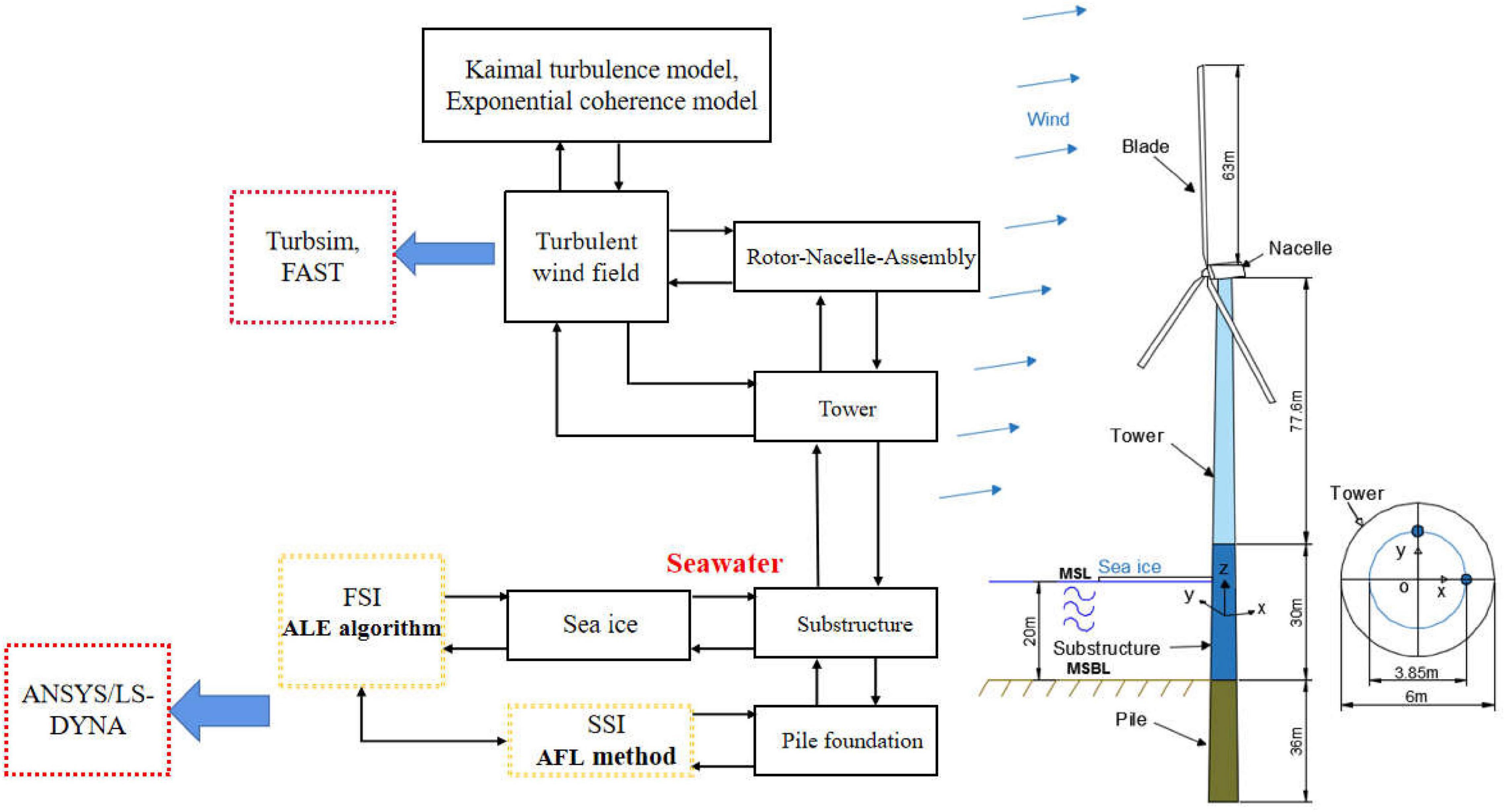
Figure 1. Schematic diagram of the national renewable energy laboratory (NREL) 5 MW monopile offshore wind turbine (OWT).
The rotor nacelle assembly (RNA) is supported by an extended tower with a height of 77.5 m placed on top of the monopile supporting structure. The water depth is selected as 20 m and the fluid parameters used in Eq. 12 are shown in Table 2. The material density for the tower is set to be 8,500 kg/m3 instead of the default value of 7,850 kg/m3 to account for the additional mass of flanges, bolts, internal equipment, paint, mass of secondary structures, etc.
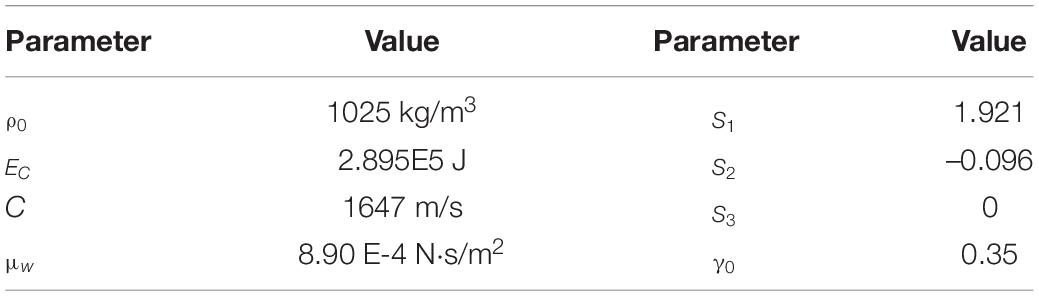
Table 2. Fluid parameters applied in the Grüneisen equation.
The fully ice-OWT interaction analysis process is given in Figure 1. The IEC Kaimal turbulence model and the exponential coherence model are used to generate turbulent wind field inputs with a turbulence intensity in category A by TurbSim (Kaimal et al., 1972) and wind turbine loads can be calculated through FAST. Furthermore, the apparent fixity length (AFL) method is used herein to consider the soil-structure interaction (SSI) effect. In the AFL method, the properties of the fictive beam are tuned such that the mudline displacement and rotation for both the models would be the same, when loaded by a mudline shear force and bending moment that are representative. The fictitious length in the AFL method is 17.5 m, which is 2.9 times of the diameter of the monopile foundation.
Verification
Ice Constitutive Model Verification
In the analysis of ice-OWT interaction, the constitutive model of ice is the key for the simulation. When sea ice collides with an OWT, the interaction area of the ice sheet will be locally crushed and broken after cracks in the ice sheet. In order to verify the correctness of the sea ice model used in this study, a simple rigid column and sea ice collision numerical model are established and a theoretical pressure-area relationship proposed by Masterson and Frederking (1993) in international organization for standardization (ISO)-ALIE (International Organization for Standardization [ISO], 2010) is adopted to compare calculation results using such ice constitutive model. The calculated contact pressure is verified against ISO-ALIE (Figure 2). It is shown that the collision pressure can be expressed as an inversely proportional function of the collision area under the static ice forces and the comparison results are more consistent indicating the ice numerical model could be further used for FSI analysis.
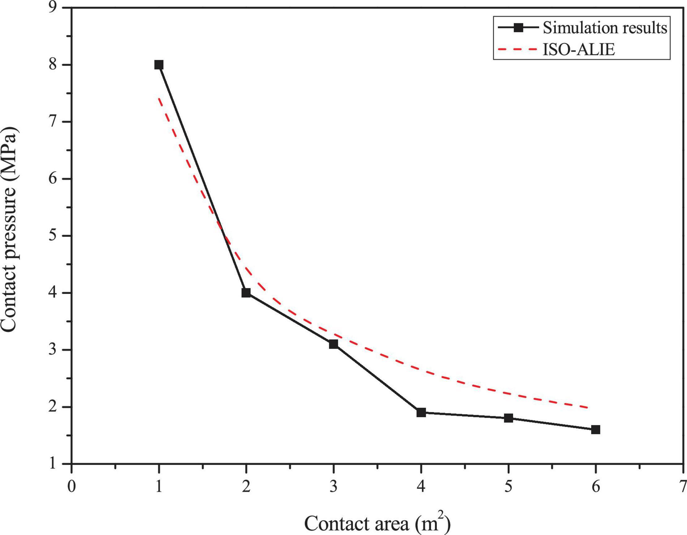
Figure 2. Comparison of the simulation results with international organization for standardization (ISO) specifications for different contact areas.
Verification of Ice Parameters
In order to verify the influence of the main constitutive and failure parameters of sea ice on the ice-OWT interaction, numerical simulations of the interaction between sea ice and NREL 5 MW monopile OWT are carried out. In the simulations, different failure strains, failure pressure and plastic hardening modulus are considered. The detailed parameters are shown in Table 1. The plastic hardening modulus EP is related to the elastic modulus E and the tangential modulus Etan:
Figures 3–5 show the comparisons of the ice forces with the different ice parameters in Table 3. The extreme, mean and SD ice force all increase linearly with the increasing ice parameters. The fitted linear relations in the graphs show that the maximum load can generate the largest slopes and the fastest growth rates. The slopes of the maximum dynamic ice forces under the influence of failure strain and the failure pressure are 3.5356 and 3.4955, which are significantly greater than the influence of plastic hardening modulus, while the SD curves are not extremely different. The detailed comparisons of the mean, SD and extreme ice load values are shown in Tables 4–6.
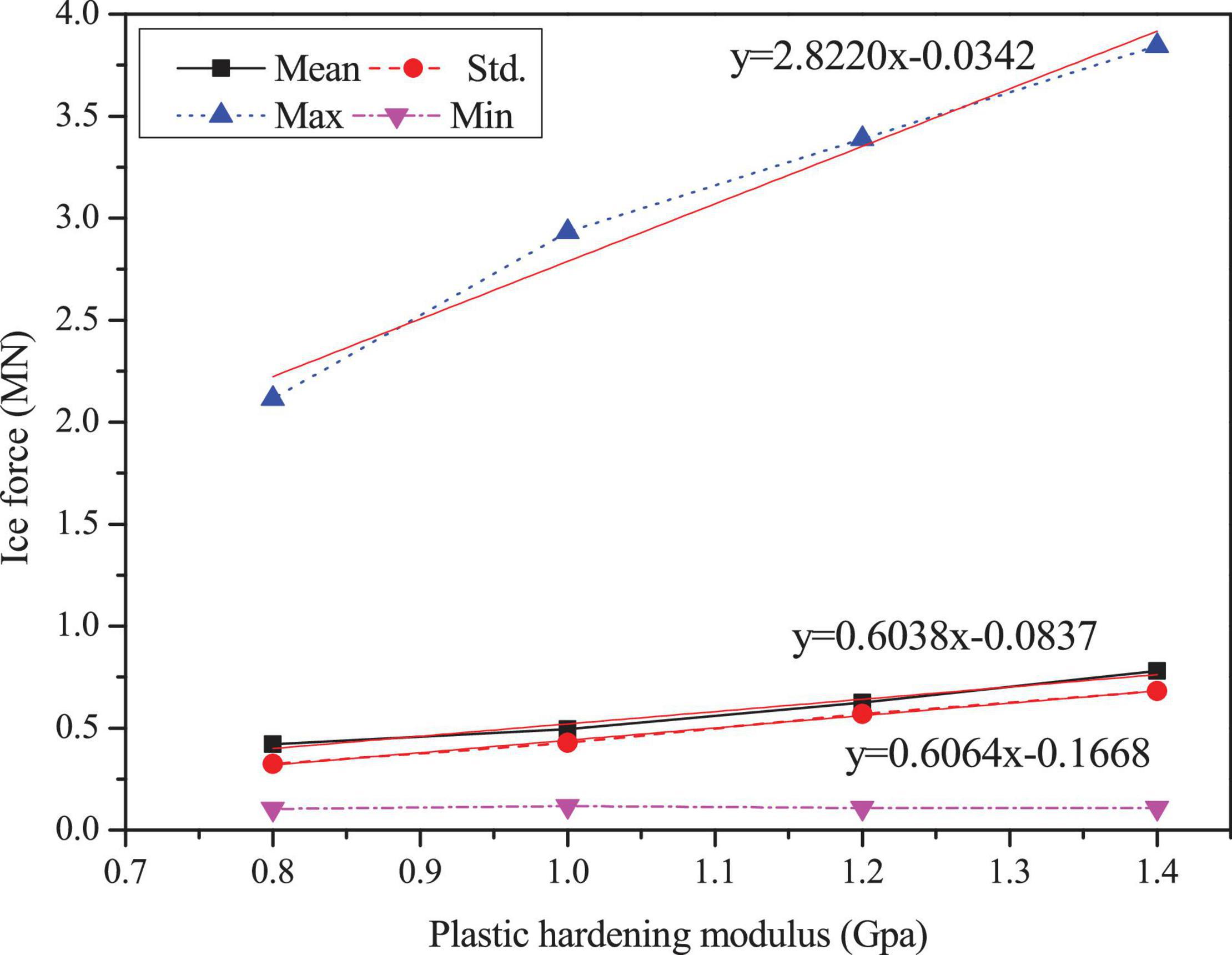
Figure 3. Statistic results of the ice force in the F-A direction with variations of plastic hardening modulus.
Figure 4. Statistic results of the ice force in the F-A direction with variations of failure pressure.
Figure 5. Statistic results of the ice force in the F-A direction with variations of failure strain.
Table 3. Parameters for simulation analysis of sea ice effects.
Table 4. Comparison of the ice forces for the simulations with different plastic hardening modulus.
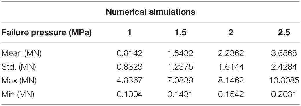
Table 5. Comparison of the ice forces in the simulations with different failure pressures.
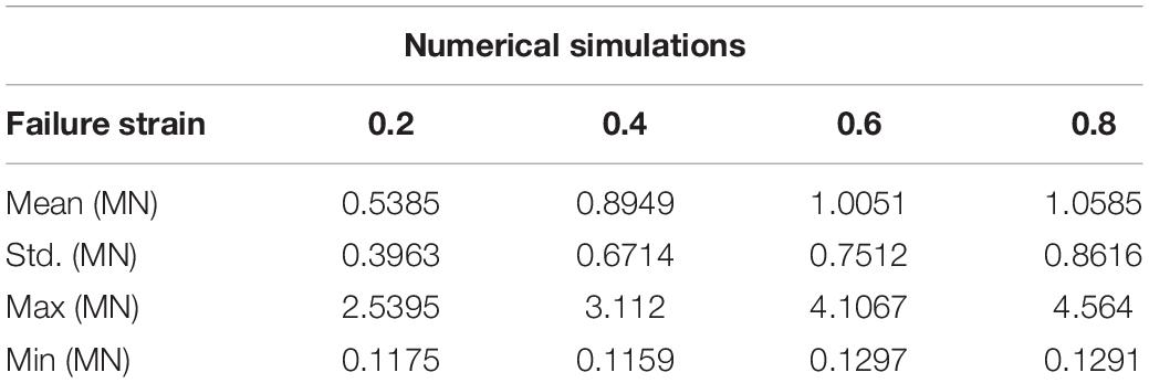
Table 6. Comparison of the ice forces in the simulations with different failure strains.
In summary, the effect of plastic hardening modulus, failure pressure and failure strain of ice are significant in influencing ice force; therefore, these variations can play an important role in numerical simulations. Based on the data from references and the discussion of ice parameters above, the sea ice parameters selected are shown in Table 1. The failure strain value of 0.3 is used to simulate the crushing failure of sea ice.
Collision Force Analysis With Fluid-Structure Interaction
Numerical Model With Fluid-Structure Interaction Coupling
The interaction numerical model with FSI consists of three main parts: the sea ice, NERL 5 MW monopile OWT and seawater. The fluid model is 80 m × 72 m (length × width) with 20 m depth of water, which is naturally modeled by null materials with non-reflecting boundary (infinite boundary condition), as shown in Figure 6A. Considering the large amount of computational effort FSI requires, the fluid-solid element mesh is no longer refined. Instead, a separate overlapping modeling approach is applied to divide the sea ice and the fluid model into Lagrangian meshes and Euler meshes, respectively, so that the two meshes can overlap and move spatial freely.
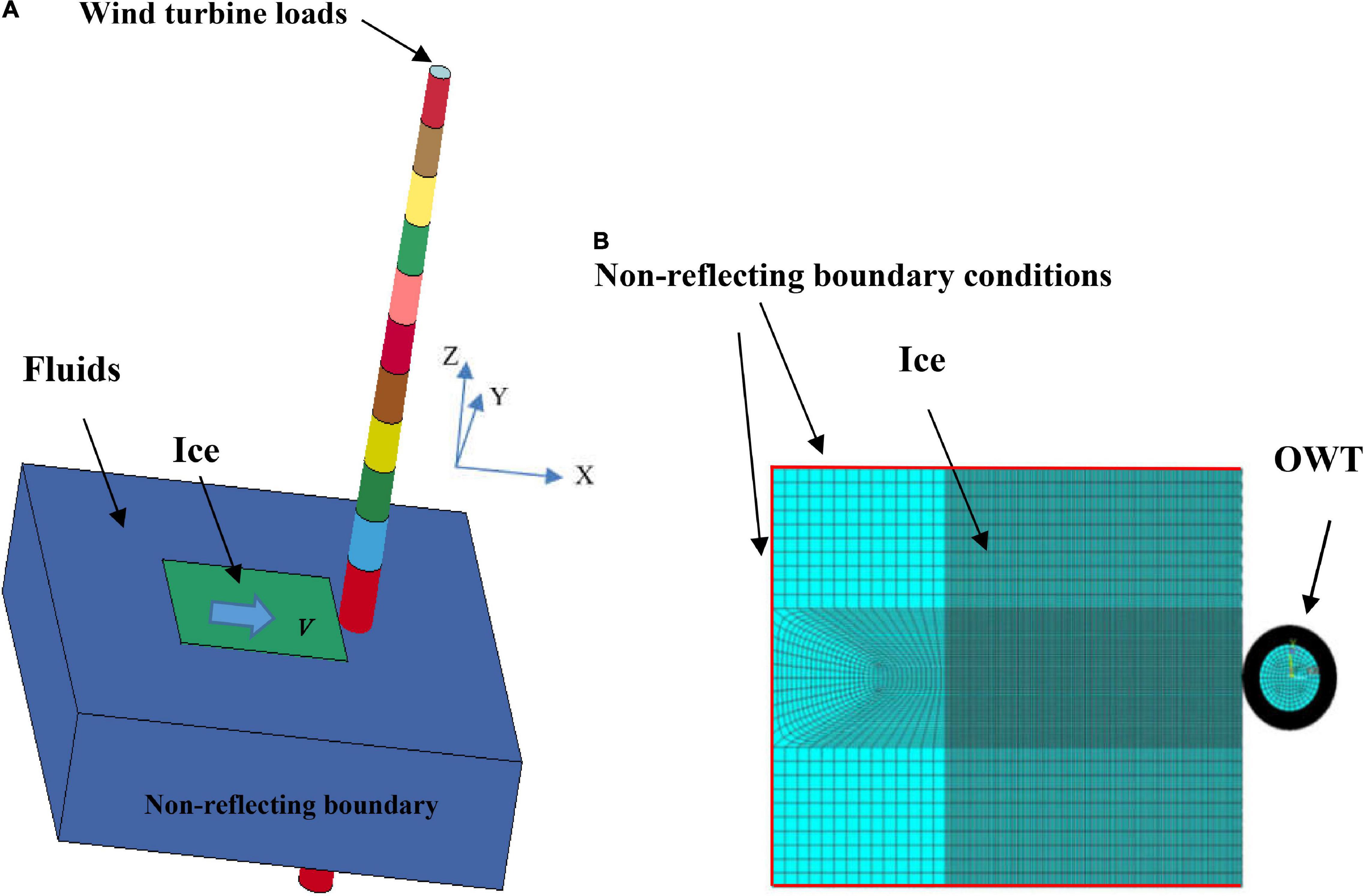
Figure 6. Sea ice and the OWT interaction model with fluid-structure interaction (FSI) coupling. (A) Sea ice-OWT interaction model with FSI coupling; (B) Schematic of the sea ice-OWT interaction.
The three-dimensional effect and meshing of the interaction between sea ice and the OWT with FSI coupling are given in Figure 6. It is worth noting that F-A and S-S directions of OWTs are defined under the coordinate system (X, Y, and Z), as shown in Figure 6. The F-A direction is along the X direction, i.e., the sea ice drifting direction and the S-S direction is along the Y direction. As indicated in the figure, the ice model is immersed in a non-viscous, non-rotating and incompressible fluid and the sea ice is discretized using fully integrated solid elements. In order to prevent the ice boundary condition affecting the stress wave reflection, the outer boundary of the ice solid element adopts the non-reflecting boundary condition to ignore the ice size and shape effect, as shown in Figure 6B. Furthermore, to avoid an hourglass phenomenon caused by explicit integration calculations in ANSYS/LS-DYNA, the Flanagan–Belytschko stiffness method is applied to evaluate whether the calculation process produces an hourglass. The contact between the sea ice and the structure is set as the eroding surface-to-surface contact. This contact condition ensures that the remaining elements can still be considered after crushing and removal of the crushed elements.
Concurrently, the SHELL163 element is used to establish the plastic kinematic model of the steel and the RNA of the OWT is simplified as a concentrated mass, which is applied to the wind turbine loads calculated by FAST and wind turbine loads include shear force in F-A direction and bending moment around S-S direction. In order to ensure the accuracy of numerical simulation, while improving computational efficiency, the mesh elements are only encrypted at the location of the ice crushing and structure collision, which are 0.15 and 0.2 m for the ice and OWT, respectively.
During the fully ice-OWT with FSI interaction simulation, the OWT structure is defined as Lagrangian element, and the seawater are ALE elements. The ALE algorithm and contact collision algorithm in LS-DYNA are used to couple ice-seawater, OWT-seawater and ice-OWT collision settings. In addition, if the structural grid of ice overlaps with that of seawater, in order to avoid the hydrodynamic solution error caused by the overlapping of different material grids, the seawater material occupying the ice area should be removed.
Dynamic Ice Force Analysis
The dynamic ice forces simulated from the numerical model with FSI in this study are compared with the dynamic ice forces obtained by the DEM (Ji et al., 2013); dynamic ice forces calculated by the semi-empirical formulation using ice force spectrum were proposed by Kärnä and Qu (2004) and the static ice force formulas in the IEC standard.
The simulated ice force from the proposed FEM, together with ice force spectrum fitting and the DEM are compared against the design values, was calculated by the Korzhavin formula, IEC standard, as given in Figure 7. For the static ice force, the ice force from present method provides better approximations with results closest to the IEC formula, the difference of maximum ice force is only 391 kN. Furthermore, the American petroleum institute (API) standard gives the more conservative upper bound of the maximum ice force design value, which can attain 3,600 kN. On the other hand, the mean ice force of three dynamic methods, namely, present FEM, DEM and ice force spectrum fitting method are 727.93, 374.29, and 833.57 kN, respectively, and the ice force amplitude obtained by DEM is the smallest related to other two methods. It can be seen that proposed FEM in this study basically consistent with the simulation result of ice force spectrum fitting method. On the basis of the above discussion, the interaction simulation of ice and OWT through proposed method in this article can be well verified.
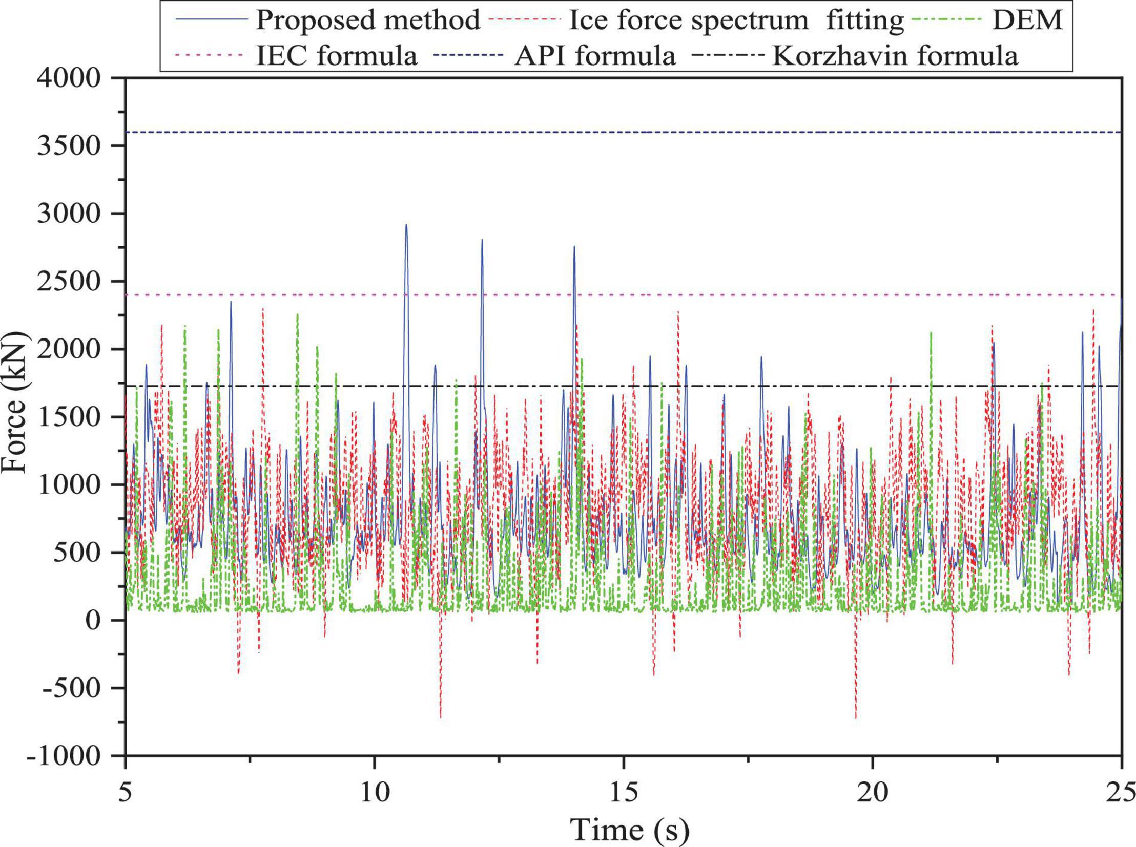
Figure 7. Ice force time history.
Results
In this section, the structural dynamic response and damage of the OWT with FSI are investigated. Moreover, the influence of the FSI on ice-OWT interaction is discussed through the load case, as shown in Table 7. It worth noting that LC 1.1 is used to investigate structural dynamic response and damage of OWT with FSI, while LC 1.2 is used to study influence of the FSI on ice-structure interaction.

Table 7. Load cases (LCs) to research ice-OWT interaction with FSI.
Structural Dynamic Response and Damage Analysis
The structural responses are in the form of forced vibrations. The displacement at the collision area of the OWT supporting structure under LC 1.1 is shown in Figure 8. In the F-A direction of the OWT, which is the primarily loaded direction, the displacement at the collision area on the supporting structure can reach the maximum of 0.086 m. In addition, the structural responses in the y direction are larger compared with z direction, although both of which are at a low level of structural responses.
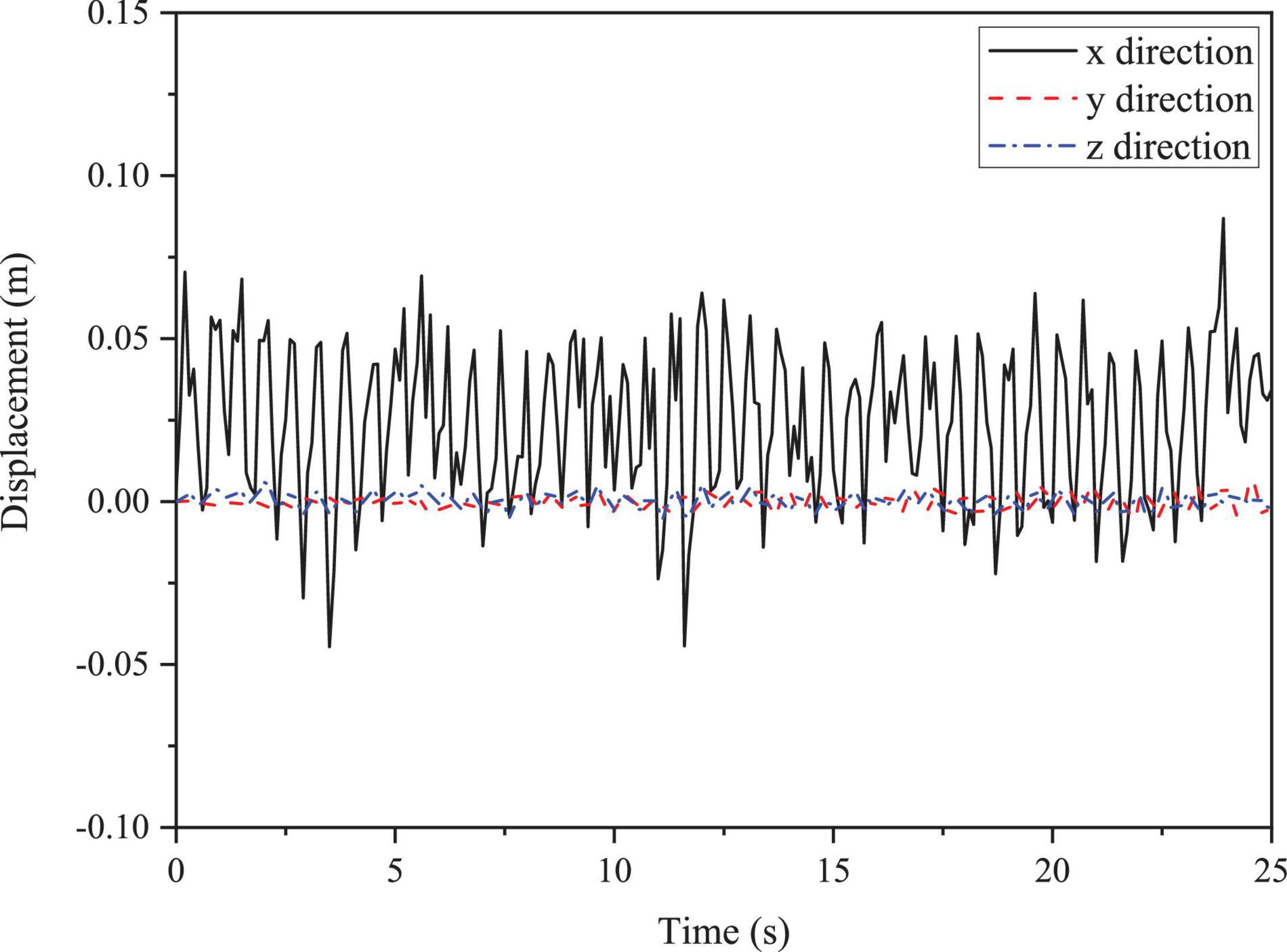
Figure 8. Three directions of displacement at the collision area of the structure.
The effective stress damage distribution of the structure at different moments is shown in Figure 9. As indicated in Figure 9A, the main damage to the OWT occurs only within the collision zone of contact, with little or no damage occurring at other locations. As the collision progresses in Figure 9B, the damage surface of the structure gradually spreads to the surrounding area. At 19.8 s, the effective stress continues to increase slowly and the damaged surface area gradually stabilized in Figure 9C. The collision mainly occurs in the elastic phase within the material failure strain value of 0.348; therefore, no failure occurs at the collision area.
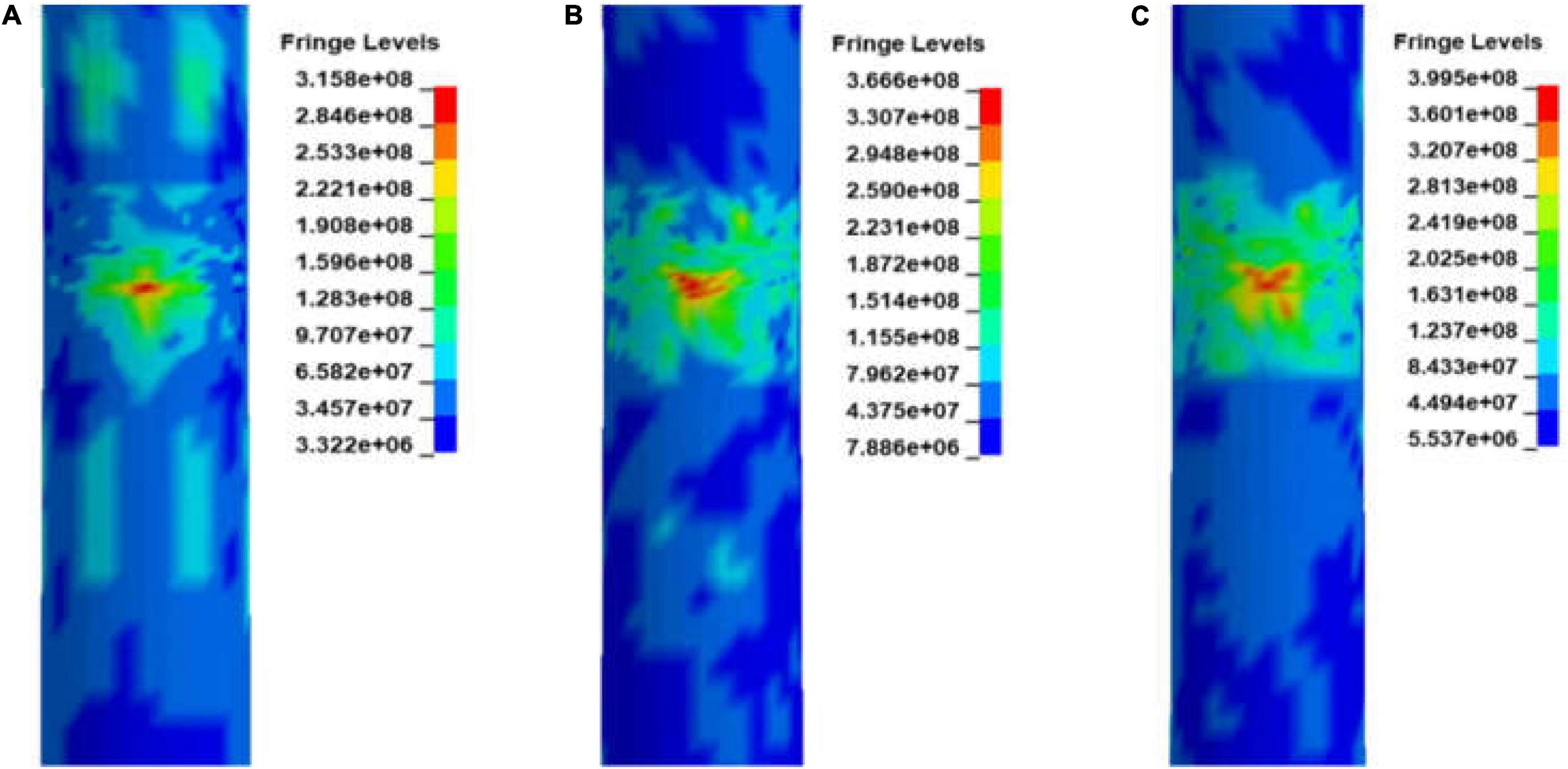
Figure 9. Effective stress damage distribution diagrams at three moments. (A) Structural effective stress distribution at 1.5 s; (B) Structural effective stress distribution at 10.2 s, and (C) Structural effective stress distribution at 19.8 s.
On the other hand, the breaking of sea ice is also important in OWT structural design. It may cause ice-induced resonance generating a large ice force resulting in a severe vibration response of the structure. The main frequency of sea ice loads is between 0.2 and 0.84 Hz (Liu and Ji, 2018), which covers the fundamental frequency of the monopile OWT, therefore ice-induced resonance analysis, i.e., structure steady-state vibration is required. Numerical simulations with FSI are performed to provide the velocity range of the possible ice-induced resonance.
Zhang (2002) pointed out that the self-excited vibration of sea ice at ice velocities of 1–2 cm/s can lead to steady-state vibration of marine structures. The results shown in Figure 10 indicate that steady-state vibration of the structure is of high probability to occur when the sea ice velocity is in the range of 2.5–3.5 cm/s. The simulation results are consistent with the measured data in Zhang (2002) and Zhang et al. (2018).
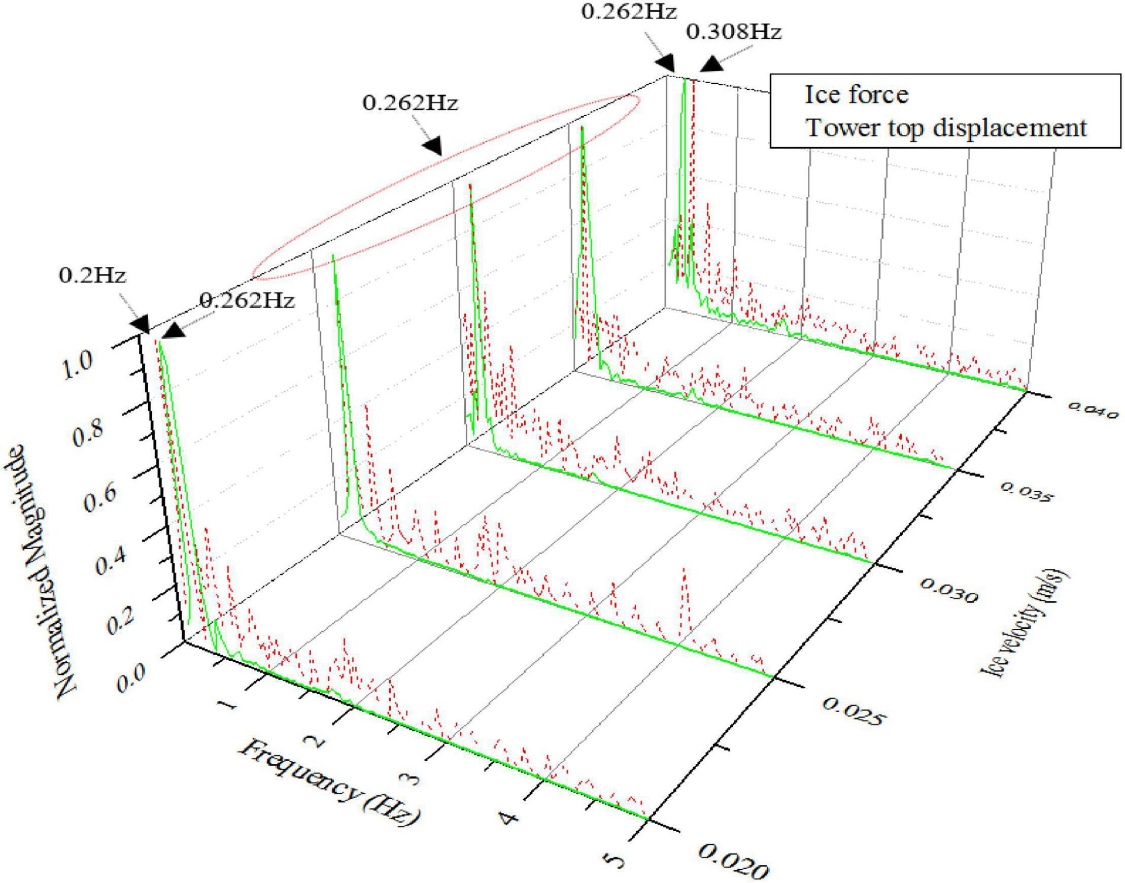
Figure 10. Frequency domain characteristics of the structure displacement and ice force.
Influence of the Fluid-Structure Interaction on Ice-Structure Interaction
The FSI effect includes the influence of seawater on OWTs and ice. To systematically explore the effect of fluid in full collision process, ice-OWT interaction numerical simulations are studied with the initial velocity of ice, as given in LC 1.2 of Table 7. Comparable cases of coupling and without coupling FSI are considered. Further, the collision force and energy variation are compared in terms of effect of FSI.
The ice-OWT interaction is performed at an initial velocity of 1.2 m/s in LC 1.3. The time history of the collision force with and without FSI is shown in Figure 11 where the general trend of the two cases mostly follow the same route, while the case with FSI shows an obvious hysteresis. The ice force with FSI fluctuates more frequently than that without FSI coupling because of the large number of element failures in the sea ice caused by FSI. The maximum ice force with and without coupling is 0.458 and 0.569 MN, respectively, indicating that the fluid can impair the load within the allowable error range. The ice force reaches its maximum between 0.8 and 1.2 s, which can be corresponded to the larger growth and the fluctuations in sea ice erosion energy. Thereafter, as the structural deformation and the collision force continue to increase, the sea ice slows down and finally bounces back with ice force gradually decreases until unloading completed. Therefore, the seawater can affect not only the ice force amplitude, but also the interaction duration, i.e., lowering the maximum ice force and lengthening the duration of the interaction.
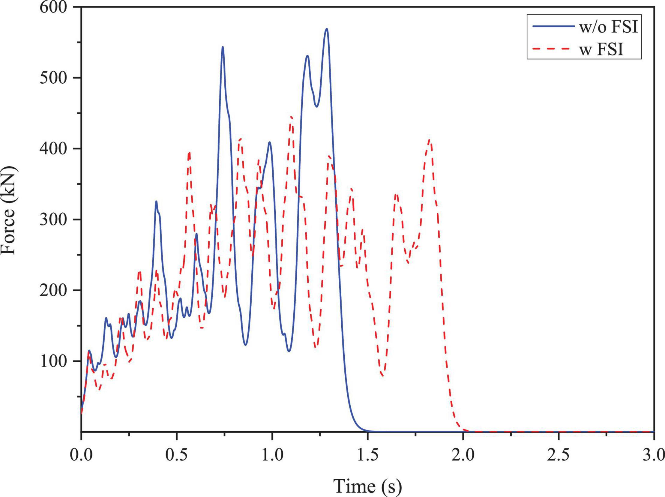
Figure 11. Comparison of ice force time history.
The energy variation of the collision system is analyzed to understand the fully coupled collision process. The system energy shown in Figure 12A satisfies the law of energy conservation. The energy exchange process goes from a transient state to a steady state during the extrusion of the sea ice and the OWT structure. The system energy mainly consists of kinetic energy and internal energy. The kinetic energy drops rapidly to a minimum inflection point of 0.027 MJ at approximately 2 s after the ice floe coming into contact with the structure. It means that the ice velocity gradually decreases to zero at this moment. After the sea ice bounces back, the kinetic energy of the collision system becomes stable and gradually decreases to the minimum value. Additionally, the internal energy of the system increases slowly and gradually stabilized.
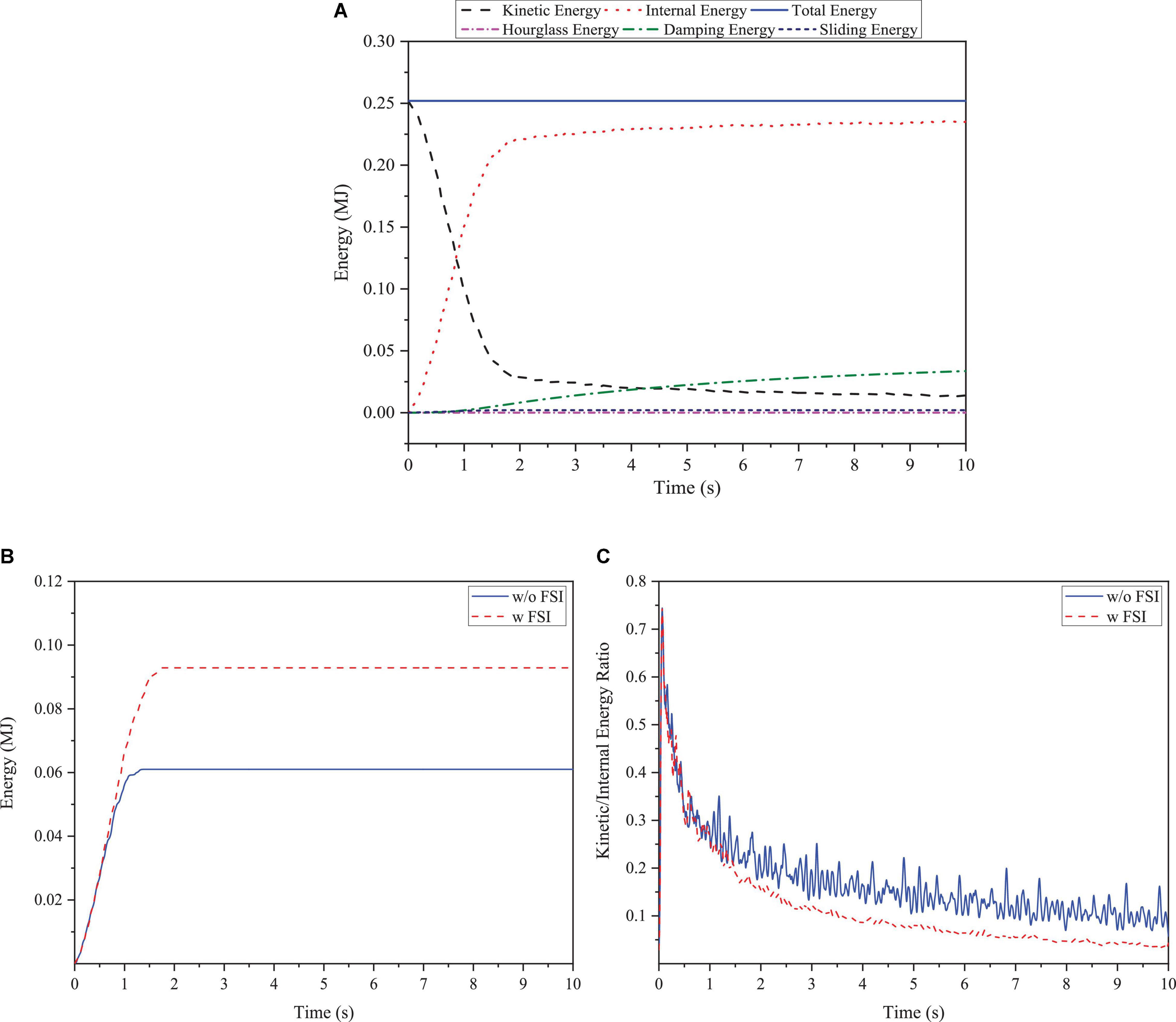
Figure 12. Sea ice and structure energy variation. (A) Energy variation of the collision coupling system; (B) Sea ice erosion energy variation, and (C) Ratio of structure kinetic energy to internal energy.
Except for the system energy of kinetic energy and internal energy, the interface slip energy and the hourglass energy generated by the explicit integral calculation are dissipated during the energy exchange process, as shown in Figure 12A. Interfacial slip energy should be kept at a small value to reduce the energy loss. Furthermore, the hourglass energy ratio derived in the numerical calculation is 0.037% (less than the requirement of 5%), indicating that the model, mesh density and calculation results are satisfactory.
The erosion energy of sea ice is shown in Figure 12B. With consideration of FSI, the erosion energy and the erosion failure effect of the sea ice are seen greater by comparing with the case without FSI. This indicates that fluids accelerate sea ice breaking and failure. Moreover, the ratio of the kinetic energy to the internal energy of the OWT supporting structure is shown in Figure 12C, in which smoother fluctuations and smaller energy are observed in the case with FSI coupling.
Conclusion
In this article, the interaction between sea ice and a NREL 5 MW monopile OWT is investigated based on ANSYS/LS-DYNA considering full SSI and FSI. Local- and global-coupled three-dimensional crushing during the collision process between the sea ice and the OWT structure are considered. The accuracy of the simulated ice force is first compared with DEM and current standards. Then, a complete dynamic collision process of sea ice and OWT is simulated using the proposed model, in which the effect of seawater is examined by coupling with and without FSI.
The main conclusions are given as follows:
(1) The simulated ice loading is a close representative of current standards and can produce a significant vibration response in the structure coupling with FSI.
The dynamic ice force on the flexible OWT can be calculated effectively and reasonably by the method presented in this study. The simulation results are consistent with the ice force calculated from ice force spectrum fitting method. Concurrently, this method can generally capture the main characteristics of the ice-OWTs interaction process with FSI. The ice-induced resonance is found to occur in the ice velocity range of 2.5–3.5 cm/s resulting in significant steady-state vibrations of the structure.
(2) Effects of fluid have to be considered in the dynamic analysis of ice-OWT interaction.
Fluid damping and the relative velocity of the sea ice-structure interaction are the main factors affecting the ice force. In the sea ice collision mode considered the initial velocity, fluid damping only produces the hysteresis of the ice force and has little effect on the ice force at the beginning of the collision. As the collision proceeds, the fluid accelerates the breaking of the sea ice, resulting in changing the ice force frequency, reducing the ice force amplitude and the mean value. However, the crushing failure mode and ice force variation trends of sea ice are generally not affected. Meanwhile, the FSI effect weakens the energy variation of the OWT structure, thus playing a certain protective role. In a word, the existence of the fluid affects the collision process and the ice crushing failure mode, which affects the ice force and the structure energy.
The results and analysis methods presented in this article can be applied to the assessment and design of the ice-resistance performance of OWTs. For further study, a refined meshing coupling with FSI can be accomplished by higher capability computing devices. Dynamic ice force model test and validation work can be carried out to obtain more reliable results. Meanwhile, the next segment of the research work will be focused on the “frequency locked” phenomenon of the structure caused by the ductile failure of sea ice.
Data Availability Statement
The raw data supporting the conclusions of this article will be made available by the authors, without undue reservation.
Author Contributions
WS: conceptualization. WS and YL: methodology. YL: investigation. WS, WW, SQ, and BW: writing—first draft preparation and writing and review and editing. SQ: visualization. WS and XL: supervision. WS, WW, and XL: set the objectives of the research, provided guidance for the research, and revised the manuscript. All authors contributed to the article and approved the submitted version.
Funding
The authors would like to acknowledge the support from the National Natural Science Foundation of China (Grant Nos. 52071058, 51939002, and 52071301). This study was also partially supported by the LiaoNing Revitalization Talents Program (XLYC1807208) and the Fundamental Research Funds for the Central University (DUT20ZD219).
Conflict of Interest
BW is employed by PowerChina Huadong Engineering Corporation Limited.
The remaining authors declare that the research was conducted in the absence of any commercial or financial relationships that could be construed as a potential conflict of interest.
Publisher’s Note
All claims expressed in this article are solely those of the authors and do not necessarily represent those of their affiliated organizations, or those of the publisher, the editors and the reviewers. Any product that may be evaluated in this article, or claim that may be made by its manufacturer, is not guaranteed or endorsed by the publisher.
References
Caraeni, D., Casseau, V., and Habashi, W. G. (2020). Fluid-structure interaction: extended-FEM approach to solidification. Finite Elem. Anal. Des. 177:103425. doi: 10.1016/j.finel.2020.103425
Daniel, H. (2011). “Simulation of ice action loads on off shore structures,” in Proceedings of the 12th European LS-DYNA Users Conference, Strasbourg.
Derradji-Aouat, A. (2005). “Explicit FEA and constitutive modelling of damage and fracture in polycrystalline ice-simulations of ice loads on structures,” in Proceedings of the 18th International Conference on Port and Ocean Engineering Under Arctic Conditions. (Potsdam, NY, USA: Clarkson University).
Herrnring, H., Kubiczek, J. M., and Ehlers, S. (2020). The ice extrusion test: a novel test setup for the investigation of ice-structure interaction – results and validation. Ships Offshore Struct. 15, S1–S9. doi: 10.1080/17445302.2020.1713437
Huang, L. F., and Tuhkuri, J. (2019). Ship resistance when operating in floating ice floes: a combined CFD&DEM approach. Mar. Struct. 74, 1–26. doi: 10.1016/j.marstruc.2020.102817
Huang, L. F., Ren, K., Li, M. H., Tukovic, Z., Cardiff, P., and Thomas, G. (2019). Fluid-structure interaction of a large ice sheet in waves. Ocean Eng. 182, 102–111. doi: 10.1016/j.oceaneng.2019.04.015
Huang, Z. G., and Zhang, G. Y. (2017). “Numerical simulation of shipboard-iceberg collision,” in Proceedings of the 8th International Conference on Computational Methods (ICCM). (Guilin, China: ICCM).
International Electrotechnical Commission [IEC] (2009). IEC 61400-3. Wind turbines, Part 3: design requirements for offshore wind turbines. Geneva: IEC.
International Organization for Standardization [ISO] (2010). ISO 19906. Petroleum and Natural Gas Industries-Arctic Offshore structures. ISO 19906. Geneva, Switzerland: International organization for standardization.
Jaakko, H., and Simo, R. (2017). Coupled-crushing analysis of a sea ice-wind turbine interaction - feasibility study of FAST simulation software. Ships Offshore Struct. 12, 1056–1063. doi: 10.1080/17445302.2017.1308782
Ji, S. Y., Di, S. C., Li, Z., and Bi, X. J. (2013). Discrete element numerical simulation of interaction between sea ice and vertical structures. Eng. Mech. 30, 463–469.
Jonkman, J. M. (2005). FAST user’s guide, Technical Report No. NREL/EL-500-38230. Golden, CO: National Renewable Energy Laboratory.
Kaimal, J. C., Wyngaard, J. C., Lzumi, Y., and Cote, O. R. (1972). Spectral characteristics of surface-layer turbulence. Q. J. R. Meteorol. Soc. 98, 563–589. doi: 10.1002/qj.49709841707
Kärnä, T., and Qu, Y. (2004). “A New Spectral Method for Modeling Dynamic Ice Actions,” in Proceedings of the 23th International Conference on Offshore Mechanics and Arctic Engineering. (Vancouver, Canada: ASME). doi: 10.1115/OMAE2004-51360
Kuutti, J., Kolari, K., and Marjavaara, P. (2013). Simulation of ice crushing experiments with cohesive surface methodology. Cold Reg. Sci. Technol. 92, 17–28. doi: 10.1016/j.coldregions.2013.03.008
Liu, L., and Ji, S. Y. (2018). Ice load on floating structure simulated with dilated polyhedral discrete element method in broken ice field. Appl. Ocean Res. 75, 53–65. doi: 10.1016/j.apor.2018.02.022
Masterson, D. M., and Frederking, R. M. W. (1993). Local contact pressures in ship/ice and structure/ice interactions. Cold Reg. Sci. Technol. 21, 169–185. doi: 10.1016/0165-232X(93)90005-S
Ren, Y., Vengatesan, V., and Shi, W. (2022). Dynamic Analysis of a Multi-column TLP Floating Offshore Wind Turbine with Tendon Failure Scenarios. Ocean Eng. 245:110472. doi: 10.1016/j.oceaneng.2021.110472
Seeking, R. J., Verma, A. S., Li, Y., Teuwen, J. J. E., and Jiang, Z. (2021). Offshore wind turbine operations and maintenance: a state-of-the-art review. Renew. Sustain. Energ. Rev. 144:110886. doi: 10.1016/j.rser.2021.110886
Shi, W., Tan, X., Gao, Z., and Moan, T. (2016). Numerical study of ice-induced loads and responses of a monopile-type offshore wind turbine in parked and operating conditions. Cold Reg. Sci. Technol. 123, 121–139. doi: 10.1016/j.coldregions.2015.12.007
Song, M., Shi, W., Ren, Z. R., and Zhou, L. (2019). Numerical Study of the Interaction between Level Ice and Wind Turbine Tower for Estimation of Ice Crushing Loads on Structure. J. Mar. Sci. Eng. 7, 1–23. doi: 10.3390/jmse7120439
Sun, X. J., Huang, D. G., and Wu, G. Q. (2012). The current state of offshore wind energy technology development. Energy 41, 298–312. doi: 10.1016/j.energy.2012.02.054
Suominen, M., Kujala, P., Romanoff, J., and Remes, H. (2017). Influence of load length on short-term ice load statistics in full-scale. Mar. Struct. 52, 153–172. doi: 10.1016/j.marstruc.2016.12.006
Tang, Y., Shi, W., Ning, D., You, J., and Michailides, C. (2020). Effects of Spilling and Plunging Type Breaking Waves Acting on Large Monopile Offshore Wind Turbines. Front. Mar. Sci. 7:427. doi: 10.3389/fmars.2020.00427
Wang, Y., Shi, W., Michailides, C., Wan, L., Kim, H., and Li, X. (2022). “WEC shape effect on the motion response and power performance of a combined wind-wave energy converter,” in Ocean Engineering.
Yang, B. Y., Sun, Z., Zhang, G. Y., Wang, Q. K., Zong, Z., and Li, Z. J. (2021). Numerical estimation of ship resistance in broken ice and investigation on the effect of floe geometry. Mar. Struct. 75:102867. doi: 10.1016/j.marstruc.2020.102867
Ye, K. H., Li, C., Yang, Y., Zhang, W. F., and Xu, Z. F. (2019). Research on influence of ice-induced vibration on offshore wind turbines. J. Renew. Sustain. Energ. 11:033301. doi: 10.1063/1.5079302
Yue, Q. J., and Bi, X. J. (2000). Ice induced jacket structure vibration. J. Cold Reg. Eng. 14, 81–92. doi: 10.1061/(ASCE)0887-381X(2000)14:2(81)
Zhang, D. Y., Wang, G., and Yue, Q. J. (2018). Evaluation of ice-induced fatigue life for a vertical offshore structure in the Bohai Sea. Cold Reg. Sci. Technol. 154, 103–110. doi: 10.1016/j.coldregions.2018.05.012
Zhang, X. (2002). Steady-state vibration of ice excitation vertical structures. Ph.D. thesis. Dalian: Dalian University of Technology
Zhao, Z., Shi, W., Wang, W., Qi, S., and Li, X. (2021). Dynamic analysis of a novel semi-submersible platform for a 10 MW wind turbine in intermediate water depth. Ocean Eng. 237:109688. doi: 10.1016/j.oceaneng.2021.109688
Zhou, L., Ding, S., Song, M., Gao, J., and Shi, W. (2019). A Simulation of Non-Simultaneous Ice Crushing Force for Wind Turbine Towers with Large Slopes. Energies 12, 2608–2620. doi: 10.3390/en12132608
Keywords: ice-structure interaction, monopile offshore wind turbine, non-linear finite element modeling, fluid-structure interaction, collision model
Citation: Liu Y, Shi W, Wang W, Li X, Qi S and Wang B (2022) Dynamic Analysis of Monopile-Type Offshore Wind Turbine Under Sea Ice Coupling With Fluid-Structure Interaction. Front. Mar. Sci. 9:839897. doi: 10.3389/fmars.2022.839897
Received: 20 December 2021; Accepted: 14 February 2022;
Published: 11 March 2022.
Edited by:
Vasant Annasaheb Matsagar, Indian Institute of Technology Delhi, IndiaReviewed by:
Bang-Fuh Chen, National Sun Yat-sen University, TaiwanDimitris Stagonas, University of Cyprus, Cyprus
Copyright © 2022 Liu, Shi, Wang, Li, Qi and Wang. This is an open-access article distributed under the terms of the Creative Commons Attribution License (CC BY). The use, distribution or reproduction in other forums is permitted, provided the original author(s) and the copyright owner(s) are credited and that the original publication in this journal is cited, in accordance with accepted academic practice. No use, distribution or reproduction is permitted which does not comply with these terms.
*Correspondence: Wei Shi, d2Vpc2hpQGRsdXQuZWR1LmNu; Xin Li, bGl4aW5AZGx1dC5lZHUuY24=