 Dan Novy1,2,3†*
 Lui Kawasumi4†
 Jon Ferguson1Margaret Sullivan5
 Peter Bell6
 Jennifer S. Chow1,2
 João Borges de Sousa7Kat A. Cantner2,8Benjamin Woodward9
 Allan Adams10‡
 Katherine L.C. Bell1,2‡
- 1MIT Media Lab, Cambridge, MA, United States
- 2Ocean Discovery League, Saunderstown, RI, United States
- 3University of Nebraska–Lincoln, Johnny Carson Center for Emerging Media Arts, Lincoln, NE, United States
- 4Boston University, Department of Mechanical Engineering, Boston, MA, United States
- 5University of California San Diego, Scripps Institution of Oceanography, San Diego, CA, United States
- 6Cornell University, Department of Computer Science , Ithaca, NY, United States
- 7University of Porto, Laboratório de Sistemas e Tecnologias Subaquáticas, Porto, Portugal
- 8Continental Scientific Drilling Facility, School of Earth and Environmental Sciences, Minneapolis, MN, United States
- 9CVision AI, Medford, MA, United States
- 10Oceanic Labs Research Foundation, Cambridge, MA, United States
The deep sea (>200 m) is vast, covering 92.6% of the seafloor and largely unexplored. Imaging and sensor platforms capable of surviving the immense pressures at these depths are expensive and often engineered by individuals and institutions in affluent countries as unique, monolithic vehicles that require significant expertise and investment to build, operate, and maintain. Maka Niu was co-designed with a global community of deep-sea researchers. It is a low-cost, modular imaging and sensor platform that leverages off-the-shelf commodity hardware along with the efficiencies of mass production to decrease the price per unit and allow more communities to explore previously unseen regions of the deep ocean. Maka Niu combines a Raspberry Pi single-board computer, a Pi Camera Module V2, and a novel pressure housing and viewport combination capable of withstanding 1,500 m water depth. Other modules, including high-lumen LEDs, can be engineered to use the same battery charging and control system and form factor, allowing for an ever-increasing number of capabilities to be added to the system. After deployment, imagery and sensor data are wirelessly uploaded to Tator, an integrated media management and machine learning backend for automated analysis and classification. Maka Niu’s mobile mission programming and data management systems are designed to be user-friendly. Here, Maka Niu is described in detail along with data and imagery recorded from deployments around the world.
1. Introduction
The deep sea, which lies below 200 m and covers 92.6% of the seafloor (Eakins and Sharman, 2012), is vast and largely unexplored. This makes imaging and sensor platforms that can withstand the incredible pressures at these depths ubiquitous and mandatory elements of deep-ocean exploration, including human occupied vehicles (HOVs), tow sleds, remotely operated vehicles (ROVs), autonomous underwater vehicles (AUVs), and benthic landers (Phillips et al., 2019; Sun et al., 2021). Pressure housings for these platforms, traditionally made from aluminum or titanium, are often custom-fabricated for a single vehicle or instrument. Exotic materials, specialized subsystems, and one-off fabrication keep the cost of deep-ocean imaging and sensing extremely high. These cost restrictions limit accessibility and restrict deployment opportunities to those with enough operating capital to bear the cost of building and maintaining these deep-sea platforms. However, a growing community of ocean scientists, particularly in regions of the world that have been historically ignored or undervalued, need the exploration capabilities that a low-cost and mass-producible imaging system would provide (Bell, Chow, et al., 2022).
While recent attention has been paid to lowering the cost of deep sea exploration and research systems, there is much room for further improvement (Hardy et al., 2013; Cazenave et al., 2014; Phillips et al., 2019; Giddens et al., 2021). Current advances in the mass production of inexpensive but powerful single-board computers, open-source operating systems, 3D printing, and digital design and fabrication offer opportunities to increase the overall capacity for deep-ocean imaging and data acquisition (Jolles, 2021). At the same time, mission programming and sensor data management have traditionally been the purview of control systems specialists and dedicated data scientists. However, a growing field of open-source operating systems, lightweight web servers, commodity Wi-Fi capabilities, and programming frameworks enables the creation of simplified user interfaces and data handling workflows, which can be used by non-experts and thereby increase the overall capacity of deep-ocean exploration and observation (Amon et al., 2022).
But data acquisition, by itself, only partially completes the goal of scientific observation. Once deep-ocean imagery is recorded, current workflows involve human observation and annotation, which require unsustainable investments of time or restrict inspection to only select data samples. Tools currently under development integrate machine learning to automate the ingestion and inspection of the collected imagery and eventually the visualization of the collected data.
In this paper, we detail and provide open source access to the mechanical, electrical, and digital control design for the Maka Niu system, including the internal 3D-printed dry chassis; the battery management and sealed inductive charging system; and the Raspberry Pi camera and control subsystems. While the use of a Raspberry Pi camera for low-cost underwater imaging is not unique, few of these systems are designed for nor capable of reaching 1,500 m depth or more. (Almero et al., 2021; Bergshoeff et al., 2016; Marini et al., 2013; Marini et al., 2018; Marini et al., 2022). We also describe additional modules that are currently being engineered and suggest the construction of future modules to expand overall system capabilities. This work has the potential to lower the cost of deep-ocean exploration by orders of magnitude, across many sectors and communities of ocean scientists and enthusiasts.
2. Methods
Maka Niu was conceived in February 2020 as an educational tool in collaboration with Nainoa Thompson, Lehua Kamalu, Chris Blake, Sonja Swenson Rogers, and Noelani Kamalu of the Polynesian Voyaging Society. The system was named Maka Niu, or “coconut eye” in Hawaiian, in tribute to the initial concept of using coconuts as flotation devices to deploy the low-cost imaging systems with students from Kamehameha Schools in Honolulu, Hawai’i. Due to COVID-19, the engineering design process took longer than anticipated, allowing us to incorporate learnings from a series of co-design interviews that were carried out with twenty marine professionals from ten countries in July–August 2020 (Bell, Chow, et al., 2022). While originally envisioned as an imaging and sensing system for educational use, the utility of the system for a broader range of marine users quickly became apparent throughout the interview and engineering design process.
The co-design interviews provided requirements and recommendations for sensors and capabilities, as well as considerations for deployment scenarios that would make the system more useful and accessible for a wider range of users (Supplementary Material A). In the design and engineering process, we took into account as many of the design requirements and considerations as possible to incorporate into the Maka Niu system, particularly temperature, depth, imaging, and easy access to video and data, as well as GPS, ease of use, and easily programmable missions (Bell, Chow, et al., 2022). Once the systems were built, thirteen were shipped to be tested by interviewees in eleven locations around the world. A full description of the participatory design study that informed this work can be found in Bell, Chow, et al., 2022.
The research, design, development, and initial deployment of the Maka Niu platform happened entirely during the COVID-19 pandemic. Access to the usual tools, facilities, and resources was at times nonexistent. However, those limitations also prove the value of a system such as the Maka Niu, as it was developed largely in the homes of the distributed team. Using off-the-shelf parts wherever possible, 3D printing both at home and outsourced, and working with fast and low-cost circuit fabricators—all make it possible to build tools with far-reaching impact, while minimizing cost and the requirement for specialty equipment.
All mechanical, electrical, and software components of the Maka Niu design are made available, and maintained, through github repositories linked in the appendix.
3. Results
3.1. Mechanical design
The main mechanical components of the Maka Niu system are the pressure-rated housing, the dry chassis, exterior controls, deployment hardware, and the wireless charging cradle (Figure 1).
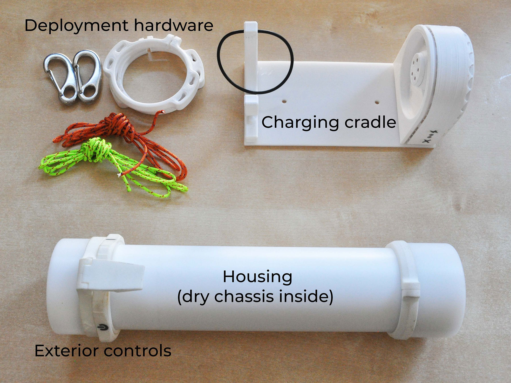
Figure 1 The mechanical components of the Maka Niu system include the pressure-rated housing, the dry chassis, the exterior controls, the deployment hardware, and the wireless charging cradle.
Housing: The pressure rated housing of the Maka Niu consists of several machined Delrin components. While this is admittedly an expensive manufacturing process, tight tolerances and resilient material are necessary to achieve the system’s 1,500 m depth capability. To reduce costs as much as possible, the design has been minimized to just five machined components: a stock tube with externally threaded ends, a rear endcap, a small cap for the wireless power coil that fits into the endcap, and two hold-downs. The optical port is a simple acrylic disk, 12 mm thick. The optical port and the rear endcap are sealed at the ends of the tube with face seal o-rings, and are held firmly in place by the two hold-downs. The internal space is 40 mm in diameter and 220 mm long. The components are not complex, and none require internal undercuts, which makes it possible to reproduce them using reasonably accessible machining tools.
The housing maintains atmospheric pressure inside with no need to pull a vacuum. The 1,500 m depth-rated housing has been pressure tested in a lab setting at the Woods Hole Oceanographic Institution in Woods Hole, Massachusetts. Test details are discussed in section 3.6.
Dry chassis: The internal 3D-printed dry chassis is a modular design that accommodates a variety of power, computational, and/or sensing needs. It has been designed with quick-locking mated interfaces for fast assembly or reconfiguration. The current standard camera configuration consists of three connecting subsystems: the battery subsystem, the compute subsystem, and the camera subsystem (Figure 2). As user needs change, new subsystems can be designed and swapped in to use other components. For instance, as less-expensive, higher-quality cameras become available, the camera subsystem can be revised to take advantage of these upgraded cameras, while keeping the current battery and compute subsystems.
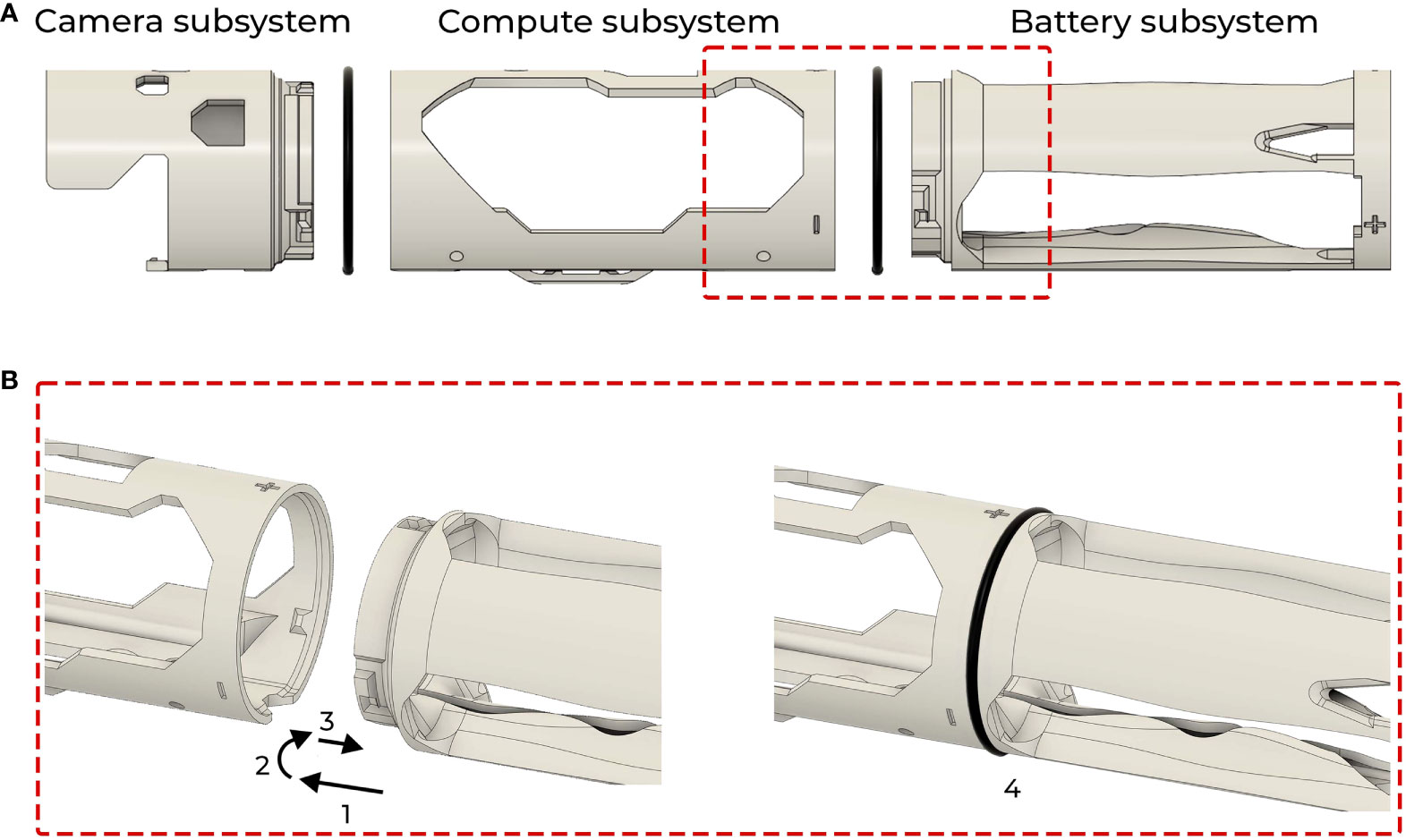
Figure 2 (A) The dry chassis consists of three modules with distinct functions. (B) Modules connect through a quick four step process: insert one module into another, twist, pull away, and finally place an O-ring in the gap. The O-ring prevents reversal of the described motion, while also functioning as a bumper between the chassis and the housing.
Exterior Controls: The exterior of the camera has a 3D-printed control interface that consists of a six-position rotating control ring and a levered push button. As with wireless charging, the controls have been designed to function without penetrators to minimize risk to housing integrity. The push button and the control ring each hold a neodymium magnet, the position of which is tracked by hall-effect sensors inside the housing. See section 3.2 Control Interface Sensing for details regarding the electrical design. The six positions of the control ring correspond to one power OFF state, and five ON state modes (Wi-Fi, still capture, video capture, Mission 1, and Mission 2). The push button enables user input in the ON states, such as beginning and ending video capture. To facilitate use as a dive camera, the interface is friendly to one-handed use (Figure 3).
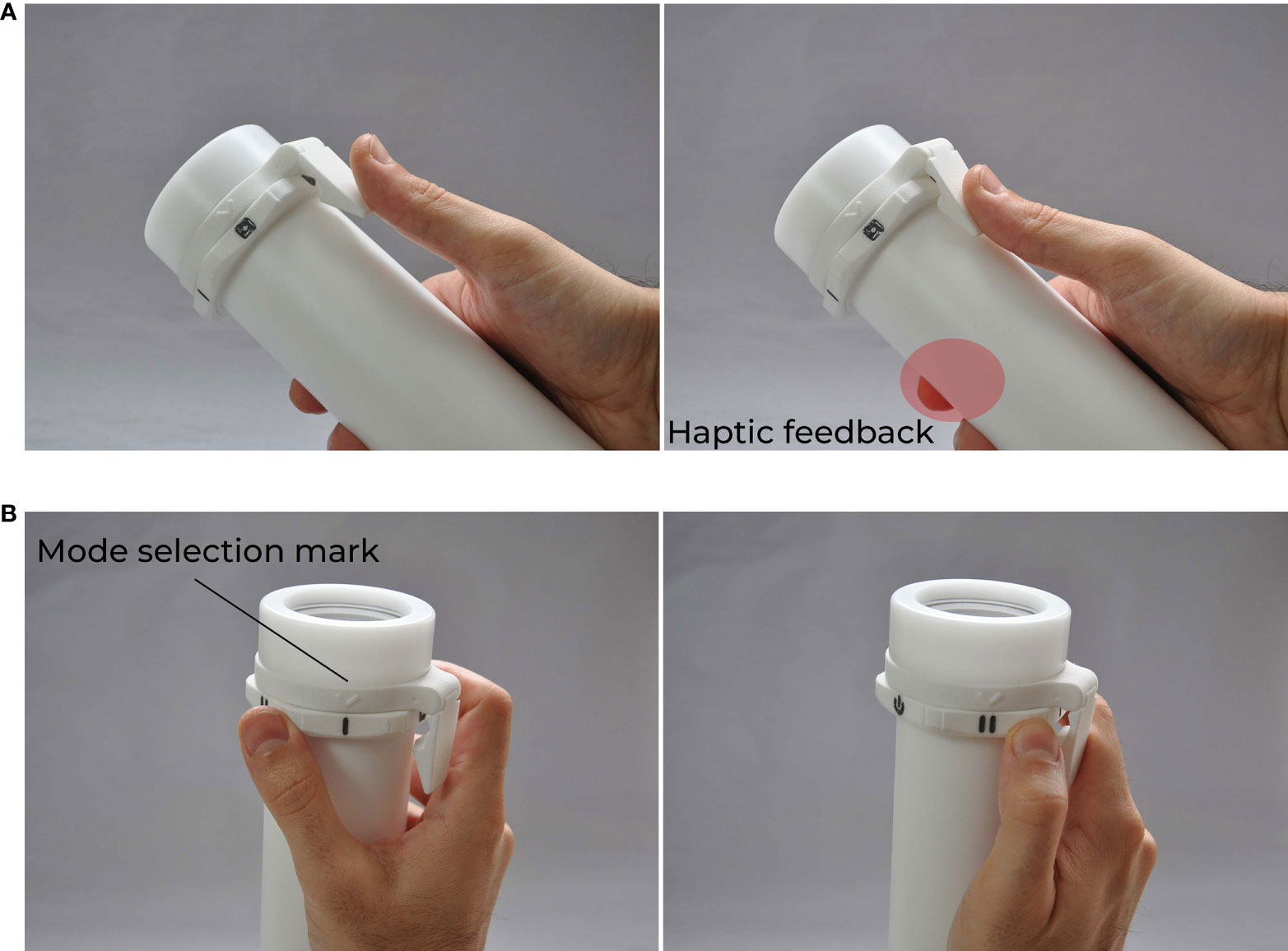
Figure 3 (A) The push button is used for specific operations, such as starting and stopping video capture, or taking a still image. These actions also initiate haptic feedback which can be felt by a user holding the unit. (B) The control ring can be operated with one hand to select modes. Current mode is indicated by the mode selection mark.
Deployment Hardware: A pair of clamps with quick grip slots, a pair of 1.8 mm Spyderline Micro Dyneema Braid lines, and a pair of stainless steel carabiners are provided to users to facilitate deployment of Maka Niu, whether just below the water surface or just above the sea floor. Users are encouraged to source weights and flotation locally, but the hardware necessary to connect those components to the camera is provided (Figure 4). When not under tension, the lines can slide through the quick-grip slots, so the deployment angle is easy to adjust. Once the preferred angle is set, pulling on the lines locks them in place, and during deployment, tension in the lines from the float and the weight ensures that the lines don’t slip. While the angle is set by the upper line, the weight hanging on the lower line slides freely. Regardless of the set angle, the pull of the weight is evenly distributed to both ends of the camera. This reduces bobbing and jerking of the camera in the dynamic underwater environment, and leads to steadier video capture.
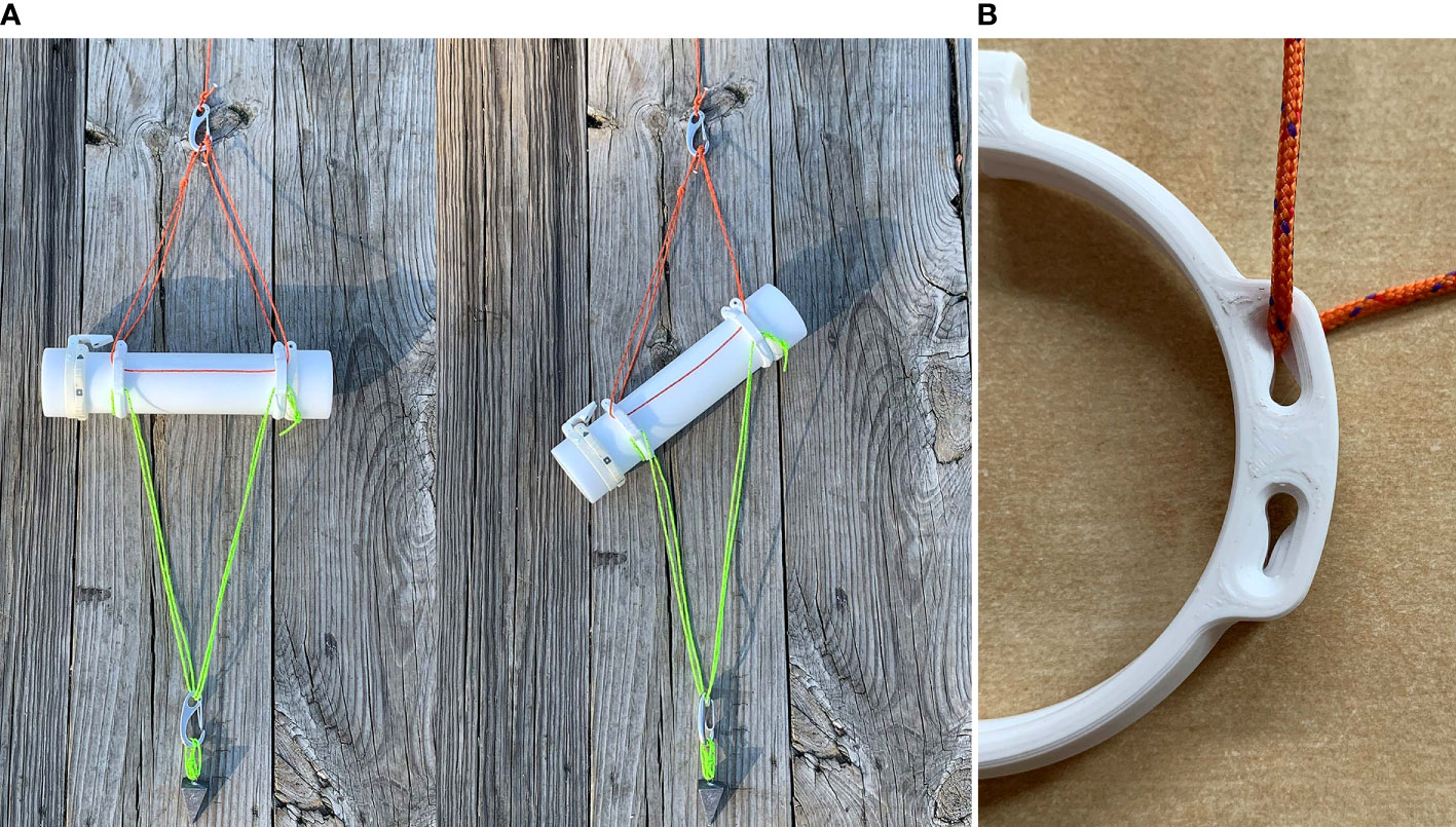
Figure 4 (A) The deployment angle of the camera can be adjusted by slipping cords to the desired position. (B) Quick-grip slots lock cords in place when they are under tension.
Charging Cradle: The body of the cradle consists of a hard plastic mounting plate and 3D-printed housing for the charger circuitry. The design of the cradle takes into account motion during at-sea deployments, as well as the need to manage heat generated by the wireless charging system. The cradle has mounting holes to enable installation to a wall or counter, and a strap is provided to lock the camera into the charger during high seas.
3.2. Electrical design
The electrical components of Maka Niu include the wireless power system, battery pack, computer, camera, sensors, control interface sensing, and feedback interface (Figure 5).
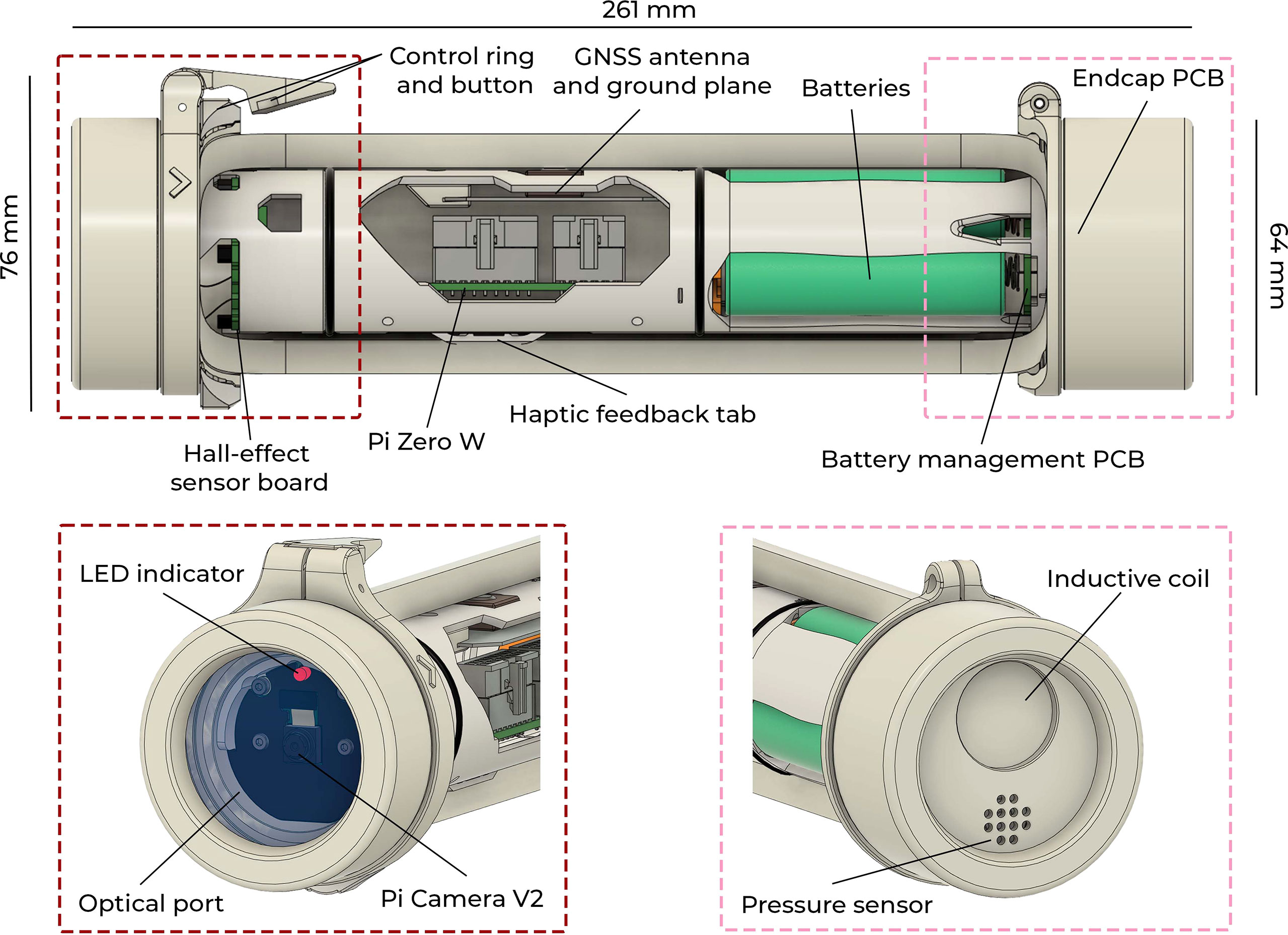
Figure 5 A partial cutaway of the housing exposes the dry chassis and the electrical components within. At the front are the optical port, the Raspberry Pi Camera Module and an LED indicator. At the rear are the charging port and the pressure sensor.
Wireless Power: Maka Niu is charged wirelessly using inductive charging. While use of this technology is unusual in marine research, and increases charging time, it has a key benefit; robustness in non-expert hands. By avoiding wet connectors, exposed metal, and sealed screw caps, inductive charging eliminates concerns that users will forget to replace a cap, damage threads over time, or compromise seals with debris. Charging a Maka Niu camera is akin to charging an electric toothbrush.
Inside the rear endcap of Maka Niu are an inductive coil and a custom printed circuit board, which primarily functions as a wireless power receiver. The design is based on the 15 W wireless power development kit 760308MP2, by Würth Elektronik and Renesas Electronics. The kit provides the groundwork for selecting transmitter and receiver coil pairs, and tuning circuitry to achieve inductive power transmission. The Endcap PCB also has a number of additional features; beyond the inductive charge controller, it contains chips for global position and 9-axis motion sensing.
The charging cradle employs a custom wireless power transmitter circuit, also based on the 15 W development kit. To manage heat generated in the coils, charge rate is limited and a cooling fan blows air over a heatsink behind the transmitter coil. The approximate time to fully charge a depleted Maka Niu battery system is eight to nine hours, making it effectively an overnight process. LED indicators on the charger display its current status, such as charging, charged, and fault.
Battery Pack: The battery pack consists of three 18650 size batteries and a custom battery management system (BMS). The particular batteries used are LG-MJ1, Li-ion batteries with 3500 mAh capacity. They are wired in series for a nominal voltage of 11.1 V, and a maximum possible charge voltage of 12.6 V. In the current design, the charging hardware typically charges the batteries up to 12 V, and the Maka Niu software initiates system shutdown when the voltage drops below 9 V. The current hardware, and software design are not yet optimized for extended battery life, but on a full charge, Maka Niu can record approximately eighteen hours of continuous video. Details of battery testing are discussed in section 3.6, and methods of optimizing for longer deployments are discussed in section 4.3.
Computer: For computation, Maka Niu uses the Pi Zero W by the Raspberry Pi Foundation. It is a low-cost, single-board computer with built-in Wi-Fi and Bluetooth. It is also equipped with a connector to interface directly with the Pi Camera Module V2. On October 28, 2021, a new version—the Pi Zero 2 W with a multi-core chipset—was released, and development and testing is underway to upgrade to this new board.
Camera: The onboard optical camera is a Pi Camera Module V2. With an 8 megapixel sensor, it allows for 3280x2464 stills and 1080p video at 30 fps with a horizontal field of view of 62.2° and a vertical field of view of 48.8° (https://www.raspberrypi.org/documentation/hardware/camera/). The camera is designed for, and well-supported by, the Raspberry Pi community, enabling quick integration and development. While higher-resolution camera modules are available for the Raspberry Pi platform, the V2 module was chosen for its small physical footprint and low cost, which helps to decrease the total cost per unit.
Sensors: Maka Niu is built with a number of additional sensors to create a powerful standalone platform. The unit is equipped with a global navigation satellite system (GNSS), 9-axis motion tracking, and exterior pressure and temperature sensing. Sensor data is logged every second so that the images and videos captured by the camera have accompanying metadata on global coordinates, orientation, and the depth and temperature of the environment.
Geolocative coordinates of all sampled data, especially imagery, is essential to scientific analysis. To determine coordinates, Maka Niu uses the GNSS receiver XM1110 by Sierra Wireless. This receiver is built into the Endcap PCB, and is coupled with an active ceramic patch antenna. The receiver takes advantage of multiple families of satellites—GPS, SBAS and QZSS—and has a 3 m radius of accuracy with 50% Circular Error Probable, according to the manufacturer’s specifications.
With access to an open sky, Maka Niu typically acquires satellite data to determine current coordinates and UTC time within five minutes. Once acquired, the UTC time is maintained locally. The GNSS receiver is therefore used as a real-time clock to set timestamps for all of the camera captures and sensor data. Frame-accurate timestamps and GPS localizations are necessary inputs to the Tator and FathomNet machine learning annotation and classification platforms discussed in Section 3.3. GPS coordinate metadata is used specifically for search, sort, annotation, classification and eventually for output data visualization capabilities.
Understandably, Maka Niu cannot receive updated coordinates while underwater. Therefore, users are instructed to power on the Maka Niu above water before each deployment and wait for it to acquire its location, as indicated by a flashing green light. The location will then update every second until the Maka Niu is submerged. When the camera captures an image or a video underwater, the last known position and time are recorded in the metadata. This allows the system to provide an associated location with each capture, along with a measure of uncertainty.
Centered on the Endcap PCB is a 9-axis motion sensor IC, which tracks acceleration, rotation, and magnetic fields in three axes each. This data can be used to approximate Maka Niu’s tilt and orientation at the time of image or video capture. The Endcap PCB also connects to the pressure sensor 7LD by Keller, which has an absolute pressure rating of up to 200 bar (~2,000 m). It provides external pressure and temperature data, allowing the approximation of system depth at any time from the pressure values.
Control Interface Sensing: Maka Niu is controlled with a pair of magnets exterior to the sealed housing, one in the mode control ring and the other in the push button (Figure 3). To sense the position of the ring and button presses, inside the housing is a ring-shaped, Hall-Effect PCB with a total of seven hall-effect sensors facing radially outward. Six of the sensors are oriented to sense the inward-facing south pole of the magnet in the control ring, and one is oriented to sense the inward-facing north pole of the levered push button. This ensures that the control ring and the push button operate independently and do not cross-trigger, despite their close proximity. The control interface components are the only mechanical moving parts of the Maka Niu. Critically, the parts do not penetrate the housing, and so even if they wear or break, there is no risk to the integrity of the housing. They can also be replaced without opening the housing.
Feedback Interface: There are two feedback interfaces available to the user: optical and haptic. The Hall-Effect PCB has a red-green LED indicator that is visible through the front optical port. The LED provides information about the state of the Maka Niu, such as what mode it is in, whether it is capturing video, its remaining battery life, and whether the camera has a satellite connection to establish geospatial position. For widest accessibility, flash patterns are also used so that users can recognize all status information without relying on the color of the LED.
A small vibrating motor is mounted in contact with the interior wall of the housing. Haptic feedback is provided to make it easier to use the Maka Niu as a dive camera, with vibrations used to confirm button presses and control ring mode changes.
3.3. Software design
Python: The central program running on the Maka Niu is a Python daemon that handles all of the communication with the device’s peripheral hardware. It controls the camera indirectly using shell commands; a separate program, RPi-Cam-Web-Interface, receives those commands and directly operates the Pi Camera Module.
The Python daemon determines which mode is currently selected by reading the state of the six hall-effect sensors to ascertain which one has been activated by the magnet on the control ring. A degree of software filtering avoids noise in the determination of the set mode, while delays ensure that modes can be skipped over by rotating through them quickly with the dial. In the daemon, different sections of code are run depending on the active mode.
The Python daemon checks all available sensors at a rate of 1 Hz. Every time an image is captured or a video is recorded using the push button of the camera, or whenever the dial is in one of the mission modes, the script creates a sensor log file with the same file name as the capture or the mission, and begins to log sensor data into that file (Figure 6). The current state of the ring is also reported in a separate status file for other programs to monitor and act on. Each line begins with a four-letter code representing the source sensor. This data format was modeled on that used by ROVs Hercules and Argus and developed by Jon Howland (Martin, 2010). The Maka Niu sensor data format is as follows:
•GNSS: provides both current global coordinates and UTC date and time, which the Python program notes and uses for all other data timestamps.
•GNS2: provides last known global coordinates and time since those coordinates were updated
•BATT: provides battery voltage; if this drops below 9 V, the Maka Niu unit initiates shutdown.
•IMUN: provides data from the inertial measurement unit: acceleration, rate of rotation, and magnetic field strength in three principal axes. This data can be used to approximate the orientation of the camera
•KELL: provides pressure, depth, and external temperature from the Keller sensor.

Figure 6 Maka Niu logs metadata for every image and for every second of video or duration of a mission. This particular log reveals that on September 29, 2021, at 1AM UTC time, the camera was in the Santa Monica Basin, it was nearly fully charged, it was oriented horizontally at the surface, and the temperature in its environment was 25C.
The first number on each line of the sensor log is the Pi’s UNIX monotonic clock, which gives the number of microseconds since boot. The second and third numbers are the UTC date and time. The monotonic clock gives absolute time differences between measurement readings and is isolated from any changes to the UTC clock, which is sometimes adjusted by the GNSS receiver. All remaining numbers on each line are data from the sensor indicated by the initial four-letter code.
Note that the Keller sensor itself provides only pressure and temperature values; depth is calculated in the Python script using the pressure and offsets. The sensor is rated by the manufacturer with a total error band of 0.5%, and a noise floor maximum of 0.015% from the full-scale measurement. The direction of the error is fixed. Since the pressure sensor is rated for up to 2000 m, at any depth, a given sensor may have a constant depth error of up to 10 m. This error differs from unit to unit. At shallow depths, such an error makes depth data wholly unuseable. To compensate, whenever Maka Niu has an active GPS signal, indicating that it is out of the water and consequently at local atmospheric pressure, the Python script calculates a running average of the presumed depth based purely on the absolute pressure value from the Keller sensor. This number is saved in flash memory and kept as an offset to determine an adjusted depth value of zero meters at the surface. As soon as Maka Niu is submerged, it loses the GPS signal, so the program stops updating the offset, but continues to use it to estimate adjusted depth. By taking advantage of Maka Niu’s GPS capability, each unit is effectively able to auto-calibrate itself for fabrication tolerances of the pressure sensor, as well as for local atmospheric pressure, be that at sea level or at a high altitude lake. The method has reduced the shallow water depth error down to sensor noise which is ±0.3 m.
Coconut: When the control dial is turned to either of the mission modes, the Python script sets a flag that signals the Coconut mission management daemon to operate. Coconut is the programmable mission engine that allows scripted, intelligent, reactive, sensor-based mission planning and execution. It is written in Node.js and runs in the background at boot time. Coconut monitors the ring status file and consumes and parses the sensor log file in real-time and uses the data to step through mission sequences. During one of two mission modes, the Coconut mission engine operates as a state machine, using the sensor log data to determine which state the control system should be in according to a pre-programmed mission file. Mission files are simple text-based JavaScript files that describe a series of sequential actions or loops based on sensor data input.
Maka Niu currently ships with two default mission files. Mission 1 initiates video capture in a user-determined capture interval when the unit descends below a user-determined depth; Mission 2 begins time-lapse capture of still frames at a user-determined rate upon mission start.
Missions can be programmed visually using a procedural, graph-based interface accessed through a browser and served from a Node.js Express-based web app (Figure 7). The mission programming graphical user interface (GUI) is based on GoJS, a framework for rapidly building interactive diagrams. Missions can be laid out as a series of blocks or nodes with input values from sensors in real time, such as time or depth used as triggers to progress the mission engine into its next state. Since Maka Niu can act as an access point for a user’s smartphone or laptop, missions can be edited in the field immediately prior to deployment if necessary, using a touchscreen on a mobile device or through a standard laptop. Missions can also be edited through the GUI while the device is in client mode on the user’s home network and are automatically saved and stored for deployment. GoJS allows for desired trigger values and conditionals to be directly edited and adjusted for execution by the Coconut mission engine.
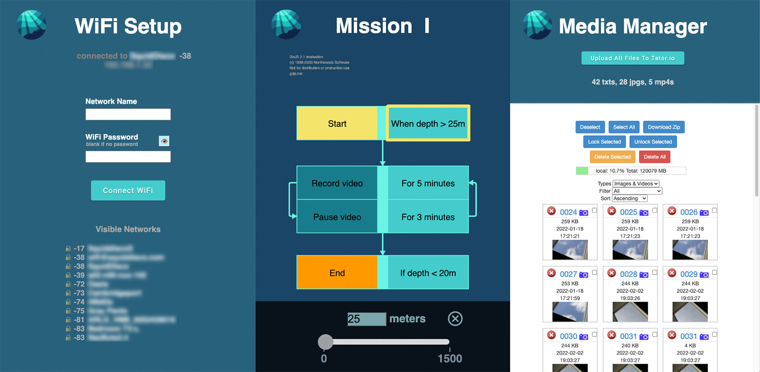
Figure 7 The Node.js Express web-based mission programming graphical user interface (GUI).
A user may also access the mission files via SSH over the device’s natively served Wi-Fi access point or over its Wi-Fi as a client on the user’s home network. Mission files can be written or modified using any text editor available to the Linux operating system. The mission engine has full access to the current state of all sensors and can use this data to make control loop decisions, such as waiting for a combination of specific conditions to be met and then capturing video or still images.
Being able to program missions through an easy, node-based, drag-and-drop interface is one of the key functionalities that makes Maka Niu so accessible. While a power user can create and edit missions using SSH and the command line interface, graphical programming allows newcomers and non-experts to quickly adjust existing missions, and to easily create custom missions, to suit their operational needs.
Dual Wi-Fi Modes: While out of the water, Maka Niu offers connections to its mission programming environment, media management environment, and all sensor and recorded data communications through a dual-mode configuration that provides network access directly to the device through its native Wi-Fi. In access point (AP) mode, the device offers an access point for device-to-device communication. The main purpose of AP mode is to offer an easy-to-use setup tool to configure the device to operate in client mode on a more robust Wi-Fi network. After connecting a smartphone or laptop to Maka Niu as an access point, a simple configuration page allows a user to input the SSID and password combination of a station mode network. These credentials are maintained from session to session and only need to be entered once while in access point mode. Unless the user intends to create or edit missions or sort and delete media while in the field, the access point mode need not be used again except for diagnostic purposes. In client mode, as a device on a user’s main Wi-Fi network, the device gains full access to the internet to upload data for storage, analysis, and visualization. This dual-mode configuration allows for robust and redundant communication, ensuring at least one channel of communication with, and control of, the device is available at all times. During missions, while the unit is submerged, the Wi-Fi system is disabled to increase battery life and mission duration.
VPN and Rover: In addition to accessing the device locally, Maka Niu is also configured to maintain a VPN connection back to a central server. Using OpenVPN clients on the devices and the OpenVPN server on a central machine, units can be monitored, debugged, and upgraded wherever they have an internet connection. Once connected, devices can be logged into via SSH and the Coconut web interface can be accessed. Software fixes and updates can be pulled down using the Git software configuration management system, and system log files and mission data files can be examined and downloaded. This capability has enabled the engineering team in Cambridge, Massachusetts, to remotely update the software of several of the thirteen Maka Niu cameras around the world.
Rover is an easy-to-use web dashboard written in Node.js and Express that lists all currently internet-connected Maka Niu systems on a central server. Connecting to a remote system in the field can be done with only a few clicks. Access to the Rover interface and the connected Maka Niu devices is enabled by separate OpenVPN client keys issued to each authorized user. The keys are used to establish a VPN connection back to the central server granting access to the web interface and to the Maka Niu devices. Individual keys can be revoked at any time when access is no longer necessary.
Imaging system: The imaging pipeline aboard Maka Niu allows for video capture at any resolution and frame rate, up to and including 1920x1080 at 30 fps. Still images can be taken at a maximum of 3280x2464, individually or as part of a sequential time lapse. Time-lapse stills can then be uploaded and converted for viewing and analysis as a video. Due to system memory limitations, time-lapse images at full resolution should currently be converted using a different device after upload so as not to overload the system. Lower resolution image sequences can be converted to video on Maka Niu, depending on the number of images.
The imaging pipeline incorporates the open-source RPi Cam Web Interface (RPiCWI) community project. RPiCWI is a highly configurable and extendable interface to the Raspberry Pi Camera Module. It is accessible on any browser and operates on a combination of PHP and Linux system-level shell scripting. It allows complete command line configuration and control of the entire imaging system, and also provides a browser accessible webpage for viewing, sorting, converting, deleting, and uploading all imagery taken during deployment.
At its most basic, RPiCWI offers a FIFO-named pipe for inter-process communication. Changes to configuration or operational commands are sent to the named pipe as simple text strings in a predetermined format. These commands can be activated via the lever-button press while the Maka Niu is in manual mode or issued by the JavaScript-based Coconut mission engine when in either of the pre-programmed mission modes. Simple bash or other shell scripts and macros can also be used to extend the capabilities of the device within the RPiCWI environment. Commands from the Coconut daemon can be sent to execute missions or alter camera configuration based on sensor or other conditional input.
One of the strengths of the Raspberry Pi Zero W is a full-featured Linux operating system that lets it function as a powerful single-board computer. This allows for rapid development and the use of a myriad of open source tools and community projects, again lowering the barrier to entry and increasing access to field scientists and development engineers.
Once a video has been captured, it can be processed in multiple ways. Video content is captured to a file in the raw H.264 video format and can be stored or uploaded as such once the device has joined a Wi-Fi network with internet access. However, to be viewed in a browser on the device’s internal media management page, raw H.264 files must be containerized or “boxed” to a media player-viewable format, such as MP4. RPiCWI can automatically box H.264 files immediately after capture, in a batch mode triggered manually, or automatically upon device boot.
Due to the single-core nature of the Raspberry Pi Zero W, it is inadvisable to attempt capture and boxing simultaneously. If extended capture is desired, the mission engine will split continuous video into smaller, more memory-friendly “chunks” and delay boxing until no capture is scheduled. Code within the mission engine can detect when a period of non-capture is equal to or longer than half of the length of the previously captured video and use the quiescent period to box the H.264 files.
With the recent introduction of the Raspberry Pi Zero 2 W, featuring a multi-core processor, boxing one video while capturing another becomes less burdensome on the system and boxed videos can be ready for review before or within minutes of the device returning to the surface. All videos and still images can be immediately viewed in a browser connected via the device’s access point and, should the video contain nothing of value, deleted manually if desired to make room for the next mission.
Once the device has returned to a network with internet access, all materials can be uploaded en masse for viewing and analysis. A single button allows the user to initiate this file transfer to Tator. Once uploaded to the cloud or downloaded to another device on the network, all content can be deleted through the media management page to free up the storage system in anticipation of the next deployment. The media management solution based on the original RPiCWI and extended by the Maka Niu software development team is intended to make the media process extremely streamlined and easy to use.
Tator1and FathomNet Another element of Maka Niu designed to ease its use and broaden its impact is the inclusion of a video analytics backend to which all media is uploaded after deployment. Tator, short for “annotator,” is an open source, secure, reliable, and feature-rich platform built by CVision AI that offers collaborative analysis and annotation features on top of seamless media management and video playback capabilities. After uploading to Tator, videos are automatically ingested and organized by project, instantly available to collaborators across the world. Media and collected metadata are uploaded to a project, which has a composable ingestion pipeline. Custom parsers are created to parse log and sensor files, and convert them into metadata that is associated with media objects (Figure 8). These metadata can then be visualized and queried as part of any analysis task. Tator also supports running custom machine learning algorithms for automated or semi-automated analysis. Many of the available algorithms were trained using FathomNet, an open source image database for understanding our ocean and its inhabitants. FathomNet is “a novel baseline image training set, optimized to accelerate development of modern, intelligent, and automated analysis of underwater imagery. Our seed data set consists of an expertly annotated and continuously maintained database with more than 26,000 hours of videotape, 6.8 million annotations, and 4,349 terms in the knowledge base. FathomNet leverages this data set by providing imagery, localizations, and class labels of underwater concepts in order to enable machine learning algorithm development” (Boulais et al., 2020). In addition to benefiting from algorithms trained on data in FathomNet, uploaded data can be annotated and contributed to FathomNet as well, using Tator’s integrated dashboard for export to the FathomNet API.
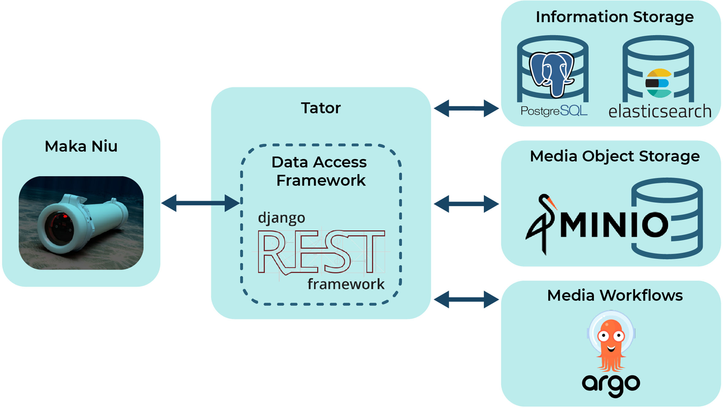
Figure 8 The Tator data ingestion pipeline and media management workflow.
3.4. User support
All test users for the initial deployment of thirteen Maka Niu units were given the opportunity to attend remote training sessions via teleconferencing with the Maka Niu engineering and software development teams. Links to an online user manual and training videos were shared during the training sessions as well as via direct email. Several additional training sessions, singly and in groups, have been offered subsequently for those who could not attend the initial sessions.
3.5. Deployments
Thirteen Maka Niu units were distributed to test users in eleven locations in 2021: Sri Lanka, Trinidad and Tobago, Cook Islands, Portugal (2), Bermuda, Seychelles, South Africa, Montserrat, and the United States (Louisiana and Hawai’i). These units are currently being tested by a subset of the twenty interviewees who provided initial input on requirements and desired capabilities for the design of Maka Niu.
Four of the units are with the development team. In September 2021, unit MakaNiu0001 was deployed on a number of dives from E/V Nautilus during an expedition in the Santa Monica Basin, off Southern California, USA. Maka Niu was strapped to the AUV Mesobot as a backup camera and recorded temperature, depth, and videos during dives (Figure 9). In total, MakaNiu0001 went on six separate dives with Mesobot to depths between 125 and 500 m. Mesobot’s missions were for the most part carried out in total darkness, but during a brief lit period, Maka Niu did capture video of flashing marine life at 100 m. The Mesobot dives provided an opportunity to compare GPS and depth data collected by MakaNiu0001 with independent coordinate information from the ship and independent pressure data collected by Mesobot, confirming the in-the-field functionality and effectiveness of the low-cost sensors built into Maka Niu. Unit 0001’s self-determined coordinates during one of the launches were only 6 m off from coordinates provided by the navigator of the ship, and at a depth of 500 m during one of the Mesobot’s deeper dives, their respective depth estimations differed by only 2 m, or 0.4%.
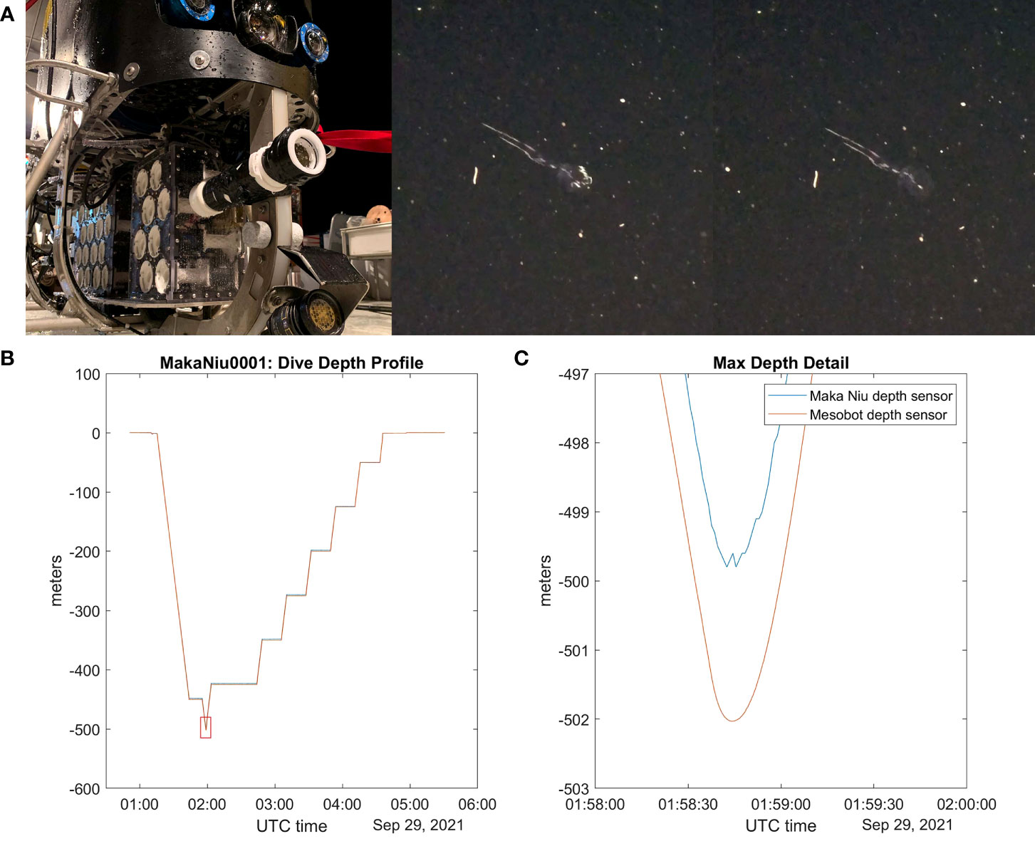
Figure 9 (A) Maka Niu was mounted to Mesobot below and in parallel to its main camera system. (B) Stills from a video recorded by Maka Niu of a flashing marine animal. (C) The depth profile for one of the dives, using independent data from Maka Niu and from Mesobot, shows the relative agreement between their measurements.
The Maka Niu system has been popular with test users for increasing the range of their Baited Remote Underwater Video (BRUV) systems. Test user Sheena Talma deployed unit MakaNiu0008 in the Maldives in September 2022 as part of a BRUV deployment to the seafloor. Maka Niu recorded extensive footage of shrimp, eels, and a bluntnose sixgill shark (Figure 10). The depth of the seafloor was approximately 900 m, and Maka Niu estimated its depth at 894.5 m and local temperature at 5.65 C.
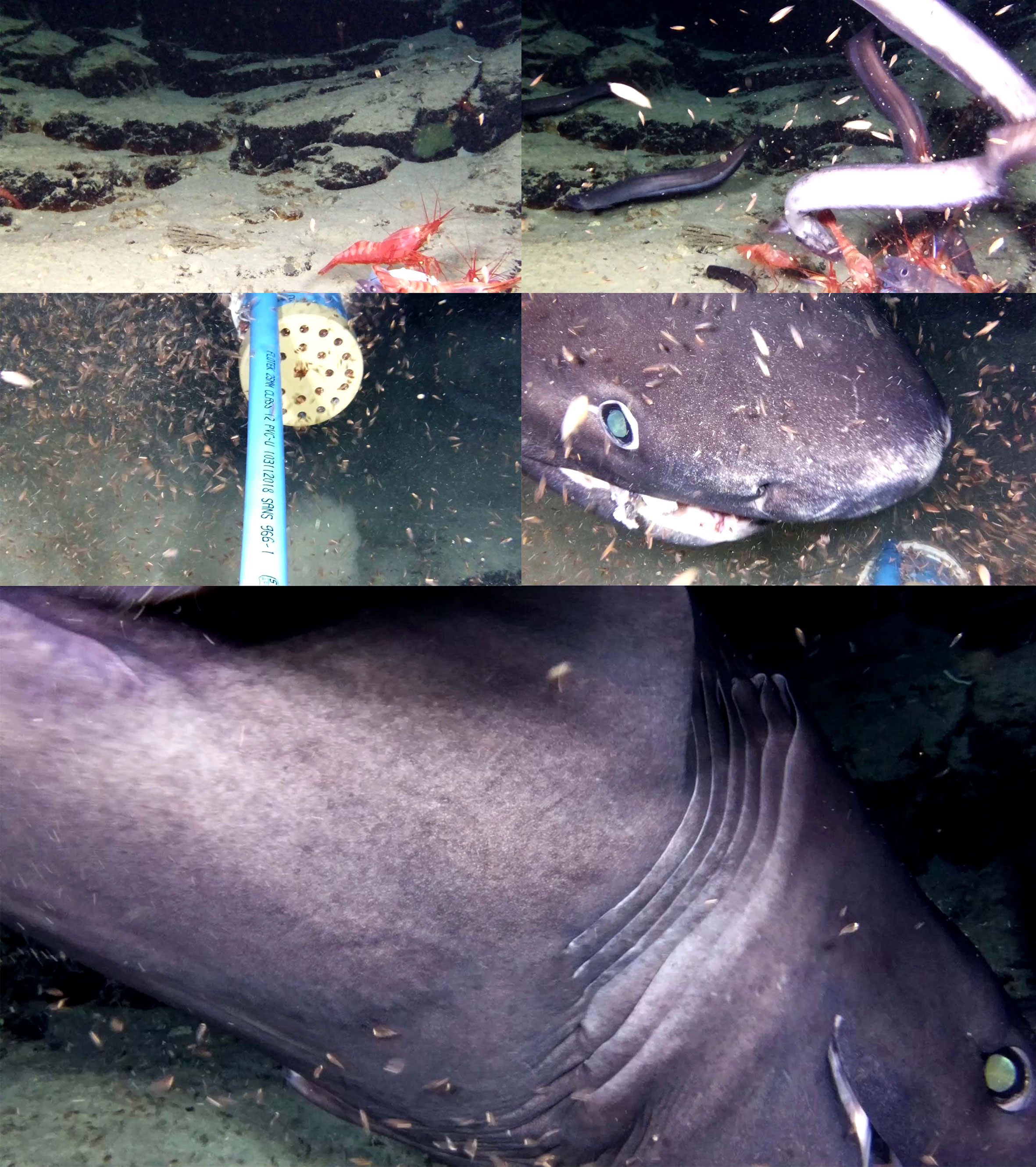
Figure 10 Video stills from a BRUV deployment to 900 m.
3.6. Testing
Housing: The 1,500 m housing rating was confirmed with two tests at a pressure testing tank at Woods Hole Oceanographic Institute (Table 1). In a destructive test, the pressure in the test tank was increased until the Maka Niu housing collapsed at 3,127 psi, equivalent to roughly 2,148 m in saltwater. In a second test, a Maka Niu was pressurized to 2,235 psi, equivalent to 1,535 m, and held there for one hour. Maka Niu was on for the duration of the second test, and remained fully functional throughout and after the test.
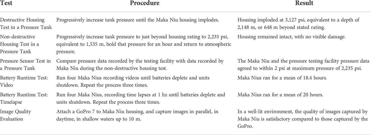
Table 1
Keller Pressure Sensor: The raw pressure data recorded by the Maka Niu during the pressure test of the housing can be compared to the pressure profile inside the testing tank (Figure 11). This comparison shows that the Maka Niu’s pressure sensor remained functional throughout the test, and that at maximum pressure, which was held for an hour at approximately 2,235 psi, the Keller recorded about 2 psi less, which is equivalent to an error of 0.09%. The uncertainty in pressure data from the testing facility is stated to be ±0.01%, and the uncertainty of the Keller sensor data from the manufacturer is 0.5% of full-scale measurement, which for the keller is 1 bar or 14.5 psi. As expected, at 1,500 m, the percent difference between the Keller sensor data and the tank pressure data falls well within the sum of the two uncertainties.
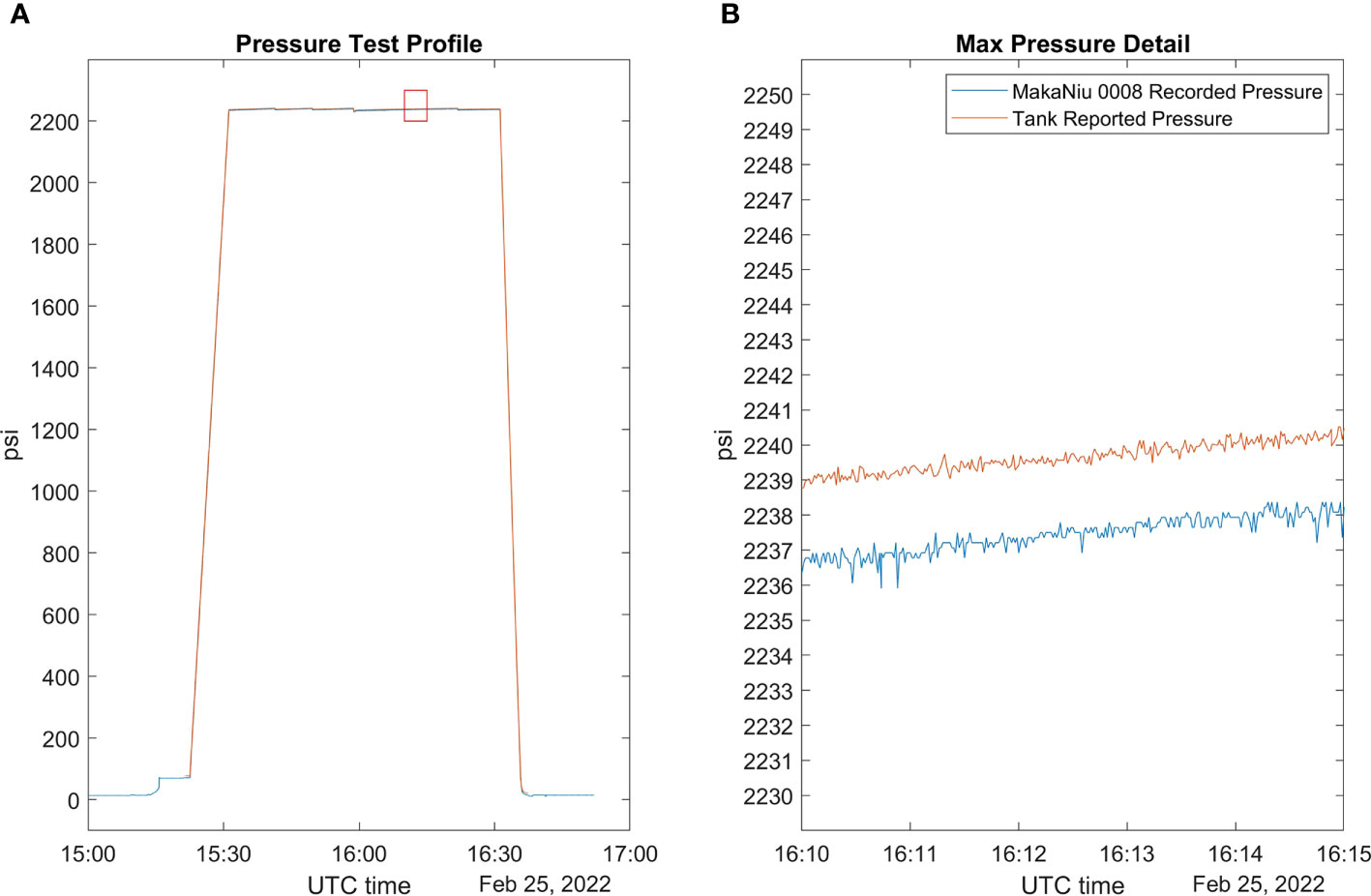
Figure 11 (A) Profile of the entire duration of the test, which pressurized the Maka Niu to approximately 2,235 psi. (B) A closeup of the pressures reported at the maximum pressure range, showing a difference of approximately 2 psi between the reported and recorded pressures.
Battery Runtime: To determine worst-case battery performance, four Maka Niu units—0004. 0005, 0007, and 0008—each performed three runtimes of continuous video recording and three runtimes of one-second timelapse image captures. The units were chilled to approximate underwater temperatures. The testing has shown that during continuous video, the units averaged 18.4 hours, and during timelapse, they averaged 20 hours. (Figure 12).
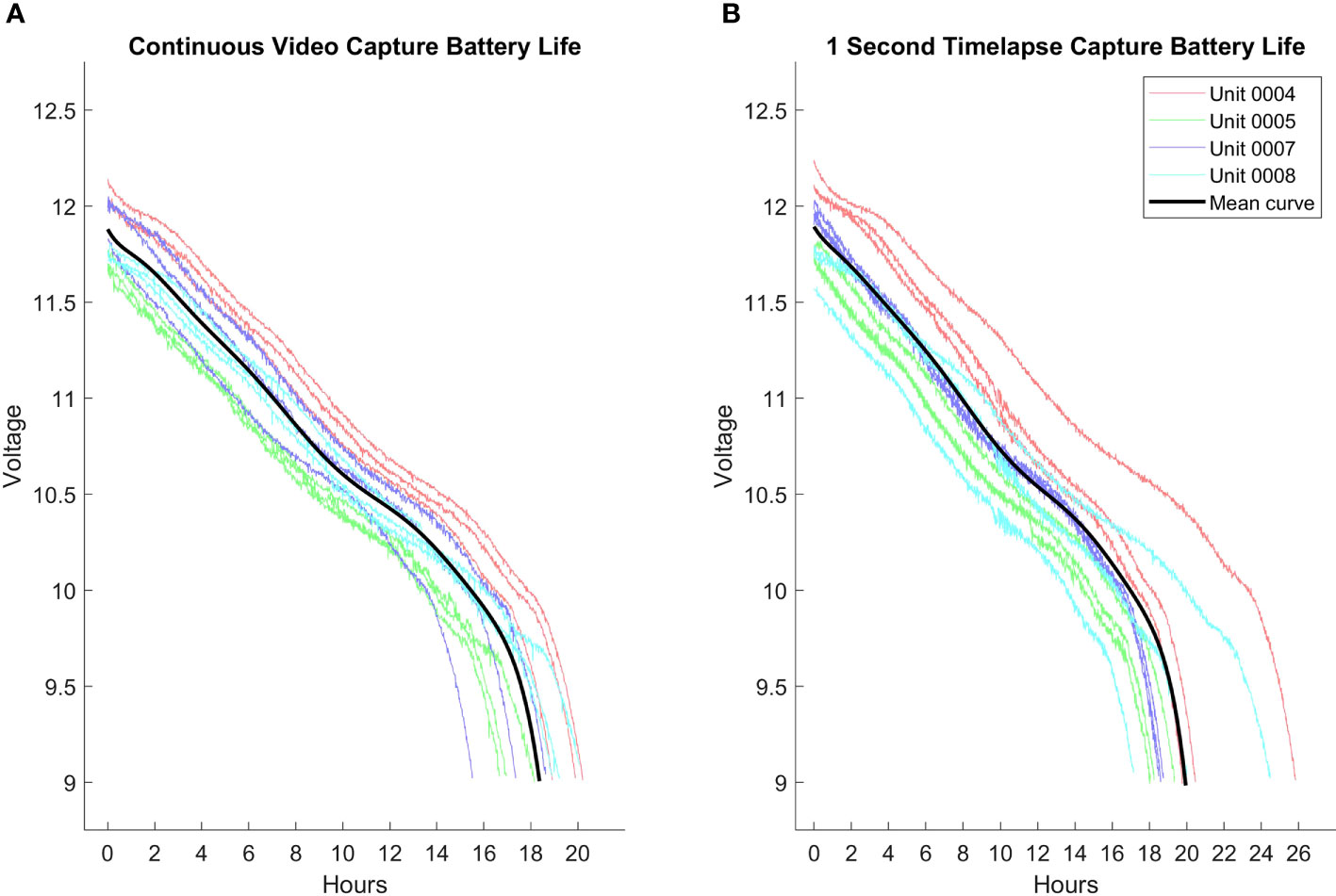
Figure 12 (A) Profile of the Maka Niu battery voltage for continuous video recording. Standard deviation for runtime duration is 1.5 hours. (B) Profile of the Maka Niu battery voltage for time-lapse imaging at 1-second intervals. Standard deviation for runtime duration is 2.6 hours. Note that the current design of the charging hardware terminates charging when current drops below a certain threshold. Since the cutoff is not based on voltage obtained, the units have inconsistent starting charge, which leads to considerable standard of deviation in the runtime duration. The mean curve in each graph was generated as a 10-degree polynomial estimation of the battery runs stretched or compressed to the average runtime of each set.
The nominally 11.1 V battery pack has up to 3,500 mAh charge. This translates to approximately 190 mA or 2.1 W when recording video, and an average 175 mA or 1.94 W with the one-second timelapse. This indicates that the power consumption difference between the camera actively recording and idling between image captures is fairly minimal. In separate measurements, it was observed that when the camera is disabled, current consumption drops almost 50 mA. If timelapses have significantly longer gaps, the camera can be powered down and battery life in timelapse mode can be expected to be increased up to 40% in the extreme limit. Further methods to increase deployment time are discussed in section 4.3.
Image Quality Evaluation: In order to perform a qualitative evaluation of the image quality captured by Maka Niu, a GoPro7 was mounted directly on a Maka Niu. The two devices were then used to take a series of images at shallow depth off the coast of Maui in Hawai’i. The images have not been post-processed. The GoPro camera has a larger sensor resolution and wider field of view, but a comparison of the matched and cropped area of coverage from each system shows that, in a well-lit environment, images from Maka Niu are well-matched with those from the GoPro (Figure 13). While 4K imagery would be advantageous, using a GoPro as the imaging sensor in the Maka Niu would add excessive additional costs to each system, and the GoPro also lacks the open source development tools available for the Raspberry Pi camera currently in use.
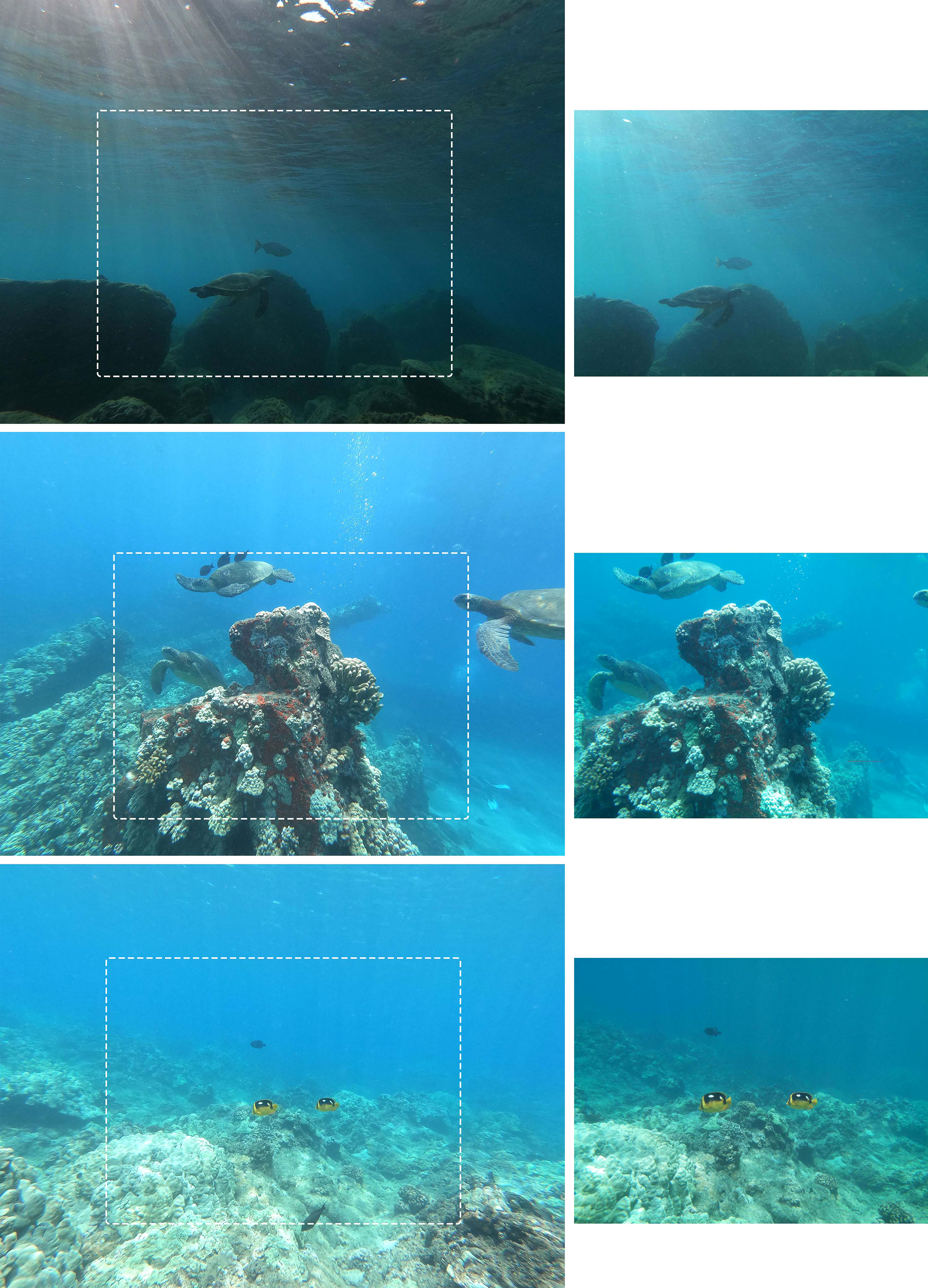
Figure 13 Images captured by GoPro7 are on the left; images captured by Maka Niu are on the right. Both devices were set to full automatic control and had post-processing disabled. The GoPro diagonal field of view is 100° and the images are 4000x3000 pixels. The Pi Camera Module V2 diagonal field of view is 62° and the images are 2592x1944 pixels. A white dotted rectangle in the figure marks the approximate cropping of the GoPro images that would result in the equivalent Maka Niu images. Since both the field view and the pixel count of the Maka Niu images are about a third of those of the GoPro, the cropped images would have roughly equivalent pixel count.
4. Discussion
The Maka Niu imaging and sensor platform is a 261 mm-long, 66 mm-diameter cylinder, currently depth tolerant to 1,500 m and designed to be the main “control” node of a network of configurable modules controlled over wave-guided wireless communications provided by the Raspberry Pi Zero W or Zero 2 W. The camera is capable of HD video resolution at 30 fps, 8 megapixel still images, and time-lapse sequences. The camera and control computer are integrated into a single unit and can be mounted in any number of configurations according to deployment needs, making it a flexible and agile addition to other ocean observation vehicles or equipment that may lack the capabilities Maka Niu provides.
Maka Niu is conceived, designed, and engineered first and foremost to be as low-cost and user-friendly in operation as possible, while still meeting the stringent and rigorous needs of deep-ocean exploration. Maka Niu is operated wirelessly throughout the life of the platform. There are no penetrators in the pressure housing that might wear and fail over time, and all electrical hardware, mechanical hardware, and software interfaces were designed to ensure this fully sealed, wireless use. Charging power is provided using wireless inductive technology; all data communication with the control computer, support modules such as the LED module, and the sensor data/media management system is handled via Wi-Fi; and the control computer is operated magnetically from outside the sealed housing.
4.1. Modularity
The current Maka Niu system is the first element of what is intended to be an extendible ecosystem of exploration, monitoring, or sampling devices that can be rapidly built around any combination of the central compute stack, power stack, and housing. While remaining deployment agnostic, multiple Maka Niu devices can be deployed together to achieve the capabilities of a much larger deep-sea platform. Creating a system of reusable modular parts allows new development to focus more readily on the novel capability being explored, without having to reinvent the computation stack, power systems, and pressure housings. To this end, three additional modules were designed and prototyped by students at the Massachusetts Institute of Technology and the University of Porto using the Maka Niu housing, power, and compute components: an LED module, an independent above-water location module, and an underwater release module.
Inter-module communication: While submerged, communication between modules can be accomplished via 2.4 Ghz Wi-Fi or Bluetooth, using the native capabilities of the Pi Zero W as long as the modules are within 10 to 15 cm of each other. If longer distances are needed, additional material can be added to the mounting chassis to operate as a waveguide for the RF signals to follow and allow inter-module communication (Jang, 2020). If even longer distances are needed, a Maka Niu acoustic modem module or another well-understood method of underwater communication can be engineered, again developing only the desired novel capability and speeding design through the reuse of pre-existing support modules.
LED module: The module is designed to use the same initial voltage as that provided by the battery subsystem and is controlled by the same compute subsystem. The primary difference between the original Maka Niu system and the LED module is that the camera module has been replaced with a constant-current LED driver circuit board, LEDs, and a heatsink. Using the same battery stack and computer stack allows for easy communication between the original system and the LED module, which increases battery conservation by programming the LEDs to activate only when the camera will be on and recording. Based on interviews with potential users, approximately 8,000 lumens per module should be sufficient for most use cases. Even with LEDs’ high efficiency, the power needed to produce sufficient light will draw enough power to create significant heat. To combat this, the LED driver circuit board should be made with an aluminum core, and a heatsink should be incorporated into the housing to conduct heat into the surrounding water. A compatible LED module will expand the types of locations and missions for which the main Maka Niu is appropriate. The combination of camera module and LED module can be mounted or configured according to current mission requirements, lending agility to mission deployments.
Completed prototypes of the LED module are now being tested, along with the feasibility of an RF waveguide armature that would enable an LED module and a Maka Niu camera to coordinate actions underwater (Figure 14). In initial testing, we have demonstrated both Wi-Fi and Bluetooth communication between a camera and a light pair that were held 12 inches apart by a Delrin armature. For the test to succeed, the armature needed to be wrapped in aluminum foil to reflect RF signals back into the Delrin medium. We will be confirming this capability in the field in saltwater environments and designing new armatures that have integrated RF reflective surfaces.
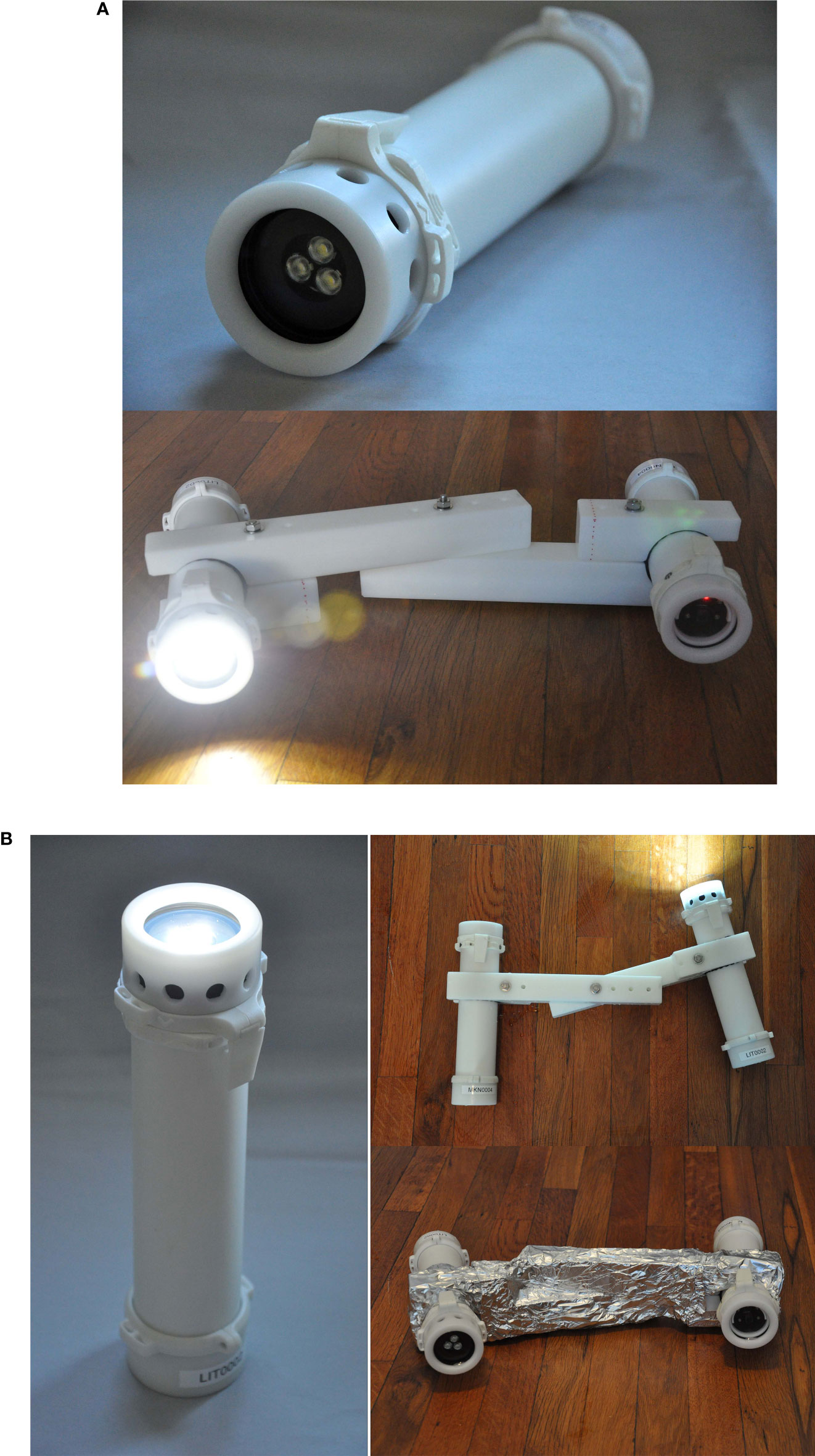
Figure 14 (A) The LED module uses the same housing as the Maka Niu, except the front hold-down is replaced with a copy of the rear hold-down, and water access holes are added for heat-sinking purposes. (B) This Delrin armature holds an LED module at an adjustable distance and angle to provide ideal lighting conditions. The armature was also used to test RF-guided Wi-Fi and Bluetooth communication. This did not successfully maintain the connection once submerged until it was wrapped with aluminum foil to act as a waveguide.
For use as a dive light, the LED module is controlled using the same 6-position control dial and push button interface.
Independent above-water location module: The location module is based on a commercially available personal locator encapsulated in a standard Make Niu housing and equipped with a saltwater switch that triggers it to begin broadcasting the GPS position of the module when it reaches the surface. While submerged, the system remains inactive. When the platform reaches the surface, the location system activates and the GPS coordinates are transmitted via SPOT Trace, a satellite communication technology that can transmit its location globally as part of the Globalstar satellite network. The GPS location can be sent as an SMS text message or email, or visualized via SPOT Trace’s web-based app. The location module uses the standard Maka Niu pressure housing and power subsystem, but exchanges the camera subsystem with an ESP32 and SPOT Trace device.
Underwater release module: The underwater release module allows Maka Niu to be deployed as a benthic lander and is based on a self-contained magnetic mechanism triggered by a control signal sent by the main Maka Niu control module. First, flotation material is added to achieve positive buoyancy ensuring the unit returns to the surface. Next, the release system consists of a weight of ferromagnetic material attached directly to the release module’s housing, attracted by the magnet, and acting as an anchor to provide negative buoyancy. Upon mission completion, the release mechanism activates, releasing the weight and consequently causing the Maka Niu to ascend to the surface. The pressure housing and power supply system are duplicates of the base system. The logic of the release system is integrated into the mission engine running aboard the Raspberry Pi in the main control module. The communication between this external module and the Raspberry Pi is achieved via Bluetooth. An ESP32 or similar Wi-Fi and Bluetooth-enabled microcontroller platform receives a control signal sent by the Raspberry Pi and releases the weight based on the signal received. The coupling mechanism used in this iteration is based on a permanent magnet housed within the enclosure, which attracts ferromagnetic material to operate as an anchor. When a control signal is received by the ESP32 in the external module, an electromagnetic pulse is sent to a coil surrounding the magnet, temporarily nullifying or “bucking” the force of the magnet, which results in the anchor weight being ejected. As a safety backup, the coupling mechanism is attached to the anchor mass via a galvanic time release (GTR) coupler that undergoes timed corrosion in saltwater. Should an error occur in the control system, or insufficient power be provided to the magnet, the GTR mechanism will degrade after a predetermined amount of time, allowing the device to return to the surface.
4.2. Increasing pressure rating
The current Delrin housing and acrylic port can be swapped, with minimal design changes, to an aluminum housing with a sapphire glass port. We estimate that this change would increase the depth rating to 6,000 m, leading to a version of Maka Niu capable of deployment to the vast majority of the sea floor. The currently used pressure sensor would be swapped for the Series 7LHP, also by Keller.
There are some expected challenges, however. Maka Niu depends a great deal on wireless technologies: global positioning, Wi-Fi, and inductive charging. As a metal housing will likely interfere with these elements, compromises, workarounds, and alternate solutions will need to be explored.
4.3. Improving deployment length
There is a great deal of room for improvement in the power performance of the Maka Niu. The current BMS does not have adequate control over power to individual sensors and chips. For instance, there is no reason to power the GNSS chip when the Maka Niu is under water. It consumes nontrivial current as it searches for satellites, but because it is tied to the same power rail as the Keller pressure sensor, it cannot be fully powered down. Additionally there is no ability to schedule a wakeup of the Pi Zero W if it is put to sleep or powered down. Adding the capability to schedule shutdowns and reboots will drastically increase the variety and potential length of deployments. For instance, a user may be interested in only recording at sunrise and sunset. If at all other times, the BMS can fully power down the Pi Zero W and all sensors other than a clock, Maka Niu could conceivably be deployed for weeks at a time.
4.4. Conclusion
The system we present is realizable by the educational, citizen science, and research communities. Maka Niu is intended as an extensible, open-source framework similar to the Phillips et al. (2019) 5,500 m DEEPi camera system. Maka Niu’s small size means it is deployable from almost any size vessel and can be combined with larger research platforms to extend their capabilities, as well.
The use of commercial off-the-shelf components such as the Raspberry Pi Zero W and Zero 2 W decreases cost and increases the number of potential users, thus adding to the overall capacity of ocean observation and monitoring. The Raspberry Pi Zero W systems afford wireless communication with any Wi-Fi capable device, including smartphones and tablets, and allow software development using open-source operating systems and programming frameworks such as Linux, Python, and Node.js to create user interface designs operable by non-experts. Rather than building an all-in-one, multimillion-dollar seagoing platform that attempts to be all things to all researchers, the distributed, modular nature of an extendible ecosystem of capabilities offers flexibility and proportional response to the needs of any deployment.
Often, “affordable” in oceanography describes instruments that cost upwards of tens of thousands of dollars (versus millions). To be sure, this is a significant decrease, but at the same time, tens of thousands of dollars is still unaffordable for many individuals and organizations, particularly in developing areas. The estimated bill of materials for the current design for a single unit of Maka Niu is less than $1,000 USD, excluding labor costs, for the production of fewer than 20 units. Maka Niu is, however, aimed at wide distribution and is designed to take advantage of mass production and economies of scale. We estimate that the bill of materials for an at-scale run of 10,000 Maka Niu systems would be less than $300 USD for each device, again excluding labor costs. The current GoPro Hero 10 Black, equipped with the most robust commercially available housing, can dive to a maximum of 60 m and collect imagery up to a resolution of 5.3K for a total cost of ~$550 USD. It lacks Maka Niu’s suite of sensors necessary for deep-ocean scientific research and exploration, many of the basic mission programming options, as well as the ability to develop an extended ecosystem of modules to provide expanded capabilities.
Maka Niu’s value as a low-cost data acquisition system is further extended by its integration with Tator, the open-source, online platform that enables seamless image and data upload, management, and analysis. Tator and FathomNet will later be integrated to enable automated localization and classification of imagery collected during deployment (Katija et al., 2022).
Maka Niu’s low cost, ease of use, and ever-expanding ecosystem of open source modules provides deep-ocean observation and sampling capabilities for a cross-spectrum of stakeholders—from traditionally funded ocean institutes and trusts, to underfunded research programs in remote island nations, to unfunded citizen science networks, student clubs, and classrooms. These newly accessible deep-ocean capabilities are then amplified and supported by Maka Niu’s integration with state-of-the-art machine learning technologies to speed the classification of samples and allow faster and wider dissemination of novel discoveries.
Data availability statement
The original contributions presented in the study are included in the article/Supplementary Material. Further inquiries can be directed to the corresponding author.
Author contributions
DN, JC, KB, and AA contributed to the conceptualization of the device. DN managed the project and contributed to software and hardware selection, programming, prototyping, and testing, LK contributed to designing, fabrication, mechanical engineering, programming, and testing. JF programmed the mission engine, mission programming app, wireless configuration tool, and data upload tool, and contributed to the UI/UX design. MS contributed to the design of the LED module. PB contributed to the evaluation of open source web servers, the data upload methodology, and mission programming methodology. JS contributed to the development of a weight-release deployment module. KC contributed to the UI/UX design, the user manual, and quick start guide. BW contributed to integration with Tator and FathomNet. KLCB and AA supervised all teams as Principal Investigators. All authors contributed to the article and approved the submitted version.
Funding
This work was funded by the MIT Portugal Program, MIT Media Lab Open Ocean Initiative, MIT Future Ocean Lab, Oceanic Labs, and the Ocean Discovery League.
Acknowledgments
A very special thanks to Nainoa Thompson, Lehua Kamalu, Sonja Swenson Rogers, Chris Blake, and Noelani Kamalu of the Polynesian Voyaging Society. We thank Alexis Hope and Maud Quinzin from the Open Ocean Participatory Design Team. We are grateful to the interviewees who participated in the participatory design study on technical and human capacity needs for deep-sea exploration: Diva Amon, Chris Blake, JS, Salome Buglass, Jessica Cramp, Asha de Vos, Zoleka Filander, Peter Girguis, Lehua Kamalu, Brian R.C. Kennedy, Ashley Knight, Nuno Lourenço, Miriam Lynch, Craig McClain, Kaitlin Noyes, Tim Noyes, Randi Rotjan, Sheena Talma, Veta Wade, and an interviewee. We could not have made progress without the test users of Maka Niu: Osei Agyapong, Diva Amon, João Andrade, Chris Blake, Corie Boolukos, JS, João Costa, Jessica Cramp, Asha de Vos, Zoleka Filander, Lehua Kamalu, Noelani Kamalu, Nuno Lourenco, Craig McClain, Kaitlin Noyes, Tim Noyes, Andreas Ratteray, Caroline Schio, Sheena Talma, Veta Wade. We would like to thank the teams involved with the Maldives-Nekton 2022 expedition that enabled the deployment of the Maka Niu during the expedition. A special thank you to the Maldives Marine Research Institute and Nekton Foundation for supporting deployments. A special thank you to the National Research Foundation - South African Institute for Aquatic Biodiversity team for enabling the deployment attached to their Lander systems. Special thanks to the University of Porto “Delta Team” students for prototyping the weight-release and above-water location modules: Diogo Silva, Hugo Pires, Francisco Machado, João Campos, Margarida Santiago, Mário Cardoso, Miguel Pinto, Samuel Pereira, Tiago Martins, and Tomás Moreno. We very much appreciate the contribution of Dr. Andrew ‘Zoz’ Brooks to the endcap design. We’d like to formally acknowledge the efforts of Fred Marin in this project. We thank Fredrick D. Marin and Dr. Dana Yoerger for letting Maka Niu deploy with the DAVPR profiler and with the Mesobot AUV on the Nautilus team cruise NA131. Huge thanks to our former admin, Amna Carreiro, for all her patience.
Conflict of interest
Author BW was employed by the company CVision AI.
The remaining authors declare that the research was conducted in the absence of any commercial or financial relationships that could be construed as a potential conflict of interest.
The reviewer JJ declared a shared affiliation with the author MS to the handling editor at the time of review.
Publisher’s note
All claims expressed in this article are solely those of the authors and do not necessarily represent those of their affiliated organizations, or those of the publisher, the editors and the reviewers. Any product that may be evaluated in this article, or claim that may be made by its manufacturer, is not guaranteed or endorsed by the publisher.
Supplementary material
The Supplementary Material for this article can be found online at: https://www.frontiersin.org/articles/10.3389/fmars.2022.986237/full#supplementary-material
Footnotes
References
Almero V. J. D., Palconit M. G. B., Alejandrino J. D., Concepcion R. S., Vicerra R. R. P., Sybingco E, et al. (2021). “Development of a raspberry pi-based underwater camera system for inland freshwater aquaculture”. (2021 IEEE 13th International Conference on Humanoid, Nanotechnology, Information Technology, Communication and Control, Environment, and Management (HNICEM) pp. 1–6. doi: 10.1109/HNICEM54116.2021.9731987
Amon D. J., Rotjan R. D., Kennedy B. R.C., Alleng G., Anta R., Aram E., et al. (2022). My deep Sea, my backyard: a pilot study to build capacity for global deep-ocean exploration and researchPhil. Trans. R. Soc 377, B3772021012120210121. doi: 10.1098/rstb.2021.0121
Bell K. L. C., Chow J. S., Hope A., Quinzin M., Cantner K. A., Amon D. J., et al. (2022). Low-cost, deep-Sea imaging and analysis tools for deep-Sea exploration: A collaborative design study. Front. Mar. Sci 9. doi: 10.3389/fmars.2022.873700
Bergshoeff J. A., Zargarpour N., Legge G., Favaro B. (2016). How to build a low-cost underwater camera housing for aquatic research. FACETS 2, 150–159. doi: 10.1139/facets-2016-0048
Boulais O., Woodward B., Schlining B., Lundsten L., Barnard K., Bell K. C., et al. (2020). FathomNet: An underwater image training database for ocean exploration and discovery arXiv. doi: 10.48550/arXiv.2007.00114
Cazenave F., Kecy C., Risi M., Haddock S. H. D. (2014). SeeStar: A low-cost, modular and open-source camera system for subsea observations. in 2014 oceans Low-Cost, Deep-Sea Imaging and Analysis Tools for Deep-Sea Exploration: A Collaborative Design Study Vol. 1–7 (St. John’s) 2014. doi: 10.1109/OCEANS.2014.7003077
Eakins B. W., Sharman G. F. (2012). Hypsographic curve of earth’s surface from ETOPO1 (Boulder, CO: NOAA National Geophysical Data Center).
Giddens J., Turchik A., Goodell W., Rodriguez M., Delaney D. (2021). The national geographic society deep-Sea camera system: A low-cost remote video survey instrument to advance biodiversity observation in the deep ocean. Front. Mar. Sci 7. doi: 10.3389/fmars.2020.601411
Hardy K., Cameron J., Herbst L., Bulman T., Pausch S. (2013). “Hadal landers: The DEEPSEA CHALLENGE ocean trench free vehicles,” in 2013 OCEANS, Low-Cost, Deep-Sea Imaging and Analysis Tools for Deep-Sea Exploration: A Collaborative Design Study vol. 1–10. (San Diego) 2013. doi: 10.23919/OCEANS.2013.6741368
Jang J. (2020). Marine snow tracking stereo imaging system (S.M., Massachusetts Institute of Technology, School of Architecture and Planning, Program in Media Arts and Sciences). Available at: https://hdl.handle.net/1721.1/129279.
Jolles J. W. (2021). Broad-scale applications of the raspberry pi: A review and guide for biologists. Methods Ecol. Evol. 12, 1562–1579. doi: 10.1111/2041-210X.13652
Katija K., Orenstein E., Schlining B., Lundsten L., Barnard K., Sainz G., et al. (2022). FathomNet: A global underwater image training set for enabling artificial intelligence in the ocean. Sci Rep 12: 15914. doi: 10.1038/s41598-022-19939-2
Marini S., Bonofiglio F., Corgnati L. P., Bordone A., Schiaparelli S., Peirano A. (2022). Long-term automated visual monitoring of antarctic benthic fauna. Methods Ecol. Evol 13 (8), 1746–1764. doi: 10.1111/2041-210X.13898
Marini S., Corgnati L., Mantovani C., Bastianini M., Ottaviani E., Fanelli E., et al. (2018). Automated estimate of fish abundance through the autonomous imaging device GUARD1. Measurement 126, 72–75. doi: 10.1016/j.measurement.2018.05.035
Marini S., Griffa A., Aliani S., Conversi A., Shroeder K., Borghini M. (2013) EP2863257 underwater images acquisition and processing system. Available at: https://data.epo.org/gpi/EP2863257B1.
Phillips B. T., Licht S., Haiat K. S., Bonney J., Allder J., Chaloux N., et al. (2019). DEEPi: A miniaturized, robust, and economical camera and computer system for deep-sea exploration. Deep Sea Res. Part I: Oceanogr. Res. Papers 153, 103136. doi: 10.1016/j.dsr.2019.103136
Keywords: deep sea, exploration, technology, user-centered design, machine learning, participatory design, co-design
Citation: Novy D, Kawasumi L, Ferguson J, Sullivan M, Bell P, Chow JS, de Sousa JB, Cantner KA, Woodward B, Adams A and Bell KLC (2022) Maka Niu: A low-cost, modular imaging and sensor platform to increase observation capabilities of the deep ocean. Front. Mar. Sci. 9:986237. doi: 10.3389/fmars.2022.986237
Received: 04 July 2022; Accepted: 18 October 2022;
Published: 17 November 2022.
Edited by:
Paolo Favali, ERIC foundation (Italy), ItalyReviewed by:
Jules S. Jaffe, University of California, San Diego, United StatesAndreas Marouchos, Commonwealth Scientific and Industrial Research Organisation (CSIRO), Australia
Hong Song, Zhejiang University, China
Copyright © 2022 Novy, Kawasumi, Ferguson, Sullivan, Bell, Chow, de Sousa, Cantner, Woodward, Adams and Bell. This is an open-access article distributed under the terms of the Creative Commons Attribution License (CC BY). The use, distribution or reproduction in other forums is permitted, provided the original author(s) and the copyright owner(s) are credited and that the original publication in this journal is cited, in accordance with accepted academic practice. No use, distribution or reproduction is permitted which does not comply with these terms.
*Correspondence: Dan Novy, bm92eXNhbkBtaXQuZWR1
†These authors have contributed equally to this work and share first authorship
‡These authors have contributed equally to this work and share senior authorship