 Iqbal Athal1†
 Ioannis E. Sarris
 Palani Velusamy
- 1Department of Mathematics, PSNA College of Engineering and Technology, Dindigul, Tamilnadu, India
- 2Department of Mechanical Engineering, University of West Attica, Athens, Greece
- 3Department of Mathematics, Sri Vijay Vidyalaya College of Arts and Science, Krishnagiri, Tamilnadu, India
- 4Department of Mathematics, Dmi St John The Baptist University, Lilongwe, Malawi
The method of regular perturbation is used to analyse the fully developed flow and heat transfer in a vertical two-way channel containing a permeable liquid. The Brinkman model is used for flow through porous media. The energy equation contains a viscosity term and a Darcy dissipation term. The fully conductive thin partition is divided into two stages; the wall is uniformly heated; and the effects of the porous parameter σ and the mixed convection parameter λ on the velocity and temperature distribution near the hot and cold walls are investigated. The results show that these effects mainly depend on the position of the baffle. Analytical solutions are first used to resolve the simpler problems of either a negligible Brinkman number or a negligible Grashof number. Then, using a perturbation series method, the combined effects of buoyant forces and viscous dissipation are examined. The velocity field and the temperature field in the cases under study were assessed.
1 Introduction
The study of heat transmission between liquid layers and/or between flowing liquids and nearby interfaces when a liquid moves is known as convective heat transfer (when they are not at different temperatures). Heat transfer is typically separated into two basic processes: forced convection, which occurs when the liquid moves as a result of wind, fans, or the movement of the heated object itself. On the other hand, there is no such external induction offered. Power of flow happens in a natural way. Therefore, this phenomenon is known as natural convection. One of the fundamental issues in heat transfer is the free convective heat transfer between finite vertical parallel plates suspended in a still viscous liquid.
An essential method of heat transfer in building insulation is natural convection. This phenomena is mostly investigated from the standpoint of fundamental heat transfer research within the framework of a straightforward rectangular free-convection model. packed with a thick liquid and wrapped. Aung researched the asymmetries in wall heating (Aung and Worku, 2018). Free convection in the bowl is a fairly broad topic with numerous applications in real-world engineering scenarios. The fully developed heat transfer natural convection in a vertical channel with a symmetrical constant wall temperature was explored by Bodiya and Osterle (Bodia and Osterle, 1962).
For the coupled natural convection of heat and mass movement in a vertical channel with asymmetric boundary conditions, Wood and Nelson developed an analytical solution (Nelson and Wood, 1989). Darcy’s law has been found to be insufficient for formulating liquid flow and heat transfer problems in porous media with fixed boundaries. Heat transfer in porous media is based on the Darcy flow model. Based on aperture, the Reynolds number is higher than 1. As a result, the limit as well as inertia must be taken into account simultaneously. Convective heat transmission in a vertical channel and an asymmetrical constant wall temperature were combined in a natural hypothesis put out by (Chung and Hsu, 1984; Dutta and Dutta, 1998).
The recent study by Tien and Vafai (Vafai and Tein, 1981) provides an overview of the body of research on natural convection in porous media and highlights the significance of non-Darcy factors like inertia and boundary effects since they can be used to supplement Darcy’s law in constrained applications. Chemical equations like pressure gradient and bulk viscous resistance in a highly porous material are connected to Darcy’s law. Darcy’s law’s mathematical justification can overlook the effects of solid boundaries or inertia forces on fluid flow and heat transmission through porous media.
When the fluid speed is high, inertia and boundary effects generally become important, which causes heat transfer to occur near the wall. Theoretically, inertia and boundary effects are modelled by adding a viscous component and a velocity term to the momentum equations. (Cheng, 2006) in Cheng Numerical research was done on the non-Darcy effects on the transient natural convection physical phenomena flow close to an equal vertical flat surface contained in an extremely porous medium. Foam metals and fibrous media are two examples of porous materials with high porosities. According to Cheng’s findings, the non-Darcy area is significantly more significant in high body media. The rate of fluid streaming within the thermal physical phenomena and the rate of heat transfer are both observed to be decreased by the inertia and barrier effects.
For instance, stratified environments exist in lakes for cooling ponds, solar ponds, and the atmosphere. The improvement of heat transfer in the vertical channel, if the surface is a part of the enclosure, might be a major goal due to its practical importance in many engineering systems, such as the collection of alternative energy and the cooling of electronic systems. Utilizing rough surfaces, turbulent promoters, swirl flow devices, etc. increases convective heat transfer in a vertical channel.
Research interest in the unconventional physics that controls the operation and production of micro- and nano-scale devices such as micropumps, heat exchangers for electronic devices, gas chromatography analyzers, and other micro-electro-mechanical systems is growing as a result of advancements in fabrication techniques and microfluidics (Karniadakis et al., 2005; Whitesides, 2006; Anna, 2016; Wei, 2020). Since then, numerous investigations (Maurer et al., 2003; Ewart et al., 2007) and (Cheng and Giordano, 2002; Whitby and Quirke, 2007) have confirmed this improvement for liquid flows through nanotubes and gas flows via microchannels at varying rarefaction levels.
Umavathi (Umavathi, 2011) analyses how a thin, totally conductive barrier affects the fully formed laminar mixed convection in a vertical channel holding micropolar fluid. The steady wall temperatures of the channel change. It is possible to derive analytical expressions for velocity and microrotation velocity. The effects of the material parameter, the baffle position, and the Grashof number to Reynolds number ratio on the velocity and microrotation velocity are analysed numerically and graphically, respectively. It is discovered that the material parameter is invariant on velocity but promotes the microrotation velocity, and that the ratio of the Grashof number to the Reynolds number suppresses the velocity while promoting the velocity. The double-passage channel with a can also experience flow reversal.
This study examines the impact of viscous dissipation on fully developed mixed convection in a vertical plate whose walls conduct heat to an external fluid based on the findings of (Umavathi, 2011). Both instances of the external fluid’s reference temperature being equal and different are taken into consideration. Analytical solutions are first used to resolve the simpler problems of either a negligible Brinkman number or a negligible Grashof number. Then, using a perturbation series method, the combined effects of buoyant forces and viscous dissipation are examined. The velocity field and the temperature field in the cases under study were assessed. The perturbation parameter in the future has been selected to be the pure number Gr. Both the scenario of symmetric fluid temperatures with equal Biot numbers and asymmetric fluid temperatures with varying Biot numbers have been taken into consideration. Following is a summary of the findings: The dimensionless velocity u and the dimensionless temperature u are rising functions of the viscous dissipation parameter for upward flow at each location. For downward flow, u is an increasing function at every place while u is a decreasing function. More crucial for upward flow than for downward flow is the impact of u and n on the Nusselt values. The value is decided uniquely in the case of full symmetry.
2 Mathematical formulation
By introducing a thin, conductive baffle, as seen in Figure 1, the channel is divided into two passageways. Considered here are fluids that are permeable, incompressible, laminar, and two dimensional in a channel. At the same upward vertical speed and constant temperature, the fluid enters the channel. The temperature applied to the channel walls is completely different and steady. With the exception of the buoyancy element in the momentum equation, the fluid properties are considered to remain constant. It is assumed that the temperature gradient and the transverse velocity in the axial direction are both zero for fully developed flow.The governing equations are as follows when viscous dissipation is taken into account:
where stream I or stream II is indicated by the subscript i. As for the boundary conditions,
Wood has suggested that the reference temperature in the fully developed region be set at the mean fluid temperature. The reference temperature used in the current work is the mean temperature of the walls, i.e.
The governing equations are as follows:
where
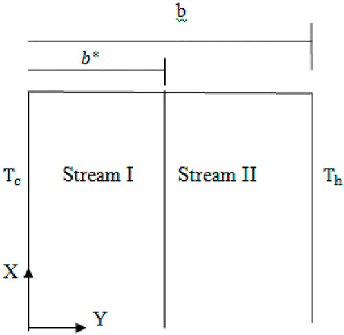
FIGURE 1. Physical configuration.
3 Solution
Equations (2.4) and (2.5), along with boundary conditions (2.6), define the fundamental equations driving the flow. These equations are highly coupled and non-linear. The regular perturbation approach, however, can be used to find approximations of solutions.
Stream: 1
Stream 2:
where ɛ = Br is chosen as the perturbation parameter.
Using equations (3.1),(3.4) in the equations (2.4),(2.6), we have
Stream 1: Zeroth order equations
Stream 2: Zeroth order equations
First order equations
Zeroth order boundary conditions:
First order boundary conditions:
Zeroth order solutions: In addition to boundary and interface conditions, the zeroth order differential equations (3.5), (3.6), (3.9), (3.10) have solutions as follows:
Stream 1:
Stream 2:
First order solutions: First order differential equations (3.7)-(3.8) with boundary and interface conditions (3.14) have the following solutions:
Stream 1:
Stream 2:
The constants appeared in the above equations are given in the Appendix section 6.
4 Results and discussion
When the baffle is placed close to a cold wall, Figure 2, Figure 3, Figure 4, Figure 5, Figure 6 show how the porosity parameter σ and the mixed convection parameter λ affect velocity and temperature. Figure 2 and Figure 3 show, respectively, the impact of the buoyancy-to-inertia force on velocity and micro rotational velocity for various baffle positions. For rising values of λ > 0, the maximum point of the velocity profile for each graph shifts to the right wall, and as a result, the velocity drops near the left wall. For higher values of λ > 0, on the other hand, the highest point of the velocity profile shifts to the left side, and as a result, the velocity drops towards the right wall. The stronger the upward velocity, the larger the value of λ > 0. The flow reversal is found close to the left wall, especially for sufficiently large values of λ > 0.
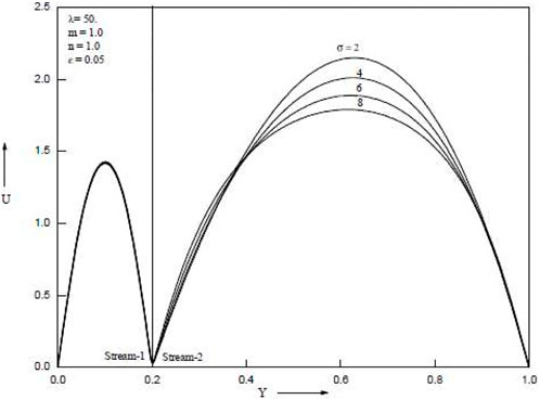
FIGURE 2. Velocity for different values of σ = 2, 4, 6, 8.
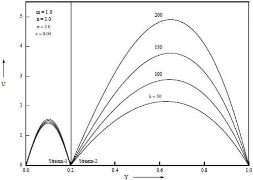
FIGURE 3. Velocity for various mixed convection values λ = 50, 100, 150, 200.

FIGURE 4. Temperature for various values of σ = 2, 4, 6, 8.
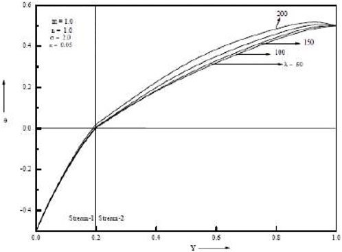
FIGURE 5. Temperature for various mixed convection values λ = 50, 100, 150, 200.
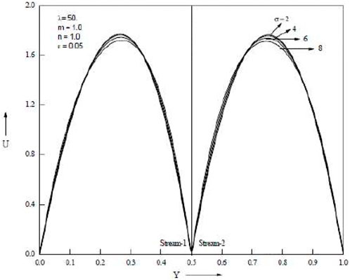
FIGURE 6. Velocity for various values of σ = 2, 4, 6, 8.
When lambda is more than zero, the maximum velocity point in the broader passage travels toward the hot side, while when lambda is less than zero, it moves toward the cool side. The highest velocity point for the narrower tunnel occurs almost in the centre of the passage whether or not λ > 0 or λ0. Similar patterns are produced in the two passages for both λ > 0 and λ < 0 when the baffle is in the middle of the channel. Figure 3 shows the impact of the buoyancy-to-inertia force λ on the velocity for various baffle positions. Stronger descending velocities result from bigger values of λ > 0. Conversely, for λ < 0, larger values of λ result in stronger upward velocities. This outcome runs counter to the velocity. For baffle positions of .2 and .8, the maximum and minimum points of the velocity are found close to the hotter wall and the colder wall, respectively. There are two maximum/minimum locations for the velocity profiles when the baffle position is in the centre of the channel.
Temperature increases are as seen in Figure 4 and Figure 5, which demonstrate an increase in the porous parameter σ and the mixed convection parameter λ. Figure 6 shows that when the baffle is positioned in the centre of the channel, the porous parameter σ rises and velocity in both streams falls. When the baffle is placed close to the cold wall as opposed to in the middle of the channel, it is noticed that the magnitude of suppression is greater. Both streams’ velocities rise as the mixed convection parameter λ rises. Temperature rises in both streams as porous parameter σ and mixed convection parameter λ increase. The Grashof number, which is the ratio of buoyant force to viscous force, actually increases when the mixed convection parameter λ increases. Figure 7 and Figure 8 show temperatures for various porosity parameter values (σ) and temperatures for various mixed convection values (λ). According to Figure 9, as the porosity parameter σ grows, the velocity in both streams drops.
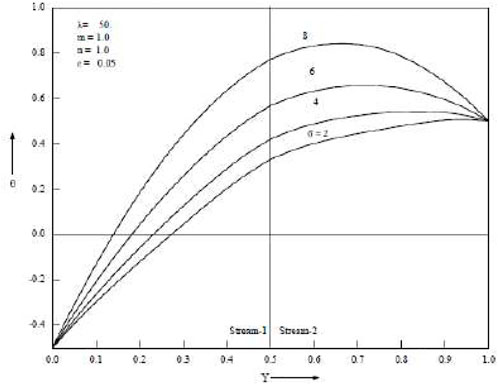
FIGURE 7. Temperature for various values of σ = 2, 4, 6, 8.
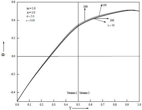
FIGURE 8. Temperature for various values of λ = 50, 100, 150, 200.
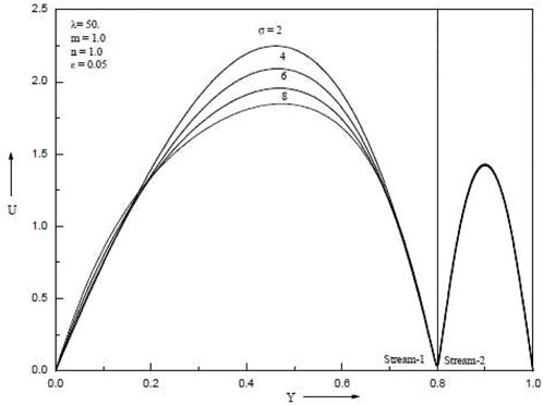
FIGURE 9. Velocity for various values of σ = 2, 4, 6, 8.
5 Conclusion
In this, a vertical double passage channel containing a permeable liquid is used to study the fully developed flow and heat transfer using a regular perturbation method. The Brinkman model is employed to depict the distribution of velocity and temperature during flow through porous material. Conclusion: The porosity parameter σ should reduce velocity while increasing temperature. When the baffle is situated at the cold, middle, and close to the hot walls of the double passage channel, the mixed convection parameter λ enhances the velocity and temperature.
A vertical double passage channel with a permeable fluid inside of it has been the subject of an analytical inquiry into the laminar mixed convection. An ideal conductive, thin-plane baffle is used to separate the channel into two passageways. The evolution of the channel’s velocity and permeability velocity profiles has been shown. The parametric analysis was conducted to assess how the material factors affected the velocity at various baffle positions. The average flow velocity U (as a parameter that can be changed in a genuine laboratory experiment) has also been provided in addition to the thermal wall requirements. Analytical series expansion has been used to solve the governing and energy balance equations.
• The velocity is barely impacted by the material parameter. The channel length affects how the material parameter affects the permeability velocity.
• As long as U does not reach a maximum value, there may be upward (U > 0) and downward (U < 0) laminar flow solutions within the range of the incoming surface heat flux.
• The existence domain is open to all negative values of U and is not constrained from below.
• Although the mechanical and thermal properties of the flows described by the dual solutions are very different, they gradually converge when the stipulated U approaches the upper limit of what is permitted.
Data availability statement
The original contributions presented in the study are included in the article/Supplementary Material, further inquiries can be directed to the corresponding author.
Author contributions
The authors declare that the study was realized in collaboration with equal responsibility. All authors read and approved the final manuscript.
Conflict of interest
The authors declare that the research was conducted in the absence of any commercial or financial relationships that could be construed as a potential conflict of interest.
Publisher’s note
All claims expressed in this article are solely those of the authors and do not necessarily represent those of their affiliated organizations, or those of the publisher, the editors and the reviewers. Any product that may be evaluated in this article, or claim that may be made by its manufacturer, is not guaranteed or endorsed by the publisher.
References
Anna, S. L. (2016). Droplets and bubbles in microfluidic devices. Annu. Rev. Fluid Mech. 48, 285–309. 48, Annual Reviews, Palo Alto, CA. doi:10.1146/annurev-fluid-122414-034425
Aung, W., and Worku, G. (2018). Theory of fully developed mixed convection flow: Exact reversal. ASME J. Heat. Transf. 108, 485–488. doi:10.1115/1.3246958
Cheng, F. (2006). Fully developed natural convection heat and mass transfer of a micropolar fluid in a vertical channel with asymmetric wall temperatures and concentrations. Int. Conf. Heat Mass Transf. 33, 627–635. doi:10.1016/j.icheatmasstransfer.2006.01.014
Cheng, J. T., and Giordano, N. (2002). Fluid flow through nanometer-scale channels. Phys. Rev. E 65, 031206. doi:10.1103/physreve.65.031206
Chung, , and Hsu, C. T. (1984). Mixed convective heat transfer in a vertical channel. J. Heat. Transf. 106, 143–151. doi:10.1016/j.icheatmasstransfer.2006.01.014
Dutta, P., and Dutta, S. (1998). Effect of baffle size, perforation, and orientation on internal heat transfer enhancement. Int. J. Heat. Mass Transf. 41, 3005–3013. doi:10.1016/s0017-9310(98)00016-7
Ewart, T., Perrier, P., Graur, I. A., and Méolans, J. G. (2007). Mass flow rate measurements in a microchannel, from hydrodynamic to near free molecular regimes. J. Fluid Mech. 584, 337–356. doi:10.1017/s0022112007006374
Karniadakis, G., Beskok, A., and Aluru, N. (2005). Microflows and nanoflows, interdisciplinary applied mathematics, 29. New York: Springer.
Maurer, J., Tabeling, P., Joseph, P., and Willaime, H. (2003). Second-order slip laws in microchannels for helium and nitrogen. Fluids 15, 2613–2621. doi:10.1063/1.1599355
Nelson, D. J., and Wood, B. D. (1989). Fully developed combined heat and mass transfer natural convection between parallel plates with asymmetric boundary conditions. Int. J. Heat Mass Transf. 32, 1789–1792. doi:10.1016/0017-9310(89)90060-4
Umavathi, J. C. (2011). Mixed convection of micropolar fluid in a vertical double-passage channel. Int. J. Eng. Sci. Technol. 3 (8), 197–209. doi:10.4314/ijest.v3i8.17
Vafai, E., and Tein, C. I. (1981). Boundary and inertia effect on flow and heat transfer in porous media. J. Hea Mass Transf. 24, 195–203. doi:10.1016/0017-9310(81)90027-2
Wei, T. (2020). All-in-one design integrates microfluidic cooling into electronic chips. Nature 585, 188–189. doi:10.1038/d41586-020-02503-1
Whitby, M., and Quirke, N. (2007). Fluid flow in carbon nanotubes and nanopipes. Nat. Nanotechnol. 2, 87–94. doi:10.1038/nnano.2006.175
Appendix
Keywords: permeable fluid, mixed convection, viscous dissipation, double-passage channel, channel flow
Citation: Athal I, Sarris IE, Velusamy P and Govindan V (2023) Viscosity dissipation and mixed convection flow in a vertical double-passage channel with permeable fluid. Front. Nanotechnol. 4:1058973. doi: 10.3389/fnano.2022.1058973
Received: 30 September 2022; Accepted: 13 December 2022;
Published: 12 January 2023.
Edited by:
Filippos Sofos, University of Thessaly, GreeceReviewed by:
Mahabaleshwar U. S., Davangere University, IndiaStylianos Varoutis, Karlsruhe Institute of Technology (KIT), Germany
Copyright © 2023 Athal, Sarris, Velusamy and Govindan. This is an open-access article distributed under the terms of the Creative Commons Attribution License (CC BY). The use, distribution or reproduction in other forums is permitted, provided the original author(s) and the copyright owner(s) are credited and that the original publication in this journal is cited, in accordance with accepted academic practice. No use, distribution or reproduction is permitted which does not comply with these terms.
*Correspondence: Ioannis E. Sarris, c2FycmlzQHVuaXdhLmdy
†These authors have contributed equally to this work