 D. J. Armstrong
 A. B Stilgoe
 T. A. Nieminen
 H. Rubinsztein-Dunlop
- Optical Micromanipulation Group, School of Mathematics and Physics, The University of Queensland, St Lucia, QLD, Australia
We demonstrate the effectiveness of phase only aberration corrections of structured light and their application to versatile optical trapping setups. We calculate phase corrections before (ex-situ) and after (in-situ) a high numerical aperture microscope objective using a spatial light modulator (SLM), and investigate how these corrections can be used to improve the efficiency and resolution of micro-structures fabricated through two-photon-photopolymerisation (2PP). We apply a phase retrieval algorithm to correct for distortions in a femtosecond laser that enables the fabrication of 3D structures using as many as 50 simultaneous foci. The inclusion of aberration correction in the fabrication process shows improved confinement of optically trapped particles and more efficient polymerisation while minimising intensity variations at individual foci, which potentially damage the structure during fabrication. We find that phase corrections allow for consistent voxel sizes, increased sharpness, and an expanded effective printing range when using an SLM, while also allowing for closer proximity of individual trap foci, minimising interference effects that hinder fabrication resolution.
1 Introduction
Microfabrication using two-photon-polymerisation (2PP) provides a means to study biological systems within a broad range of length-scales, from single-cell organisms (Vizsnyiczai et al., 2020) to macroscopic environments (Galajda et al., 2007). The ability to consistently and efficiently fabricate high resolution micromachines and patterned environments is dependent on one’s ability to precisely control feature sizes by limiting aberrations present within a given optical system. Several variations on printing using a scanning stage (Maruo et al., 1997) are frequently used, such as image projection (Yang et al., 2014), using computer-controlled holograms (Kelemen et al., 2007) or scanning using synchronised galvo-mirrors (Farsari et al., 2006). Each method has select applications, though each ultimately with the goal of rapidly fabricating devices with high resolution. In this work we examine how we can use a modified holographic optical tweezers apparatus to rapidly fabricate micron-scale structures while simultaneously mitigating aberrations that prevent optimal performance.
Diffraction limited focusing of laser light is commonplace in optical systems utilising high numerical aperture objectives. It is also used extensively in optical trapping systems and more generally in optical imaging. A prerequisite for optimal focusing is a near-perfect Gaussian spot. In practice, deviations from this approximation may arise due to imperfections in the laser’s output beam, or distortions introduced by any number of optical elements within the experimental system, ultimately limiting optical trap quality ((Vermeulen et al., 2006), (Wulff et al., 2006)). Aberrations can, however, be compensated for by altering the beam’s phase with the use of holographic plates (Ward et al., 1971), or more commonly, computer generated holograms (Jesacher et al., 2007).
Apart from optimising holographic optical traps, correcting beam aberrations is also shown to be a crucial step in nanofabrication systems that utilise dynamic holographic patterns ((Kelemen et al., 2011),(Stichel et al., 2016)). Nanofabrication has proven to be exceptionally useful for laboratories to carry out controlled experiments in fields such as fluid dynamics (Schizas et al., 2010), optical trapping (Knöner et al., 2006), cell sorting (Reichhardt and Reichhardt, 2017) and micromachines (Otuka et al., 2021). In this paper we outline how a spatial light modulator (SLM) can be used to fabricate small-scale structures with exceptional precision and control. We demonstrate how an SLM can be used to improve focused beam quality and structure resolution as well as incorporating dynamic power control, fabrication using many beams, and polymerisation of photosensitive resin using complex light patterns.
Commonly, phase corrections are performed in the conjugate plane of the SLM. The correction found at this point likely differs from the correction at the optical trap location (Fourier plane), since the beam typically has to pass though additional optical components, including a high numerical aperture objective, introducing additional aberrations which would otherwise not be accounted for. We examine benefits of phase-only aberration correction, performed before and after the microscope objective in order to determine if such corrections are necessary for many-foci fabrication, and if so, what factor of quality improvement can be obtained.
1.1 Aberration correction
Optimal focusing of light and hence voxel resolution is achieved in the case that the beam entering the high NA objective has an amplitude profile closely resembling a Gaussian beam. Distortions from the laser beam output, or any number of elements within the optical system can lead to optical aberrations that prove detrimental to the quality of the beam focus. One of the most prevalent methods of aberration corrections are the Zernike polynomials (Zernike, 1934). These are polynomial functions, whose radial and azimuthal components describe common beam aberrations, can be displayed on an SLM to correct for specific beam distortions (Born and Wolf, 2013). Phase retrieval algorithms, however, have the ability to correct aberrations even if the type of distortion is unknown or involves a combination of several complex beam defects (Čižmár et al., 2010). The principle behind this method involves maximising the interference signal between two regions of the SLM, as one area is kept at a constant phase and the other is varied over the range 0 → 2π. Furthermore, the method employed here (Stilgoe and Rubinsztein-Dunlop, 2021) is capable of correcting for non-uniform modes on the SLM in a single pass. These phase retrieval methods are particularly useful for optical trapping and 2PP applications, since the only requirement for the interference signal is that it is measured at the focus of the beam in the conjugate or Fourier plane of the SLM. This includes phase retrieval after the high NA objective, allowing for phase corrections within a sample.
We show how such corrections prove particularly useful when fabricating micro-structures using complex light, and become necessary when many simultaneous foci are used. Because high throughput power is required, small beam distortions translate to significant power differences at individual foci, which are compensated for by incorporating phase-only correcting holograms to the calculated phase patterns.
1.2 Two-photon-photopolymerisation
Two-photon-photopolymerisation (2PP) is the process of polymerising microscopic volumes of photosensitive resin, typically through cross-linking of polymer molecules which is achieved through a threshold process at sufficiently high energies (Sun and Kawata, 2004). 2PP is especially attractive for nanofabrication due to the ability to polymerise 3D volumes as opposed to single-photon-polymerisation events which are linearly proportional to laser intensity and are therefore restricted to polymerising 2D surfaces. 2PP on the other hand scales with square dependence on intensity I2 (Kawata et al., 2001) through the existence of a virtual state in the excitation process. For one of these polymer molecules to undergo a transition to an excited state, a second photon must interact with the same molecule within the virtual state’s lifetime (
The application to nanofabrication naturally extends to stacking these voxels to form complex 3D structures. Since the demonstration of micro-structure fabrication in 1997, (Maruo et al., 1997), research applications were rapidly realised, leading to a range of commercial micro-machines and purpose-designed photo-initiators used in the process. These purpose-built devices typically use scanning beams that are capable of remarkable resolution, particularly when used with tailored photosensitive resins, generally located in clean-rooms. We focus on optimising small scale in-house setups aimed at those who are wanting to print versatile structures using structured light, or looking to expand the capabilities of optical trapping setups. Printing using structured light enables intricately patterned structures to be produced that might be of broad use in a variety of situations such as microfluidic devices (Ji et al., 2019), cell trapping (Xu et al., 2020), holographic tweezers (Agate et al., 2004) and many more.
1.3 Single-beam fabrication
In the simplest 2PP implementations, a sample containing photosensitive resin can be placed at the focus of an inverted microscope configuration, where structures are then fabricated by scanning a nanopositioning stage. Installing a synchronised shutter allows for voxel-by-voxel printing with high resolution. Whilst this configuration may be suitable for fabricating single structures, the fabrication speed is often limited by the time required to polymerise individual voxel sites. This time restriction is dependent on many experimental factors, particularly, laser power, resin thickness and the type of photosensitive material used. In the case of the Norlands (NOA63) adhesive used in this study, we previously found that for a given threshold power of 10 mW, at least 40 ms exposure is required to produce voxels ∼ 200 nm in diameter (Asavei et al., 2009). Such a time restriction means that producing 3D structures quickly becomes unfeasible as the volume of the structure is increased.
Computer controlled diffractive optical elements such as Digital Micromirror Devices (DMDs) (Gauthier et al., 2016) or Spatial Light Modulators (SLMs) (Obata et al., 2010) are able to control the amplitude or phase of light respectively through beam modulation (Gauthier et al., 2021). In this study we use an SLM for several applications in the fabrication process including; beam positioning, power control and phase-only corrections. SLMs and DMDs also have benefits for ensuring fabrication consistency for structures printed by scanning single beams. Blazed gratings can control lateral positions, as well as controlling the axial position of the beam focus with a spherical lens function. If the device has non-uniform illumination the diffracted power is likely to decrease with distance from the zero order. This effect can be compensated for by mapping the intensity variation over a given area and subsequently applying a dithering pattern to normalise power, and consequently voxel size. This dithering function has been shown to be effective at scattering
1.4 2PP with structured light
A diffractive optical element can be used to split an incoming beam to produce independent foci, simply by adding grating and lens phase functions (Jones et al., 2015). Such a beam can then be used to polymerise multiple sites simultaneously. The procedure, however, is only effective for a small number of trapping sites (typically
Whilst 2D regions can be polymerised given a sufficient input power, we find more versatility in fabricating single structures using many independent foci. In this instance, each foci traces out a pre-defined region of a given bitmap to ensure maximal separation of all foci during the fabrication process. When producing phase masks that generate many foci, we follow the method outlined in, (Di Leonardo et al., 2007), which uses a weighted algorithm that seeks to minimise amplitude deviations for point-like traps. Additionally being able to weight the amplitude of each point allows for exceptional spatially-dependent, dynamic power control.
In this study we examine how various fabrication methods can be optimised with an SLM, using phase-only aberration corrections. This is an important step when fabricating structures which are hollow or tall (Kelemen et al., 2011), due to the effect of beam distortions present in the output of the laser, or due to numerous optical elements. The print time scales with the cube of the object length for a volume, but hollow shells will print with times scaling with the square of the length. Creating hollow structures that are able to withstand the washing process can drastically reduce the fabrication time for large structures.
1.5 Optical tweezers
Another case where a high-quality tightly-focused focal spot is very important is optical tweezers (Ashkin et al., 1986; Jones et al., 2015). Typically, optimum trapping requires an aberration-free focal spot. Structured light is often used in optical trapping, such as Laguerre-Gauss beams for optical rotation (Asavei et al., 2009), or multiple Gaussian spots for simultaneous trapping of multiple particles. Optical tweezers systems using structured light are often called “holographic optical tweezers” (HOT) (Jones et al., 2015). Therefore, just as aberration correction can benefit 2PP, it can also benefit optical trapping. This includes single Gaussian beams, multiple Gaussian focal spots, and more complex structured light fields.
Here, we will examine using phase-only aberration corrections to optimise single and multiple beam optical tweezers. We will also use optical tweezers to provide a quantitative measurement of the improvement of the focal spot volume.
2 Methodology
2.1 Experimental setup
Our setup, shown in Figure 1A consists of a 532 nm laser (Millennia 15 W), used to pump a femtosecond laser (Coherent Mira 900 F) tuned to 790 nm, producing
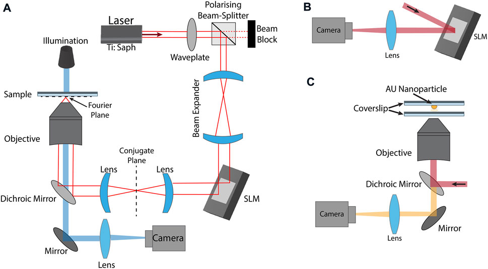
FIGURE 1. (A) Experimental setup for holographic optical tweezers/two-photon-photopolymerisation. A Coherent Mira 900 F femtosecond laser tuned to 780 nm, produces
The same setup (Figure 1A) is used for optical trapping. The trapping beam is produced by the femtosecond laser operating in CW mode. The xy-position of a microsphere is used to quantity optical trap performance, as measured using the CMOS camera. A dilute solution of 3 μm polystyrene microspheres and deionised water are loaded into a sealed sample chamber consisting of two microscope coverslips adhered using double-sided tape.
2.2 Aberration correction technique
The beam can be highly distorted due to the numerous optical elements present in the system, or through imperfections present in the original laser beam and correcting beam aberrations has been shown to be an important step in order to provide the most precise light structure needed for the best operation of 2PP. These aberration corrections are also of upmost importance when printing structures with are hollow or tall (Kelemen et al., 2011).
The correction technique applied here seeks to optimise the beam’s points spread function through interference between distinct modes on an SLM ((Čižmár et al., 2010), (Stilgoe and Rubinsztein-Dunlop, 2021)). In principle, each mode could correspond to a single pixel of the device, although in practice the time to carry out this correction in conjunction with the low light-level reflected makes this not feasible. Therefore the SLM is segmented into sub-regions, where the phase correction for each element is extracted. All elements can be corrected for simultaneously by measuring the intensity variation resulting from interference with a central region of the device where the phase is static throughout the procedure. The phase of every other patch is modulated between 0 and 2π at a specific frequency. Each of these frequencies are chosen to be odd integers, resulting in a unique correlation signal for each region (Stilgoe and Rubinsztein-Dunlop, 2021). What is implemented here is inspired by this work, but easier to implement. Consider the odd frequency correlation of two regions of an SLM that is divided into
where N refers to the total number of SLM regions (patches),
where ϕ(fn) is the phase corresponding each odd-integer frequency mode fn, and ψn is the correction for patch, n.
This method has the benefit of being able to account for all optical aberrations throughout the optical train up until that point, including any from the SLM itself. Although this method was implemented before the microscope objective, the process can be used in-situ at the focus after the objective by using fluorescence signals or reflections from metallic nanoparticles. If required, this process can be repeated where
2.3 Phase retrieval
The practical implementation of the correction outlined in Section 2.2 is provided in Figure 2. We start by sub-diving the SLM into
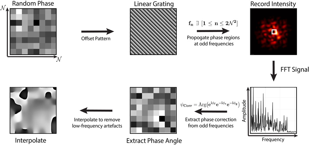
FIGURE 2. Phase retrieval: We start by dividing the SLM into
In our setup, then phase correction is found by using 510 of the 512 available pixels in each row of the device, with a 15 × 15 resolution grid. In principle this grid could be further refined, though improvements are minimal relative to the increased computation time. In Figure 3, we show the beam amplitude as measured at the SLM, reconstructed from the interference signal (a), an interpolated phase correction which optimises the focused beam (b), the uncorrected focused beam in the conjugate plane of the SLM (c), and the corrected zeroth order beam (d). As the result from this correction procedure we can see a vast improvement in the structure of the correcting beam.
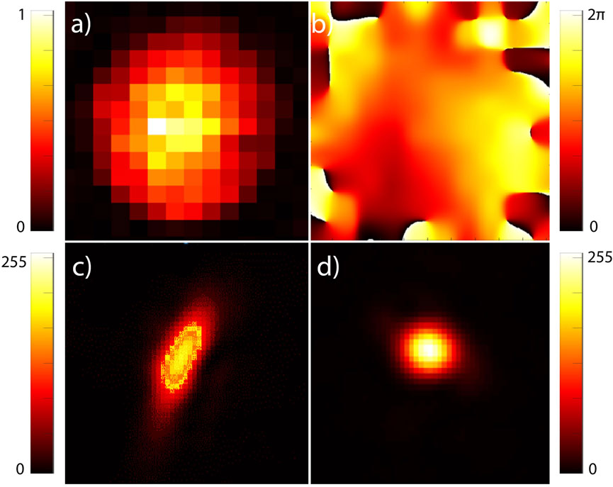
FIGURE 3. (A) Laser beam profile reconstructed from the interference signal using a CCD camera situated in the conjugate plane of the spatial Light Modulator. (B) Found phase correction, as determined in-situ, described in Section 2.4. (C) Uncorrected focused beam in the imaging plane. (D) Corrected, focused beam using phase pattern in (B).
2.4 In-Situ corrections
Phase retrieval is most easily achieved using a camera situated in the conjugate plane of the SLM, as in Figure 1B, although the aberration correction found in this plane likely differs somewhat from the correction required at the objective focus within a sample (Fourier plane). In our case the beam undergoes additional distortions imposed by a dichroic mirror and high-NA objective, which we seek to correct for. To achieve this, the same procedure outlined in Figure 2 is carried out, except the interference signal is instead obtained from gold nanoparticle reflections adhered to a coverslip, shown in Figure 1C. Here, a dilute 75 nm gold nanoparticle solution is dropped onto a microscope coverslip and allowed to dry, adhering the particle to the glass. When measurements are being taken, refractive-index matched immersion oil on both sides of the coverslip to reduce unwanted reflections from the glass. Using an oil-immersion objective means that the correction will not be valid for all distances, for optical trapping in water. However, in practice we observe improvements in beam quality for the practical axial distances used. Alternatively, the use of a water-immersion objective produces a correction for all trapping depths (Čižmár et al., 2010).
3 Results and discussion
We demonstrate the effects of aberration corrected laser foci and its application to enhanced optical trapping and 2PP fabrication. These phase corrections are versatile in respect that they improve symmetry for single displaced trapping sites, while improving uniformity and efficiency when generating many point-like foci, and finally it demonstrates enhanced sharpness and resolution of structured light using complex phase masks.
3.1 Ex-Situ and in-situ optical trap confinement
In order to quantitatively compare the effect of phase corrections on optical trap formation, we observe the 2D position distribution of 3 μm polystyrene trapped microspheres in three instances using the same setup described in Figure 1A with the laser operating in continuous-wave mode. We are able to infer the optical trap structure and symmetry by observing the lateral plane position distributions from a single optical trap displaced from the 0th order with a linear grating. We then perform the same measurements using phase-corrections found in the conjugate and Fourier planes, as shown in Figure 4. Figure 4 shows an increase in optical trap stiffness with ex-situ and in-situ phase corrections, while keeping the laser power constant. Trap stiffness is found from centroid positions (Parthasarathy, 2012) using 5k frames captured at 100 FPS. The 1D optical trap stiffness is found using the equipartition theorem as,
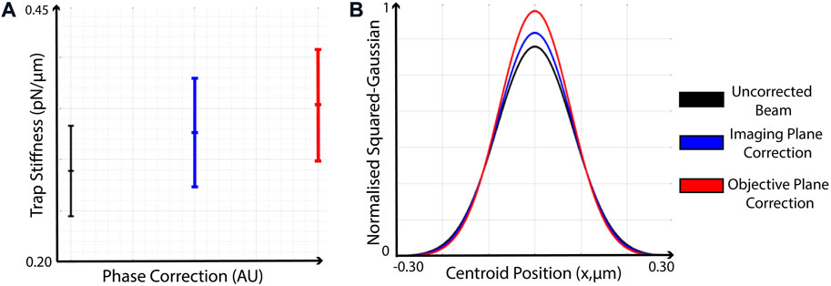
FIGURE 4. Improvement in optical trap stiffness when applying phase corrections in the conjugate and Fourier planes. Both figures are generated using centroid measurements from an optically trapped 3 μm polystyrene particle, using 5k frames captured at 100 FPS. (A) Optical trap stiffness calculated using the uncorrected beam, beam with phase-correction applied as found in the conjugate plane of the SLM, and the corrected beam using in-situ (Fourier plane) phase correction at the focus of the microscope objective. (B) Normalised, Squared-Gaussian fit using from the histograms of particle positions used in (A).
3.2 Imaging plane corrections
Implications of phase-only holographic corrections are clearly evident when observing the conjugate plane of the SLM with a CCD camera, again utilising the experimental configuration shown in Figure 1B. Though this correction will not strictly be the same as that obtained after the microscope objective, it is useful for demonstrating how wavefront distortions affect the focusing of light directly after the diffractive optical element. For this purpose we consider three examples in Figure 5, utilising common patterns in holographic optical trapping systems which are affected by aberrations in different ways.
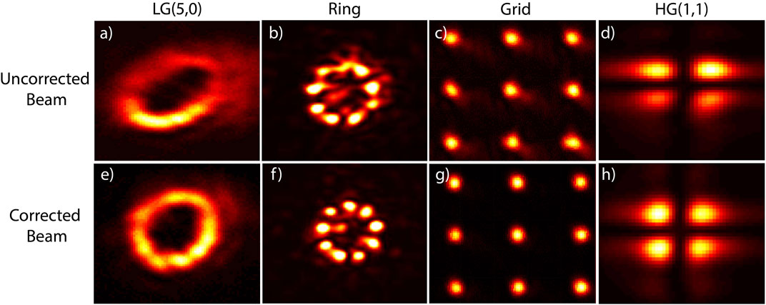
FIGURE 5. Comparison of uncorrected (A–D) and corrected (E–H) beams commonly used in holographic optical tweezers systems. (A,E) Laguerre-Gaussian (LG) beams with a topological charge of
The first beam is a Laguerre-Gauss mode with topological charge
3.3 Aberration corrected 2PP
The aforementioned beam modulation methods are tested with bright-field microscopy images demonstrated in Figures 6A,E shows a Hermite-Gauss (1,1) mode. Figures 6B,F show the letter Q, printed by rapidly loading 50 holograms onto the SLM with 50 ms exposure. This method (Zhang et al., 2014) involves rapidly displaying pre-calculated GS phase patterns with different initially random phases onto the SLM for short periods of time. Using this technique, random variations in intensity are averaged out to produce smooth structures. Figures 6C,G demonstrates a tightly-packed 7 × 7 grid with side length 10 μm. The effect of phase corrections becomes increasingly evident as the number of trapping sites increases, as is clearly seen for this grid where some sites on the lattice are not polymerised at all and others lack uniformity. (d,h) shows the printing of 35 spots on a ring of radius 5 μm in a single pass. Further increasing the number of traps continues to show poor uniformity if phase corrections are not taken into account. Maximising the number of polymerising foci while maintaining uniformity has clear benefits when looking to fabricate many identical structures printed in parallel. Such parallel fabrication can be done either by scanning a nanopositioning stage or applying grating functions to a hologram similar to that used in Figure 6. Similarly, if instead all foci are contributing to one large structure, fabrication time can be reduced for each layer whilst ensuring consistent voxel sizes. Both of these corrections are of paramount importance in practical applications of holographic tweezers as well as in many other areas where structured light is used.
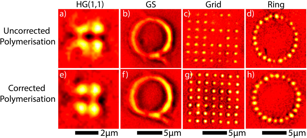
FIGURE 6. False-colour CMOS camera images of polymerised structures printed onto a microscope coverslip using the uncorrected (A–D) and corrected (E–H) beam, utilising the in-situ phase correction shown in Figure 3 (B). (A,E) HG(1,1) mode, (B,F) Letter “Q” fabricated by rapidly displaying 50 phase patterns generated though the Gerchberg-Saxton algorithm. (C,G) Single-pass exposure of a 7 × 7 grid with side length 10μm, generated with the aforementioned optimised Gerchberg-Saxton algorithm (Di Leonardo et al., 2007). (D,H) 35 equidistant foci forming a ring with radius 5μm, fabricated in a single exposure.
In practice, there is a trade-off between the number of foci used for polymerisation and resin exposure time. Naturally, as the number of polymerising sites is increased while maintaining a constant input power, the time required for polymerisation also increases. If many traps are formed close together, long exposure times can sometimes cause nearby resin to be attracted to the focal point, potentially distorting the structure. For reference, the 49 traps polymerised in a single pass in Figure 6C requires 0.8 s exposure with 170 mW average power, as measured immediately before the microscope objective. We find that an optimal trade-off between the number of foci and exposure time, such that we can produce consistently smooth structures, occurs when using 30 foci with an exposure time of 0.2 s, again using an average power of 170 mW.
3.4 Tolerance of photosensitive resin
Tighter confinement of trap foci has also shown to be useful in extending the usable range of the photosensitive resin when considering three distinct phases of the polymer. These are the unpolymerised phase, where the resin is still in liquid state or in a gel state (Odian, 2004), referring to when the branched polymer undergoes partial cross-linking, the desired polymerised state, and the burnt phase, where the polymer visibly breaks down due to high energy, often appearing as though the liquid is bubbling. Although a more tightly confined spot is more intense at the focus, there is less stray light in the immediate vicinity of the trap which may initiate polymerisation. By recording these three phases at a single trapping site whilst varying laser intensity and exposure time, we observe that the polymerised band in a phase diagram shown in Figure 7 is widened. This implies that there is a greater tolerance to polymer breakdown, reducing the probability of inadvertently damaging the structure during fabrication near the polymerisation thresh-hold, which is the optimal operating condition for the highest possible resolution.
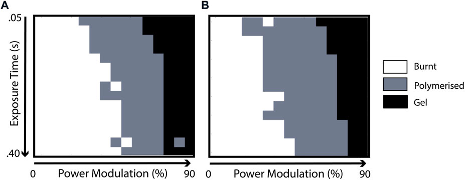
FIGURE 7. Transmitted power and exposure time is varied to polymerise individual voxels of photosensitive resin without (A) and with (B) aberration correction applied.
4 Conclusion
In this work we have demonstrated how applying phase-only aberration corrections in and ex-situ using an SLM improves the performance of versatile applications when using optical tweezers and 2PP implementations. Using scattered light from a gold nanoparticle we find phase corrections which further improve optical trap confinement compared with corrections found in the conjugate plane of an SLM. These corrections are then used to improve the quality of microscopic structures fabricated using complex phase patterns though 2PP. Bright field microscopy reveals clear benefits of applying the correction when utilising many foci by improving diffraction efficiency while simultaneously minimising interference between neighbouring traps. Furthermore we observe greater symmetry in polymerised regions when using HG modes and fabricating arbitrary 2D geometries by rapidly displaying patterns found through Gerchberg-Saxton algorithms. Such corrections are shown to be applicable when reducing the fabrication time of structures is desirable by printing many parallel structures on a grid, or when using many traps to fabricate single large structures.
As the complexity of an optical system increases, each component would impart further aberrations on the beam, making corrections increasingly necessary. A limitation of the in-situ method, however, is that the correction is valid for only a selected trapping depth and cannot be calculated fast enough to be done in real-time. We envisage using this technique to improve optical trap quality and depth in biological samples which require focusing through more complex media.
Data availability statement
The raw data supporting the conclusions of this article will be made available by the authors, without undue reservation.
Author contributions
DA designed and performed experiments and wrote the initial manuscript. AS developed theory and experimental design. AS, TN, and HR-D devised the concept of the investigation. HR-D acquired funding for this work. All authors have contributed to, and edited, the manuscript. All authors have read and agreed to the publication of the manuscript in its’ current form.
Funding
AS, TN, and HR-D acknowledge the support of Australian Research Council Discovery Project number DP180101002 and ARC Centre of Excellence for Engineered Quantum Systems (EQUS, CE170100009). DA acknowledges funding from the Australian Government Research Training Program (RTP) Scholarship.
Conflict of interest
The authors declare that the research was conducted in the absence of any commercial or financial relationships that could be construed as a potential conflict of interest.
Publisher’s note
All claims expressed in this article are solely those of the authors and do not necessarily represent those of their affiliated organizations, or those of the publisher, the editors and the reviewers. Any product that may be evaluated in this article, or claim that may be made by its manufacturer, is not guaranteed or endorsed by the publisher.
References
Agate, B., Brown, C., Sibbett, W., and Dholakia, K. (2004). Femtosecond optical tweezers for in-situ control of two-photon fluorescence. Opt. Express 12, 3011–3017. doi:10.1364/opex.12.003011
Andrews, D. L. (2011). Structured light and its applications: An introduction to phase-structured beams and nanoscale optical forces. Academic Press.
Asavei, T., Loke, V. L. Y., Barbieri, M., Nieminen, T. A., Heckenberg, N. R., and Rubinsztein-Dunlop, H. (2009). Optical angular momentum transfer to microrotors fabricated by two-photon photopolymerization. New J. Phys. 11, 093021. doi:10.1088/1367-2630/11/9/093021
Ashkin, A., Dziedzic, J. M., Bjorkholm, J. E., and Chu, S. (1986). Observation of a single-beam gradient force optical trap for dielectric particles. Opt. Lett. 11, 288. doi:10.1364/OL.11.000288
Born, M., and Wolf, E. (2013). Principles of optics: Electromagnetic theory of propagation, interference and diffraction of light. Elsevier.
Čižmár, T., Mazilu, M., and Dholakia, K. (2010). In situ wavefront correction and its application to micromanipulation. Nat. Photonics 4, 388–394. doi:10.1038/nphoton.2010.85
Di Leonardo, R., Ianni, F., and Ruocco, G. (2007). Computer generation of optimal holograms for optical trap arrays. Opt. Express 15, 1913–1922. doi:10.1364/oe.15.001913
Farsari, M., Filippidis, G., Sambani, K., Drakakis, T. S., and Fotakis, C. (2006). Two-photon polymerization of an eosin y-sensitized acrylate composite. J. Photochem. Photobiol. A Chem. 181, 132–135. doi:10.1016/j.jphotochem.2005.11.025
Galajda, P., Keymer, J., Chaikin, P., and Austin, R. (2007). A wall of funnels concentrates swimming bacteria. J. Bacteriol. 189, 8704–8707. doi:10.1128/jb.01033-07
Gauthier, G., Bell, T. A., Stilgoe, A. B., Baker, M., Rubinsztein-Dunlop, H., and Neely, T. W. (2021). “Dynamic high-resolution optical trapping of ultracold atoms,” in Advances in atomic, molecular, and optical physics (Elsevier), 70, 1–101.
Gauthier, G., Lenton, I., Parry, N. M., Baker, M., Davis, M., Rubinsztein-Dunlop, H., et al. (2016). Direct imaging of a digital-micromirror device for configurable microscopic optical potentials. Optica 3, 1136–1143. doi:10.1364/optica.3.001136
Gerchberg, R. W. (1972). A practical algorithm for the determination of plane from image and diffraction pictures. Optik 35, 237–246.
Jesacher, A., Schwaighofer, A., Fürhapter, S., Maurer, C., Bernet, S., and Ritsch-Marte, M. (2007). Wavefront correction of spatial light modulators using an optical vortex image. Opt. Express 15, 5801–5808. doi:10.1364/oe.15.005801
Ji, S., Li, R., Cai, Z., Pan, D., Yang, L., Hu, Y., et al. (2019). Holographic femtosecond laser integration of microtube arrays inside a hollow needle as a lab-in-a-needle device. Opt. Lett. 44, 5073–5076. doi:10.1364/ol.44.005073
Jones, P. H., Maragò, O. M., and Volpe, G. (2015). Optical tweezers: Principles and applications. Cambridge University Press. doi:10.1017/CBO9781107279711
Kawata, S., Sun, H.-B., Tanaka, T., and Takada, K. (2001). Finer features for functional microdevices. Nature 412, 697–698. doi:10.1038/35089130
Kelemen, L., Ormos, P., and Vizsnyiczai, G. (2011). Two-photon polymerization with optimized spatial light modulator. J. Eur. Opt. Society-Rapid Publ. 6, 11029. doi:10.2971/jeos.2011.11029
Kelemen, L., Valkai, S., and Ormos, P. (2007). Parallel photopolymerisation with complex light patterns generated by diffractive optical elements. Opt. Express 15, 14488–14497. doi:10.1364/oe.15.014488
Knöner, G., Higuet, J., Parkin, S., Nieminen, T. A., Heckenberg, N. R., and Rubinsztein-Dunlop, H. (2006). Two-photon polymerization process for optically driven micromachines. Photonics Des. Technol. Packag. II (SPIE) 6038, 208–216.
Korda, P., Spalding, G. C., Dufresne, E. R., and Grier, D. G. (2002). Nanofabrication with holographic optical tweezers. Rev. Sci. Instrum. 73, 1956–1957. doi:10.1063/1.1455136
Maruo, S., Nakamura, O., and Kawata, S. (1997). Three-dimensional microfabrication with two-photon-absorbed photopolymerization. Opt. Lett. 22, 132–134. doi:10.1364/ol.22.000132
Obata, K., Koch, J., Hinze, U., and Chichkov, B. N. (2010). Multi-focus two-photon polymerization technique based on individually controlled phase modulation. Opt. Express 18, 17193–17200. doi:10.1364/oe.18.017193
Otuka, A. J., Tomazio, N. B., Paula, K. T., and Mendonça, C. R. (2021). Two-photon polymerization: Functionalized microstructures, micro-resonators, and bio-scaffolds. Polymers 13, 1994. doi:10.3390/polym13121994
Parthasarathy, R. (2012). Rapid, accurate particle tracking by calculation of radial symmetry centers. Nat. Methods 9, 724–726. doi:10.1038/nmeth.2071
Reichhardt, C. J. O., and Reichhardt, C. (2017). Ratchet effects in active matter systems. Annu. Rev. Condens. Matter Phys. 8, 51–75. doi:10.1146/annurev-conmatphys-031016-025522
Schizas, C., Melissinaki, V., Gaidukeviciute, A., Reinhardt, C., Ohrt, C., Dedoussis, V., et al. (2010). On the design and fabrication by two-photon polymerization of a readily assembled micro-valve. Int. J. Adv. Manuf. Technol. 48, 435–441. doi:10.1007/s00170-009-2320-4
Stichel, T., Hecht, B., Steenhusen, S., Houbertz, R., and Sextl, G. (2016). Two-photon polymerization setup enables experimental mapping and correction of spherical aberrations for improved macroscopic structure fabrication. Opt. Lett. 41, 4269–4272. doi:10.1364/ol.41.004269
Stilgoe, A. B., and Rubinsztein-Dunlop, H. (2021). Wave characterisation and aberration correction using hybrid direct search. J. Opt. 23, 085602. doi:10.1088/2040-8986/ac094d
Sun, H.-B., and Kawata, S. (2004). Two-photon photopolymerization and 3d lithographic microfabrication. NMR• 3D Analysis• Photopolymerization, 169–273.
Vermeulen, K. C., Wuite, G. J., Stienen, G. J., and Schmidt, C. F. (2006). Optical trap stiffness in the presence and absence of spherical aberrations. Appl. Opt. 45, 1812–1819. doi:10.1364/ao.45.001812
Vizsnyiczai, G., Frangipane, G., Bianchi, S., Saglimbeni, F., Dell’Arciprete, D., and Di Leonardo, R. (2020). A transition to stable one-dimensional swimming enhances e. coli motility through narrow channels. Nat. Commun. 11, 2340–2347. doi:10.1038/s41467-020-15711-0
Ward, J., Auth, D., and Carlson, F. (1971). Lens aberration correction by holography. Appl. Opt. 10, 896–900. doi:10.1364/ao.10.000896
Wulff, K. D., Cole, D. G., Clark, R. L., DiLeonardo, R., Leach, J., Cooper, J., et al. (2006). Aberration correction in holographic optical tweezers. Opt. Express 14, 4170–4174. doi:10.1364/oe.14.004170
Xu, B., Ji, S., Pan, D., Hu, W., Zhu, S., Hu, Y., et al. (2020). Hybrid femtosecond laser fabrication of a size-tunable microtrap chip with a high-trapping retention rate. Opt. Lett. 45, 1071–1074. doi:10.1364/ol.386095
Yang, L., Li, J., Hu, Y., Zhang, C., Lao, Z., Huang, W., et al. (2014). Projection two-photon polymerization using a spatial light modulator. Opt. Commun. 331, 82–86. doi:10.1016/j.optcom.2014.05.051
Zernike, v. F. (1934). Beugungstheorie des schneidenver-fahrens und seiner verbesserten form, der phasenkontrastmethode. physica 1, 689–704. doi:10.1016/s0031-8914(34)80259-5
Keywords: aberration correction, two photon polymerization (2PP), holographic optical tweezers, optical trapping, micro-structures, nanofabriaction, computer generated hologram (CGH), photopolymerisation
Citation: Armstrong DJ, Stilgoe AB, Nieminen TA and Rubinsztein-Dunlop H (2022) Improved two-photon photopolymerisation and optical trapping with aberration-corrected structured light. Front. Nanotechnol. 4:998656. doi: 10.3389/fnano.2022.998656
Received: 20 July 2022; Accepted: 16 September 2022;
Published: 04 October 2022.
Edited by:
Donato Conteduca, University of York, United KingdomReviewed by:
Yan Zhang, Capital Normal University, ChinaDarius Gailevičius, Vilnius University, Lithuania
Copyright © 2022 Armstrong, Stilgoe, Nieminen and Rubinsztein-Dunlop. This is an open-access article distributed under the terms of the Creative Commons Attribution License (CC BY). The use, distribution or reproduction in other forums is permitted, provided the original author(s) and the copyright owner(s) are credited and that the original publication in this journal is cited, in accordance with accepted academic practice. No use, distribution or reproduction is permitted which does not comply with these terms.
*Correspondence: D. J. Armstrong, ZGVjbGFuLmFybXN0cm9uZ0B1cS5lZHUuYXU=