 Connor Moreno
 Aaron Bader1,2
 Paul Wilson
- 1Computational Nuclear Engineering Research Group, Department of Nuclear Engineering and Engineering Physics, University of Wisconsin—Madison, Madison, WI, United States
- 2Type One Energy Group, Madison, WI, United States
The three-dimensional variation inherent to stellarator geometries and fusion sources motivates three-dimensional modeling to obtain accurate results from computational modeling in support of design and analysis of first wall, blanket, and shield (FWBS) systems. Manually constructing stellarator fusion power plant geometries in computer-aided design (CAD) and defining the corresponding fusion source can be cumbersome and challenging. The open-source parametric modeling toolset ParaStell has been developed to automate construction of such geometries in low-fidelity. Low-fidelity modeling is useful during the conceptual phase of engineering design as a means of rapidly exploring the design space of a given device. The modeling capability of ParaStell includes in-vessel components and magnets, for any given stellarator configuration, using a parametric definition and plasma equilibrium data. Furthermore, the toolset automates the generation of detailed, tetrahedral neutron source definitions and DAGMC geometries for use in neutronics modeling. ParaStell assists rapid design iteration, parametric study, and design optimization of stellarator fusion cores. As a demonstration of the design iteration capability, the effect of the three-dimensional parameter space on tritium breeding and magnet shielding is investigated, using the WISTELL-D configuration as a design basis. Blanket and shield thicknesses are varied in three dimensions, using the space available between the plasma edge and magnet coils as a constraint. The corresponding effects on tritium breeding ratio and magnet heating are tallied using the open-source Monte Carlo particle transport code OpenMC. The inclusion of additional and higher-fidelity modeling capabilities is planned for ParaStell’s future, as well as its implementation in machine-driven optimization.
1 Introduction
With nuclear fusion power firmly in a technology development phase and with several types of fusion power plants under investigation, one device that has seen renewed interest in recent years is the stellarator. The stellarator offers distinct advantages over the more developed tokamak concept, particularly inherent steady-state operation and confinement independent of plasma current (Boozer, 2015; Helander et al., 2012). These advantages come with the challenge of geometric complexity, complicating engineering design and manufacturing (Boozer, 2015; Helander et al., 2012). These issues are in part responsible for the lack of development compared to the tokamak. However, more recent advancement in CAD, high-performance computing (HPC), and manufacturing ability has supported a renewed stellarator R&D effort.
Stellarators as fusion power plants are in a conceptual, or even pre-conceptual, design phase. During this period of engineering design, it is useful to explore a device’s design space, iterating over many design configurations while tracking performance and selecting promising design points to investigate more deeply. To this end, lower fidelity modeling is most practical. The reduced detail of low fidelity models accelerates the modeling of design iterations, expediting exploration of the design space. It should be noted, however, that lower fidelity modeling is appropriate only when it produces reasonably accurate performance metrics from computational experiments. In the case of tracking neutronics performance for more global performance metrics, such as TBR or total magnet nuclear heating, modeling small geometric detail is unnecessary and thus such an approach is valid.
A CAD technique that complements low fidelity modeling is parametric modeling. Parametric modeling abstracts a device’s geometry to its principal dimensions. In this manner, a device’s complete geometry can be defined by a reduced set of geometric parameters. This technique can further expedite model production by allowing its automation, while supporting the exploration of a device’s design space as it makes tracking geometric parameters straight-forward.
In the fusion space, the python package Paramak was developed as a low-to-medium fidelity parametric modeling toolset for tokamak FWBS systems (Shimwell et al., 2021). Because it is designed for tokamaks, the toolset assumes toroidal symmetry. The lack of geometric symmetry in stellarators means devices cannot be accurately approximated to lower dimensions, and previous work established the importance of 3-D modeling for stellarator components (Najmabadi et al., 2008). Thus, tools such as Paramak are not appropriate for stellarator design and analysis, and therefore novel modeling approaches are required.
To aid the stellarator R&D effort, the low-fidelity parametric modeling toolset ParaStell has been developed. This toolset allows users to model homogenized in-vessel components and magnets using a parametric definition and plasma equilibrium data. ParaStell is compatible with any stellarator plasma equilibrium, assuming it is in the standard MHD optimization output format with a VMEC (Hirshman and Whitson, 1983) plasma description and coil filament point-locus data.
2 Methods
ParaStell (Moreno et al., 2023) is a platform-independent, open-source python package with primary dependencies in CadQuery (Shimwell, 2023), Coreform Cubit (Coreform Cubit, 2023), CAD-to-DAGMC (Urbanczyk, 2023b), and PyStell-UW (PyStell-UW, 2023). CadQuery is an open-source python package providing parametric 3-D CAD model generation. Coreform Cubit is a commercial software toolset offering meshing and CAD model generation. CAD-to-DAGMC is an open-source Cubit alternative allowing CAD model faceting for neutronics. PyStell-UW is an open-source python package that interprets VMEC data, in addition to data not relevant to this work. Figure 1 demonstrates the flow of data and operations within ParaStell.
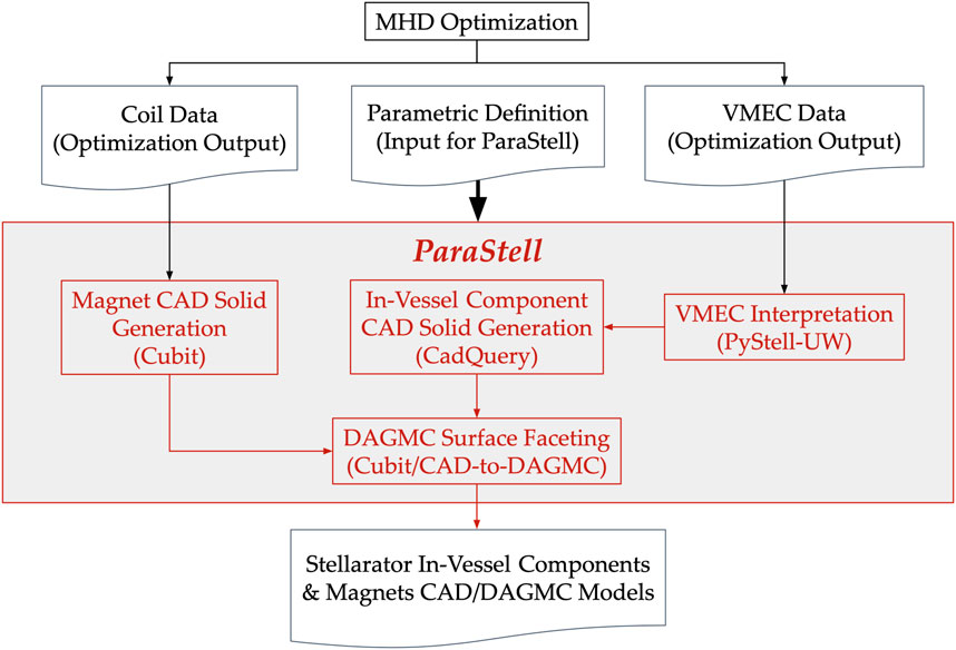
Figure 1. ParaStell data flow.
2.1 Modeling
Stellarator plasmas are described in 3-D flux coordinates (s, θ, ϕ), consisting of the plasma’s normalized closed flux surface (CFS) label s, poloidal parameterizing angle θ, and toroidal angle ϕ. These parametric coordinates are defined on an idealized simple torus, from which the real geometry can be mapped using a transformation defined below. The CFSs are closed surfaces on which the magnetic flux from the magnets is constant. The domain of the CFS label is s = [0, 1], where s = 0 is located at the magnetic axis and s = 1 is the last closed flux surface (LCFS) located at the plasma edge. The poloidal parameterizing angle θ is similar to the poloidal angle in the toroidal coordinate system with domain θ = [0, 2π]. The toroidal angle has domain ϕ = [0, 2π]. Figure 2 illustrates this coordinate system.
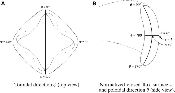
Figure 2. Flux coordinate system illustrated on a four-field-period stellarator plasma. (A) Illustration of flux-coordinate toroidal direction via top view of stellarator plasma. (B) Illustration of flux-coordinate normalized closed flux surface and poloidal direction via side view of stellarator plasma cross-section.
Flux coordinates are transformed to cylindrical coordinates via the Fourier series given in Eq. 1, 2, where Rmn and Zmn are Fourier coefficients corresponding to a specific plasma equilibrium (Lion et al., 2022). Cylindrical coordinates can then be transformed to Cartesian via standard methods.
2.1.1 Plasma and in-vessel components
The plasma and in-vessel components are modeled using CadQuery’s lofting routine to loft a surface across component profiles in differing toroidal planes. To model the plasma, PyStell-UW is used to compute the plasma edge point, located at s = 1, at various locations on the LCFS. Specifically, poloidal profiles are made at different toroidal angles by computing plasma edge points, varying the poloidal angle while keeping the toroidal angle constant. CadQuery’s spline interpolation routine is then used to connect the points into a CAD wire. Subsequently, CadQuery’s lofting routine is invoked to loft across the poloidal profiles to create a CAD solid. Figure 3 illustrates the lofting routine for the plasma.
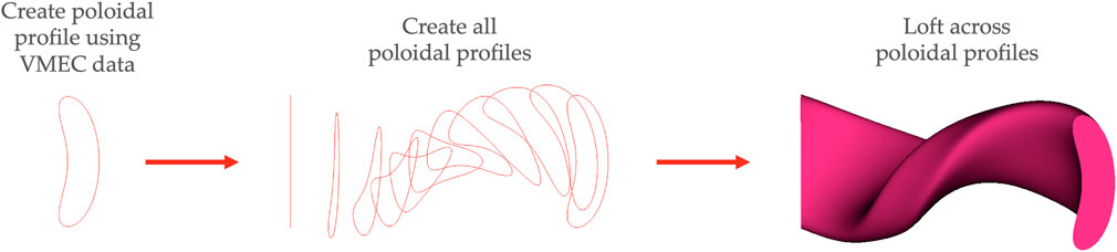
Figure 3. Plasma lofting routine performed for a four-field-period stellarator.
The first wall profile is defined by creating a surface in the same manner as the plasma at a CFS label greater than 1. Although s has a domain defined only on [0,1], PyStell-UW can extrapolate beyond s = 1 using geometric arguments. ParaStell then uses this value to define the first wall location. The plasma is cut from the volume defined by this surface to create a volume for the scrape-off layer (SOL), the region between the plasma LCFS and first wall. Figure 4 demonstrates the cutting routine for an arbitrary stellarator component layer.
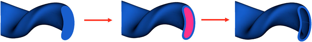
Figure 4. Cutting routine performed on a four-field-period stellarator component.
The in-vessel components are defined by providing a 3-D radial build that assembles a set of 1-D radial builds at each vertex in a user-defined grid of (ϕ, θ) locations. In practice, this data is arranged as a grid of thicknesses for each layer, l, with each element in the grid corresponding to a particular toroidal and poloidal angle, tl(ϕ, θ). Poloidal profile points are offset from the first wall surface in the given toroidal plane. The offset occurs in the direction of the first wall profile’s normal vector at the given (ϕ, θ) pair. The total offset of layer l from the first wall surface, ol(ϕ, θ), is the cumulative sum of component thicknesses at the given (ϕ, θ) pair given in Eq. 3:
These points are connected via spline interpolations and lofted across, similar to the plasma and first wall surfaces. All components interior to the given component are then cut away from this lofted solid to create the component solid. This process is repeated for all components included in the radial build. Figure 5 shows an example poloidal profile of in-vessel components that vary poloidally, with first wall surface normal directions specified at θ = 0°, 90°, 180°, 270°, at a toroidal angle ϕ = 0°. Note that this same process can be used as an alternative way to define the first wall profile, as a grid of offsets from the plasma surface instead of a surface at some s > 1.
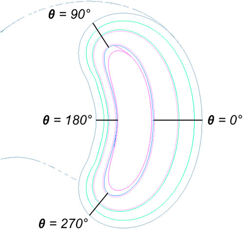
Figure 5. Example poloidal profile of stellarator in-vessel components.
2.1.2 Magnets
For each coil filament, the point-locus data is connected via spline interpolation to create a closed loop. A cross-section, defined by the user as either a parametric rectangle or a parametric circle, is then swept along the filament spline to generate the magnet solid. This process is repeated for all filaments to generate the full set of magnets. It should be noted that if the user defines the toroidal extent of the model to be less than 360°, the magnets will be cut by a wedge spanning the same toroidal extent such that the magnets span the same toroidal extent with partial magnets being included in the model. Figure 6 demonstrates this sweeping routine for the magnets.
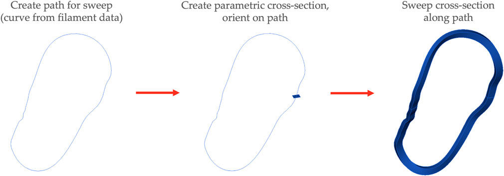
Figure 6. Magnet sweeping routine.
2.1.3 Additional neutronics support
In addition to producing CAD models of the plasma, in-vessel components, and magnets, ParaStell automates the generation of a tetrahedral neutron source mesh for use in neutronics calculations. PyMOAB, the Python interface to the Mesh Oriented dAtaBase (MOAB) (Tautges, 2004), is used to create the mesh. The mesh is generated as a structured mesh with a user-defined number of uniform intervals in each of the dimensions in the flux coordinate system. The resulting mesh has hexahedral elements everywhere except at the magnetic axis where there are wedge elements. This structured mesh in flux space is then transformed to Cartesian space via Eqs 1, 2. Each wedge element is split into three tetrahedra and each hexahedral element is split into five tetrahedra. This splitting and the ordering of vertices for each element is done according to the MOAB canonical numbering system (Tautges, 2010). Figure 7 demonstrates element splitting for wedges and hexahedra.
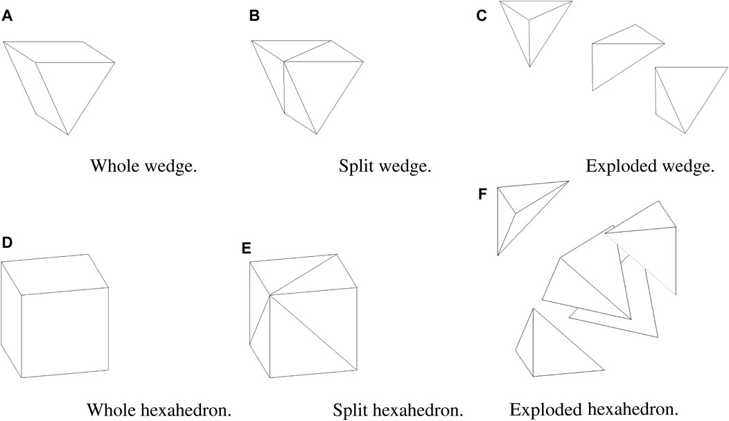
Figure 7. Wedge splitting into three tetrahedra and hexahedron splitting into five tetrahedra. (A) Whole (unsplit) wedge. (B) Wedge split into three tetrahedra. (C) Exploded view of wedge split into three tetrahedra. (D) Whole (unsplit) hexahedron. (E) Hexahedron split into five tetrahedra. (F) Exploded view of hexahedron split into five tetrahedra.
To determine the source strength of each tetrahedron, source strength densities at each tetrahedral vertex are integrated over the tetrahedron using five-node Gaussian quadrature. Source strength density σν at a point in the plasma, which is equivalent to the fusion reaction rate at that point, is only dependent on s. For any plasma equilibrium, σν(s) is given in m−3s−1 by Eq. 4 (Bader et al., 2021)
where n(s) is the ion density in m−3 and T(s) is the plasma temperature in keV.
To use CAD models in neutronics calculations, it is necessary to make use of the validated DAGMC geometry library (Tautges, 2009). DAGMC couples to community-standard Monte Carlo radiation transport codes, using a faceted representation of CAD model surfaces, allowing particle transport directly on CAD models. ParaStell is able to automate the generation of DAGMC neutronics geometries via Coreform Cubit or CAD-to-DAGMC.
2.2 2-D parameter study
To demonstrate ParaStell’s use in design iteration, a 2-D parameter study is performed on the WISTELL-D stellarator configuration. WISTELL-D is a configuration that was adapted from the WISTELL-A configuration (Bader et al., 2020). The size is increased from WISTELL-A such that the average major and minor radii are 10.1 m and 1.5 m, respectively. The volume-average magnetic field is 8.3 T. It is designed to have MHD stability at 3% beta. The configuration is designed to be a baseline configuration for comparing reactor-scale quasihelical stellarators.
Ninety-nine (99) candidate FWBS geometry models are analyzed. For all candidates, the first wall, back wall, and vacuum vessel have fixed, uniform thickness. Across the candidate geometries, the breeder and high-temperature shield (HTS) thicknesses are varied between two archetypical system geometries.
The first archetypical geometry sets the lower bound for total FWBS system thickness and is termed the thin configuration. In this configuration, the breeder and HTS have uniform thickness, and the summed thickness of the two components is determined by the minimum space available between the LCFS and magnets. This minimum spacing is 70 cm, which after taking the first wall, back wall, and vacuum vessel thicknesses into account, leaves 30 cm available to the breeder and HTS. There are 9 variations of this thin configuration, where the percentage of the 30 cm available space allotted to the breeder is varied between 10% and 90%, in 10% increments. The remainder of the space is given to the HTS (e.g., 10% breeder signifies 90% HTS). The fraction of the space consumed by the breeder is the first parametric variable in the 2-variable parametric study.
Practically, a stellarator will take advantage of the space available between the LCFS and magnets to maximize breeding while minimizing radiation effects in the magnets. Thus, the other archetypical geometry sets the upper bound for total FWBS system thickness and is termed the thick configuration. This configuration features a breeder and HTS of non-uniform thickness where the thickness of both of these components varies toroidally and poloidally. After accounting for the first wall, back wall, and vacuum vessel, the minimum space available to the breeder and magnets in this configuration is 30 cm, as in the thin configuration, and the maximum space available is 148.7 cm. Applying the first parametric variable described above, there are 9 variations of this configuration in which the percentage of the available space allotted to the breeder is varied in 10% steps between 10% and 90%, with the remainder given to the HTS.
The second parametric variable in the 2-variable parametric study indicates the percentage of the difference of a given configuration’s total FWBS system thickness between the thin configuration and the thick configuration. This parameter applies at all (ϕ, θ) points. There are 11 sampling points along this dimension of the 2-D parameter space, evenly spaced between 0% (the thin configuration) and 100% (the thick configuration) with 10% steps.
The two dimensions create a grid of 99 total sampling points, eleven variations in the fraction of the available thickness used for the FWBS times nine variations in the fraction of the available space used for breeder vs. HTS. As these parameters are varied, the validated Monte Carlo particle transport code OpenMC (Romano et al., 2015) is used to track tritium breeding and magnet shielding performance. DAGMC and OpenMC have been validated for fusion neutronics applications (Valentine et al., 2022).
In OpenMC, a source mesh with 11 s intervals, 81 θ intervals, and 61 ϕ intervals spanning a single period was used to define the fusion neutron source. For this study, we assume an optimistic performance of the stellarator to simulate the neutronic output of a future power plant. The fusion output is set to 2113 MW by using the profiles for ion density and temperature given in Eqs 5 and 6, respectively (Bader et al., 2021):
Simulations were run using 300,000 total particles, split across 30 batches, with photon production from neutrons and subsequent photon transport enabled. Additionally, survival biasing was enabled. TBR and total magnet nuclear heating were tallied.
Regarding the specifics of the geometry, a single period was modeled using rotational periodic boundary conditions at either end of the period. Figure 8 shows the radial build used in ParaStell to produce the models used in OpenMC, including two layers with variable thickness. The total build thickness, excluding the SOL and magnets, ranged from 70 cm to 188.7 cm. The SOL thickness ranges from 5 cm to 50.7 cm, with a CFS extrapolation of s = 1.2. The magnets are approximated with a circular cross-section 40 cm in diameter. The blanket concept used is dual-coolant lithium-lead and the homogenized material definitions used for each component mirror those in ARIES-CS and are given in Table 1 (El-Guebaly et al., 2008). ARIES-CS is a well-developed, three-period conceptual stellarator fusion power plant, developed in the 2000s and 2010s, that provides reliable engineering parameters for fusion stellarator FWBS systems. Table 2 lists the chemical compositions of the materials given in Table 1. Note that these are estimated and idealistic compositions that ignore impurities, which is suitable for transport calculations but would not be for an activation calculation. RAFM refers to reduced-activation ferritic-martensitic steel, a reduced-activation structural metal commonly proposed for fusion applications (Fernández et al., 2004).
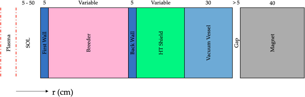
Figure 8. WISTELL-D radial build.
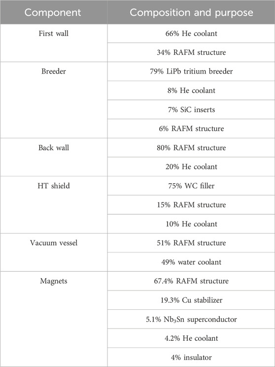
Table 1. WISTELL-D homogenized component material definitions.
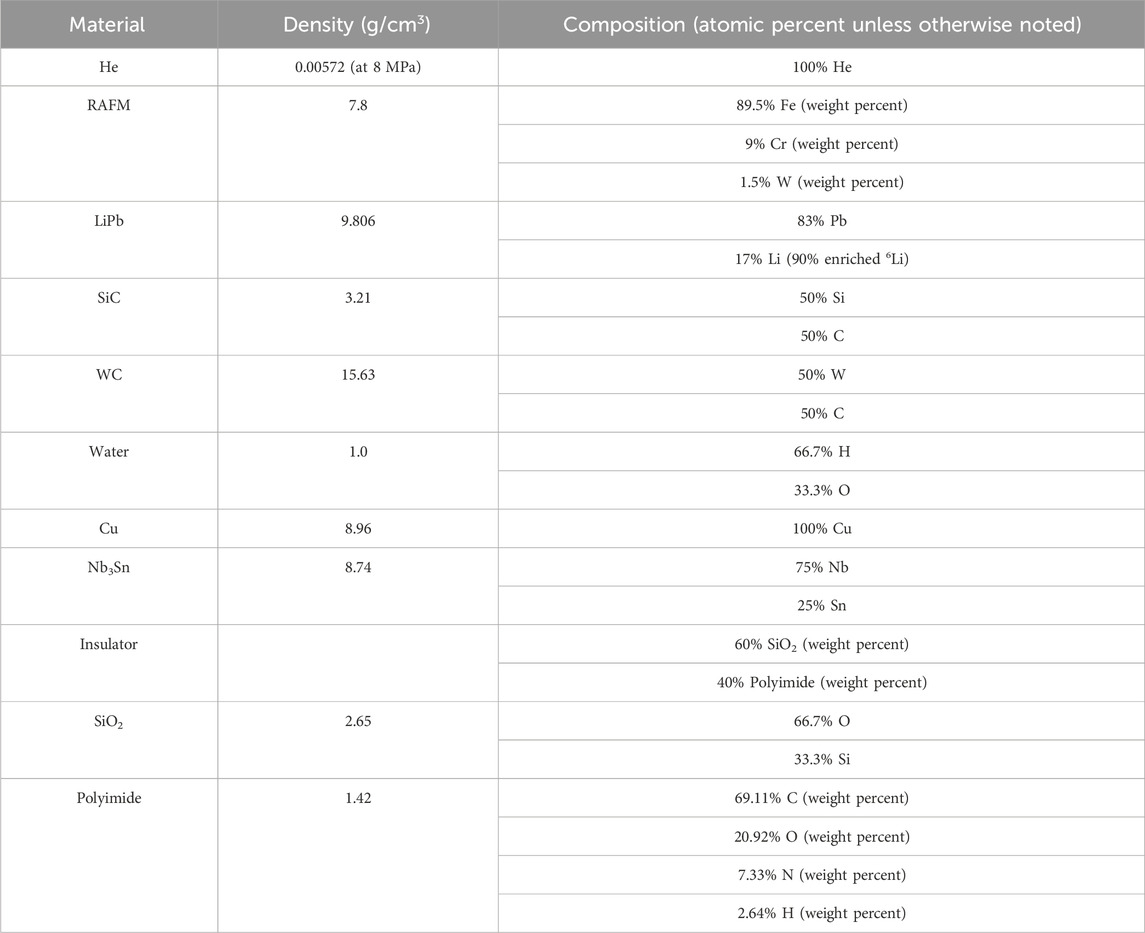
Table 2. Material chemical compositions.
3 Results
3.1 Modeling
Figure 9 presents example CAD geometries generated for three different plasma equilibria via ParaStell. The two-field-period stellarator model features a SOL and in-vessel components of uniform thickness. The three- and four-field-period stellarator models feature SOLs located at s = 1.1 and s = 1.2, respectively, as well as in-vessel components of non-uniform thickness. These equilibria do not have magnet coil filament data available, and thus magnets are not featured in the models. Figure 10 exhibits example source meshes generated for the same three plasma equilibria. The total number of tetrahedra in each source mesh is 921,600.
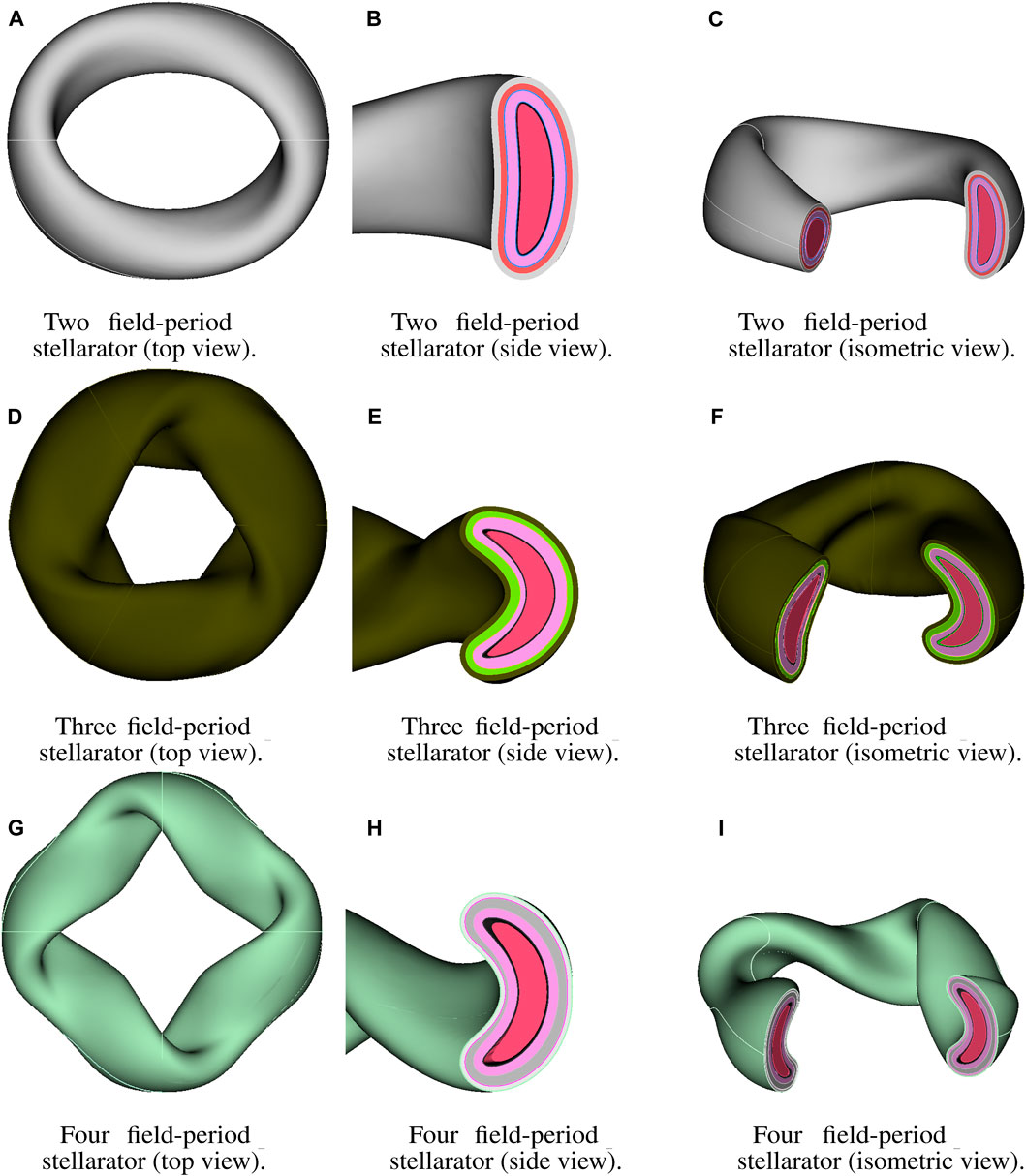
Figure 9. Sample stellarator configurations. (A) Top view of two-field-period stellarator FWBS. (B) Side view of cross-section of two-field-period stellarator FWBS. (C) Isometric view of two-field-period stellarator FWBS with sector removed. (D) Top view of three-field-period stellarator FWBS. (E) Side view of cross-section of three-field-period stellarator FWBS. (F) Isometric view of three-field-period stellarator FWBS with sector removed. (G) Top view of four-field-period stellarator FWBS. (H) Side view of cross-section of four-field-period stellarator FWBS. (I) Isometric view of four-field-period stellarator FWBS with sector removed.
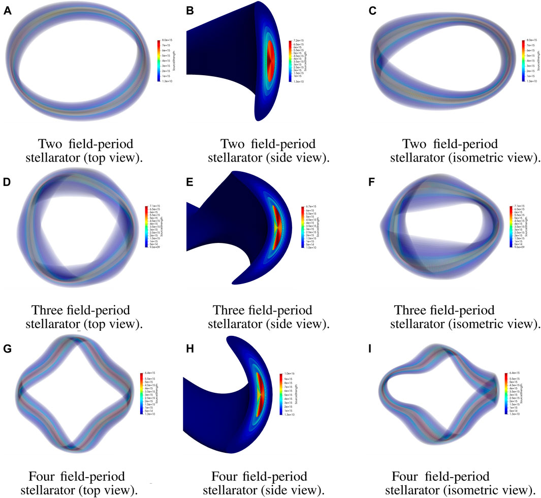
Figure 10. Sample stellarator source meshes. (A) Top view of two-field-period stellarator fusion source mesh. (B) Side view of cross-section of two-field-period stellarator fusion source mesh. (C) Isometric view of two-field-period stellarator fusion source mesh. (D) Top view of three-field-period stellarator fusion source mesh. (E) Side view of cross-section of three-field-period stellarator fusion source mesh. (F) Isometric view os three-field-period stellarator fusion source mesh. (G) Top view of four-field-period stellarator fusion source mesh. (H) Side view of cross-section of four-field-period stellarator fusion source mesh. (I) Isometric view of four-field-period stellarator fusion source mesh.
Figure 11 shows sample WISTELL-D CAD geometries used for the 2-D parameter study. Specifically, the uniform thin and non-uniform thick configurations are shown with a breeder percentage of 60%. Furthermore, Figure 11 shows the source mesh used for each OpenMC run. The total number of tetrahedra in the single-period WISTELL-D source mesh is 230,400.
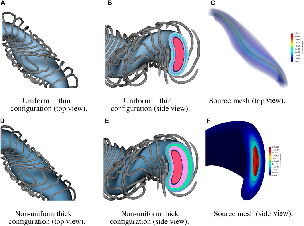
Figure 11. WISTELL-D sample configurations and source mesh. (A) Top view of single-period model of the uniform thin configuration. (B) Side view of single-period model of the uniform thin configuration. (C) Top view of single-period model of WISTELL-D fusion source mesh. (D) Top view of single-period model of the non-uniform thick configuration. (E) Side view of single-period model of the non-uniform thick configuration. (F) Side view of single-period model of WISTELL-D fusion source mesh.
3.2 2-D parameter study
Figure 12 displays the results of the 2-D parameter study. Without investigation into a potential tritium cycle for WISTELL-D, a target value for the TBR of 1.05 was arbitrarily chosen. Comparing the result to this target, it can be seen that the value is met for a range of blanket configurations. No analysis for a cryogenic system to cool the low-temperature superconducting magnets has been performed for WISTELL-D, and thus no total magnet nuclear heating target is available. Therefore, it is of interest to minimize magnet nuclear heating within the design space offering sufficient tritium breeding, and determine whether the corresponding cryogenic load is acceptable.
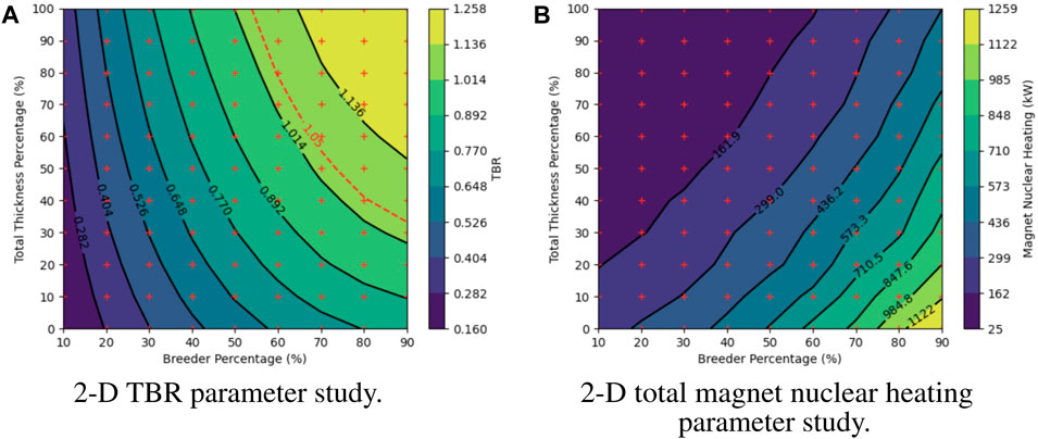
Figure 12. Computational results including TBR and magnet nuclear heating. (A) TBR results for 99 modeled configurations of 2-D parameter study. (B) Total magnet nuclear heating results for 99 modeled configurations of 2-D parameter study.
3.3 Limitations
Plasma equilibrium VMEC information stops immediately at the LCFS boundary and extrapolating from the corresponding Fourier series, given in Eqs 1, 2, beyond s = 1 to define the first wall profile can result in geometric problems. Figure 13A demonstrates such a problem using an example equilibrium at ϕ = 0 with the first wall defined at s = 1.2. Using values of s closer to unity can alleviate such issues, as well as defining the SOL in the radial build, similar to in-vessel component definitions.
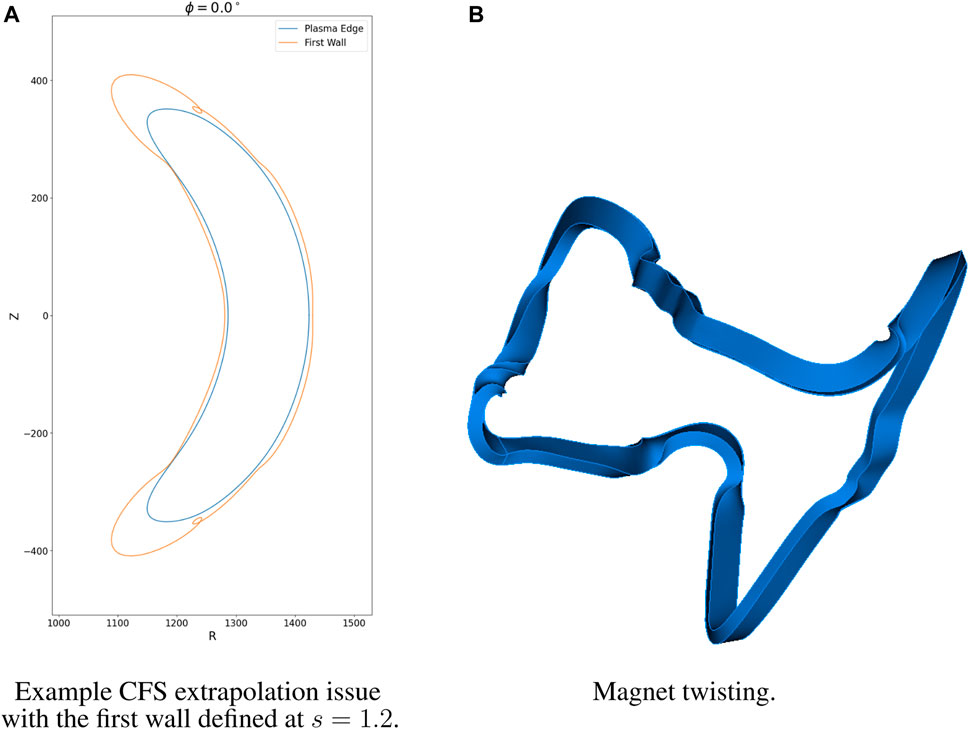
Figure 13. ParaStell modeling limitations. (A) Example of first wall CFS extrapolation issue; note the loops in the computed first wall profile. (B) Example of magnet twisting issue; note the twists in the magnet solid in certain regions of the magnet coil.
It should be noted that using a rectangular cross-section for the magnets can cause CAD modeling issues. Particularly, the sweep operation in CadQuery does not constrain the orientation of the cross-section along the sweeping path. When the magnet filament spline used as the sweeping path is complex, the sweep operation can produce non-physical twists in the magnet solid. Figure 13B illustrates this magnet twisting. Conversely, because circles are radially symmetric, the orientation of the magnet cross-section along the sweeping path does not affect the resultant magnet solid when a circular cross-section is used. For coil sets without complex filament paths, it is likely that a rectangular cross-section would not result in modeling complications.
4 Discussion
It should be reiterated that the design study performed is for the purpose of demonstration, and therefore not enough geometric configurations were modeled for the study to determine a true optimum. Within the design space offering sufficient tritium breeding, of the 99 modeled configurations, the one offering the greatest shielding has a total thickness percentage of 100% and breeder percentage of 60%. For this design point, the TBR is 1.10 and the total magnet nuclear heating is 152.0 kW. The visualization in Figure 12 suggests that there exists a configuration with more shielding and a TBR at the threshold of 1.05, but it was not one of the modeled configurations. For ARIES-CS, the total magnet nuclear heating was calculated to be 12 kW and deemed acceptable for that stellarator configuration as the resultant liquid He cryogenic load was estimated to be 5 MWe (El-Guebaly et al., 2008). Assuming a similar cryogenic system for WISTELL-D with similar efficiency, a total magnet nuclear heating metric of 152.0 kW would correspond to an estimated 63.3 MWe cryogenic load. Compared to an estimated fusion power of about 2113 MW for WISTELL-D, this cryogenic load may be acceptable given a sufficient power plant thermal efficiency. Because this design point exceeds the TBR criterion, one could specify a region of interest about this design point, testing additional design points nearby in order to reduce magnet nuclear heating. That said, it would be of interest to compute peak magnet nuclear heating to be certain that shielding configurations are acceptable.
For WISTELL-D, the magnets exhibiting the greatest nuclear heating are located near the regions of minimum LCFS to coil spacing. This region does not directly receive additional radiation protection by increasing total thickness percentage, as the total thickness of this region does not itself change. Instead, this region only directly receives additional protection by reducing breeder percentage, which increases HTS thickness, or indirectly by increasing total thickness or reducing breeder percentage in neighboring regions. Should no WISTELL-D design point within the tested design space simultaneously satisfy tritium breeding and magnet shielding requirements, it may be necessary to reduce blanket thickness further, using a more efficient blanket concept such as the helium-cooled pebble bed (Zhou et al., 2023). Alternatively, it may be necessary to remove the blanket entirely from regions of minimal LCFS to coil spacing to increase the amount of shielding while keeping the total build thickness high in the regions where the blanket remains.
This 2-D parameter study helps to illustrate the utility of ParaStell in stellarator fusion power plant design, being capable of generating CAD and DAGMC models for a wide range of stellarator configurations. The parametric input and compatibility with any plasma equilibrium facilitates exploration of broad design spaces and suggests great modeling potential. There is no physical benchmark against which to validate the results of the study. However, the low-fidelity modeling featured by ParaStell is intended to assist scoping studies, as evidenced by the 2-D parameter study. Computational benchmarks will be developed in future work involving higher-fidelity modeling.
It is worth noting that ParaStell’s workflows involving in-vessel component CAD model generation and DAGMC model preparation with CAD-to-DAGMC scale indefinitely with cluster computing resources due to their open-source software dependence. However, workflows involving Coreform Cubit, such as magnet CAD model production or DAGMC model generation with Cubit, are limited in scalability by the number of seats on one’s Cubit license. To alleviate this issue, the open-source workflow is being developed to reduce dependence on Cubit. In particular, as there is a Cubit alternative for DAGMC model production, work is being done to develop magnet CAD model generation via CadQuery.
Future development on ParaStell focuses on overcoming current limitations and utility for neutronics and multi-physics calculations. Alternative, robust workflows are under development for the first wall profile and magnet modeling. Some avenues for additional development are first wall surface meshing for neutron wall loading calculations and magnet volume meshing for investigating detailed radiation effects in the magnets. Furthermore, higher fidelity component modeling may be developed to investigate detailed radiation effects in the in-vessel components and for model use in multi-physics calculations. Additionally, coupling ParaStell to machine-driven optimization is planned in order to establish a FWBS neutronics optimization framework for stellarators.
Data availability statement
The raw data supporting the conclusion of this article will be made available by the authors, without undue reservation.
Author contributions
CM: Conceptualization, Data curation, Formal Analysis, Investigation, Methodology, Resources, Software, Validation, Visualization, Writing–original draft. AB: Methodology, Writing–review and editing. PW: Methodology, Writing–review and editing, Conceptualization, Funding acquisition, Project administration, Resources, Supervision.
Funding
The author(s) declare that financial support was received for the research, authorship, and/or publication of this article. This project was funded by DoE Project DE-SC0017122 and the AOF/GERS fellowship at the University of Wisconsin—Madison.
Acknowledgments
The authors would like to acknowledge the INES Fusion group and Center for High Throughput Computing (Center for High Throughput Computing, 2006) at the University of Wisconsin—Madison for assistance with this project.
Conflict of interest
AB is currently an employee of Type One Energy Group. PW is the principal investigator of a project funded by Type One Energy Group, at the University of Wisconsin—Madison, where the open source software detailed in this manuscript will be used as a tool.
The remaining author declares that the research was conducted in the absence of any commercial or financial relationships that could be construed as a potential conflict of interest.
Publisher’s note
All claims expressed in this article are solely those of the authors and do not necessarily represent those of their affiliated organizations, or those of the publisher, the editors and the reviewers. Any product that may be evaluated in this article, or claim that may be made by its manufacturer, is not guaranteed or endorsed by the publisher.
References
Bader, A., Anderson, D., Drevlak, M., Faber, B., Hegna, C., Henneberg, S., et al. (2021). Modeling of energetic particle transport in optimized stellarators. Nucl. Fusion 61, 116060. doi:10.1088/1741-4326/ac2991
Bader, A., Faber, B. J., Schmitt, J. C., Anderson, D. T., Drevlak, M., Duff, J. M., et al. (2020). A new optimized quasihelically symmetric stellarator. J. Plasma Phys. doi:10.48550/arXiv.2004.11426
Boozer, A. H. (2015). Stellarator design. J. Plasma Phys. 81, 515810606. doi:10.1017/S0022377815001373
Center for High Throughput Computing (2006). Center for high Throughput computing. Madison, WI: Center for High Throughput Computing. doi:10.21231/GNT1-HW21
Coreform Cubit (2023). Coreform Cubit (version 2023.11) [computer software]. Orem, UT: Coreform LLC.
El-Guebaly, L., Wilson, P., Henderson, D., Sawan, M., Sviatoslavsky, G., Tautges, T., et al. (2008). Designing ARIES-CS compact radial build and nuclear system: neutronics, shielding, and activation. Fusion Sci. Technol. 54, 747–770. doi:10.13182/FST54-747
Fernández, P., Lancha, A. M., Lapeña, J., Serrano, M., and Hernández-Mayoral, M. (2004). Reduced activation ferritic/martensitic steel eurofer 97 as possible structural material for fusion devices. metallurgical characterization on as-received condition and after simulated services conditions. Tech. Rep. CIEMAT.
Helander, P., Beidler, C. D., Bird, T. M., Drevlak, M., Feng, Y., Hatzky, R., et al. (2012). Stellarator and tokamak plasmas: a comparison. Plasma Phys. Control. Fusion 54, 124009. doi:10.1088/0741-3335/54/12/124009
Hirshman, S. P., and Whitson, J. C. (1983). Steepest descent moment method for three-dimensional magnetohydrodynamic equilibria. Tech. rep. Oak Ridge, TN: Oak Ridge National Laboratory.
Lion, J., Warmer, F., and Wang, H. (2022). A deterministic method for the fast evaluation and optimisation of the 3D neutron wall load for generic stellarator configurations. Nucl. Fusion 62, 076040. doi:10.1088/1741-4326/ac6a67
Moreno, C., Wilson, P., Weinstein, E., and Pflug, E. (2023). ParaStell [computer software]. Madison, WI: Computational Nuclear Engineering Research Group.
Najmabadi, F., Raffray, A. R., Abdel-Khalik, S. I., Bromberg, L., Crosatti, L., El-Guebaly, L., et al. (2008). The ARIES-CS compact stellarator fusion power plant. Fusion Sci. Technol. 54, 655–672. doi:10.13182/FST54-655
Romano, P., Horelik, N., Herman, B., Nelson, A., Forget, B., and Smith, K. (2015). OpenMC: a state-of-the-art Monte Carlo code for research and development. Ann. Nucl. Energy 82, 90–97. doi:10.1016/j.anucene.2014.07.048
Shimwell, J., Billingsley, J., Delaporte-Mathurin, R., Morbey, D., Bluteau, M., Shriwise, P., et al. (2021). The Paramak: automated parametric geometry construction for fusion reactor designs. F1000Research 10, 27. doi:10.12688/f1000research.28224.1
Tautges, T. (2004). MOAB: a mesh-oriented database. Tech. rep. Albuquerque, NM: Sandia National Laboratories.
Tautges, T. (2009). “Acceleration techniques for direct use of CAD-based geometries in Monte Carlo radiation transport,” in International conference on mathematics, computational methods and reactor physics (American Nuclear Society).
Tautges, T. (2010). Canonical numbering systems for finite-element codes. Int. J. Numer. Methods Biomed. Eng. 26, 1559–1572. doi:10.1002/cnm.1237
Urbanczyk, A. (2023b). CadQuery. Parametric Products Intellectual Holdings LLC. (Version 2.3.1) [Computer software].
Valentine, A., Berry, T., Bradnam, S., Hagues, J., and Hodson, J. (2022). Benchmarking of emergent radiation transport codes for fusion neutronics applications. Fusion Eng. Des. 180, 113197. doi:10.1016/j.fusengdes.2022.113197
Keywords: fusion, stellarator, parametric modeling, radial build, tritium breeding, magnet heating
Citation: Moreno C, Bader A and Wilson P (2024) ParaStell: parametric modeling and neutronics support for stellarator fusion power plants. Front. Nucl. Eng. 3:1384788. doi: 10.3389/fnuen.2024.1384788
Received: 10 February 2024; Accepted: 06 March 2024;
Published: 04 April 2024.
Edited by:
Arkady Serikov, Karlsruhe Institute of Technology (KIT), GermanyReviewed by:
Evgeny Ivanov, Institut de Radioprotection et de Sûreté Nucléaire, FranceMark David DeHart, Idaho National Laboratory (DOE), United States
Copyright © 2024 Moreno, Bader and Wilson. This is an open-access article distributed under the terms of the Creative Commons Attribution License (CC BY). The use, distribution or reproduction in other forums is permitted, provided the original author(s) and the copyright owner(s) are credited and that the original publication in this journal is cited, in accordance with accepted academic practice. No use, distribution or reproduction is permitted which does not comply with these terms.
*Correspondence: Connor Moreno, Y2Ftb3Jlbm9Ad2lzYy5lZHU=