1 Introduction
The fluorescence properties of an atomic dipole depend primarily on the so-called local density of states of the electromagnetic (EM) field, i.e., on the number of EM mode decay channels available at the same location (van Tiggelen and Kogan, 1994; Sprik et al., 1996; Kwadrin and Koenderink, 2013). For example, inside a homogeneous dielectric medium with refractive index n, the spontaneous decay rate of an atomic dipole equals (Glauber and Lewenstein, 1991; Scheel et al., 1999)
to a very good approximation, where denotes the corresponding free space decay rate. However, deriving the local density of states of the EM field in more complex scenarios, which involves the calculation of the imaginary parts of the dyadic Green’s function (Novotny and Hecht, 2006; Scheel and Buhmann, 2008; Bennett and Buhmann, 2020; Stourm et al., 2020), can be computationally challenging. Although such calculations can aid the design of photonic devices, they do not provide much physical intuition.
Taking a different approach, Carniglia and Mandel (Carniglia and Mandel, 1971) modeled semi-transparent mirrors by only considering stationary photon modes which contain incoming as well as reflected and transmitted contributions. Their so-called triplet modes depend on reflection and transmission rates and are a subset of the free space photon modes of the EM field. Unfortunately, this approach can result in the prediction of unphysical interference effects when modeling light approaching a mirror from both sides (Zakowicz, 1995). If one wants to avoid such interference problems, adjustments have to be made (Khosravi and Loudon, 1991; Creatore and Andreani, 2008), for example by doubling the usual Hilbert space of the quantised EM field in the presence of a semi-transparent mirror (Furtak-Wells et al., 2018). However, this immediately raises the question where the doubling of the Hilbert space comes from. For a detailed discussion of this question see a recent paper by Southall et al. (2021) which models two-sided semi-transparent mirrors with the help of locally-acting mirror Hamiltonians and a recent paper by Hodgson et al. (2021) which quantises the electromagnetic field in position space.
In the following we use the quantum mirror image detector method by Furtak-Wells et al. (2018) to obtain the basic observables of the quantised EM field in the presence of a mirror-coated dielectric interface. This method maps light scattering in the presence of a two-sided semitransparent mirror onto two analogous free space scenarios. More concretely, in our model, we choose an initial time and use one Hilbert space (labeled a) to describe the EM field on the right and another one (labeled b) to describe the EM field on the left hand side of the mirror interface. For times , we assume that state vectors evolve simply as they would in free space. To identify the electric field amplitude seen by a detector at a certain position and at a given time t in the experimental setup in Figure 1, we notice that this amplitude is a superposition of electric field amplitudes seen in two corresponding free space scenarios. To construct the electric field observable for the above experimental setup, we sum up the signals seen by the original detector and a mirror image detector after placing them at the right positions. Doubling the Hilbert space of the EM field and distinguishing two different types of photons, namely a and b photons, helps to ensure that wave packets which never meet in real space do not interfere in our model.
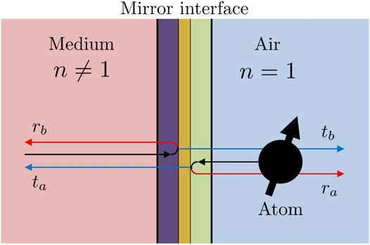
As illustrated in Figure 1, the experimental setup which we consider here consists of a dielectric medium with refractive index , a mirror coating and air with refractive index next to the coating. The possible absorption of light in the mirror interface, which may consist of different layers and may contain different materials, is explicitly taken into account. However, for simplicity, we only consider coherent light absorption and assume that incoming wave packets do not lose their coherence properties when passing through the interface. In this case, there is a linear relation between incoming and outgoing electric field amplitudes which allows us to characterise the mirror interface by (real) electric and magnetic field reflection and transmission rates , , , and . Moreover, the complex amplitudes of electric field vectors accumulate phase factors , …, upon reflection and transmission. The indices a and b refer to light approaching the mirror from the left and from the right hand side, respectively.
In the absence of losses, energy is conserved and Stokes relation implies that the reflection rates for both sides of the mirror interface are the same . In addition, the phases obey certain conditions (Degiorgio, 1980; Zeilinger, 1981). However, suppose losses are taken into account and the absorption rate for light approaching the reflecting layer of the mirror interface from the left is much higher than the absorption rate for light approaching from the right. In this case, the reflection rate is much smaller than , even for a symmetric reflecting layer, and Stokes relation no longer applies. Instead, for mirror interfaces with coherent light absorption, we have (Monzón and Sánchez-Soto, 1995; Barnett et al., 1998; Uppu et al., 2016). In the literature, interfaces with this property are usually referred to as asymmetric mirrors, since they break the forward-backward scattering symmetry of conventional semi-transparent mirrors (Schwanecke et al., 2008; Plum et al., 2009; Zhukovsky et al., 2009; Tumkur et al., 2012; Xu and Lezec, 2014; Kenanakis et al., 2015; Filonov et al., 2018). An alternative way of breaking the symmetry of ideal mirrors, i.e., without the introduction of absorbing layers, is to use surface roughness. Suppose, the reflecting layer is very smooth and highly-reflecting on one side but diffracts light on the other, then we also have .
In the following, we construct the observables of the quantised EM field near a mirror-coated interface with coherent light absorption. To correctly normalise these observables, we demand locality and assume that the spontaneous decay rate of a test atom at a relatively large distance x from the reflecting surface equals its free space value. The spontaneous atomic decay rates near highly-reflecting mirrors (Morawitz, 1969; Stehle, 1970; Milonni and Knight, 1973; Arnoldus and George, 1988; Drabe et al., 1989; Meschede et al., 1990; Amos and Barnes, 1997; Matloob, 2000; Beige et al., 2002; Dorner and Zoller, 2002) and near dielectric media with and without losses (Carniglia and Mandel, 1971; Wylie and Sipe, 1984; Khosravi and Loudon, 1991; Snoeks et al., 1995; Yeung and Gustafson, 1996; Urbach and Rikken, 1998; Xu et al., 2004; Wang et al., 2005; Creatore and Andreani, 2008; Eberlein and Zietal, 2012; Falinejad and Ardekani, 2019) have already been studied extensively in the literature and theoretical predictions are generally in very good agreement with experimental findings (Drexhage, 1970; Chance et al., 1975a; Eschner et al., 2001; Creatore et al., 2009). Like these papers, we ignore interactions of the atomic dipole with the quantum matter of the mirror surface. Instead we assume here that the test atom and the atoms inside the mirror surface are strongly detuned. For simplicity, we also neglect the angle-dependence of reflection rates.
Despite taking an alternative approach, our results are in good agreement with previous results. In addition, our approach allows us to model scenarios which are not as easily accessible using alternative approaches. For example, the main difference between the setup considered in Ref (Furtak-Wells et al., 2018) and the setup which we consider here is the presence of a dielectric with on the left hand side of the interface. The main difference between Ref (Creatore and Andreani, 2008) and our calculations is that we allow for arbitrary mirror coatings, including asymmetric mirrors and mirrors with coherent light absorption.
This paper comprises five sections. In Section 2 we quantise the EM field in a homogenous medium with a refractive index by mapping this situation onto an analogous scenario with . Section 3 covers the quantisation of the EM field in the presence of a mirror-coated interface using the mirror image detector method. In Section 4 we determine the missing normalisation factors of electric and magnetic field amplitudes by calculating the spontaneous emission rate of a test atom. Lastly, Section 5 contains a summary of our findings.
2 The Quantised Electromagnetic Field Inside a Dielectric Medium
The purpose of this section is to obtain the Hamiltonian and the electric and magnetic field observables of the quantised EM field inside a dielectric medium with refractive index n. To do so, we relate its properties to the properties of the quantised EM field in an analogous free space scenario.
2.1 Maxwell’s Equations
Our starting point is classical electrodynamics. In a dielectric medium with permittivity ε and permeability μ and in the absence of any charges and currents, Maxwell’s equations state that (Stratton, 1941)
Here and denote electric and magnetic field vectors at positions and times t. Moreover, we know that the energy of the EM field inside the dielectric medium equals
As an example, we now have a closer look at horizontally polarised light which propagates along the x-axis. In this case, consistency with Maxwell’s equations and with the right hand rule of classical electrodynamics requires that and for wave packets traveling in the positive x direction. Moreover, , and for wave packets traveling in the negative x direction. Substituting these vectors into Eq. 2, they reduce to the differential equations
where the minus and plus signs correspond to different directions of propagation. The solutions of these equations are wave packets which travel at the speed of light . Analogous equations apply for vertically-polarised light traveling along the x axis and for light traveling in other directions.
A special example of a dielectric medium is air with and . In the following, we denote the corresponding field vectors by and . Using this notation, a closer look at Eq. 4 implies the equivalency relations
with the refractive index, as usual, defined as
For air, we simply have . Eq. 5 guarantees that and solve Maxwell’s equations in a dielectric medium when and solve Maxwell’s equations in air.
One difference between electric and magnetic field solutions in a dielectric medium and in air is a re-scaling of field vector amplitudes. Here the factors on the right hand side of Eq. 5 have been chosen such that in Eq. 3 and the energy of the EM field in air,
are the same,
Moreover, on the right hand side of Eq. 5 there is a re-scaling of the position vector . Inside the medium, light travels a shorter distance in the same amount of time but electric and magnetic field amplitudes still oscillate locally at the same rate (Stratton, 1941; Griffiths, 1962).
2.2 Field Quantisation in Air
Wave-particle duality suggests that the EM field is made up of particles, i.e., photons (Bennett et al., 2016). In the case of light propagation in three dimensions, we characterise each photon by its polarisation λ and its wave vector k. Moreover, we know from experiments that a photon with wave vector has the energy with and . Hence the Hamiltonian of the quantised EM field can be written as
where with the bosonic commutator relation denotes the annihilation operator of photons in the mode. Consistency with classical electrodynamics (c.f. Eq. 7) requires that this Hamiltonian coincides, up to a constant, with the observable
where and denote the electric and magnetic field free space observables. Hence both observables are linear superpositions of photon annihilation and creation operators. Demanding consistency with Maxwell’s equations and taking the above field Hamiltonian into account, they can be shown to equal (Bennett et al., 2016)
with and . Here denotes a polarization vector with and . The normalisation factors in Eq. 11 have been chosen such that Eqs 9, 10 differ only by a constant term with no physical consequences.
2.3 Field Quantisation in a Dielectric Medium
To obtain the electric and magnetic field observables and inside a dielectric medium, we now map the dynamics of wave packets inside the medium onto analogous free-space dynamics. In other words, we quantise the EM field in the dielectric medium in terms of free space photons. To do so, we employ the equivalency relations in Eq. 5 which imply that
with and given in Eq. 11. From Eq. 7 we see that the energy observable of the EM field in a dielectric medium equals
Using this equation, one can show that the EM field Hamiltonian of the dielectric medium and in Eq. 9 are the same,
as suggested by Eq. 8. In our description, a photon of frequency ω has the energy in the medium and in free space. The only expectation value that changes when we consider a wave packet of light inside a dielectric medium instead of considering the same quantum state in free space are its electric and magnetic field expectation values. Our ability to describe the dielectric medium with the help of free space observables becomes important in the next section, when we quantise the EM field in the presence of a mirror-coated dielectric medium.
3 The Quantised Electromagnetic Field in the Presence of a Mirror-Coated Interface
To determine the field Hamiltonian of the quantised EM field in Figure 1, we only consider free space photons traveling in air. As usual, we characterise each photon by its polarisation λ and by its wave vector and assume that its energy equals with . However, as mentioned already in the Introduction, in the presence of the mirror interface, we need to double the Hilbert space of the quantised EM field. In the following, we therefore consider two Hilbert spaces which we label a and b and which describe light on the right and light on the left hand side of the mirror surface, respectively, at a given time . Describing both sides separately helps us later on to identify how field excitations contribute to local electric and magnetic field observables (Furtak-Wells et al., 2018). Hence equals
where and are bosonic annihilation operators with and . Next we derive the corresponding electric field observable .
3.1 Highly-Reflecting Mirrors
However, for simplicity, we first have a closer look at a highly-reflecting mirror. In this case, an incoming wave packet changes its direction of propagation upon reaching the interface such that its angle of incidence equals its angle of reflection. Suppose the mirror is placed in the plane. In this case, the y and the z component of the electric field vectors of the incoming light accumulate a minus-sign upon reflection to ensure that they remain orthogonal to the direction of propagation. Now suppose a detector measures the electric field amplitude at a position in the experimental setup shown in Figure 1. Then the mirror image method of classical electrodynamics (Furtak-Wells et al., 2018) suggests that the electric field seen by the detector equals the electric field seen by a detector at the same location minus the electric field seen by a mirror image detector at in free space, i.e., without the mirror interface present. More concretely, the electric field observable equals
if we assume that the a and the b photons evolve as they would in air. Here denotes the Heaviside step function
and the tilde indicates that a minus sign has been added to the x component of the respective vector. Moreover, and are normalisation constants, can be found in Eq. 11 and can be obtained from Eq. 12 by replacing the operators in this equation with . Notice that the right hand side of Eq. 16 is a superposition of operators whose expectation values evolve as predicted by Maxwell’s equations in a dielectric medium and in air, respectively. Hence the observable is automatically consistent with Maxwell’s equations on both sides of the mirror interface, independent of what values we assign later on to and .
As mentioned already above, the constants and in Eq. 16 are normalisation factors. In the next section, we determine them by demanding that the spontaneous decay rate of an atom in the presence of the mirror surface simplifies for large atom-mirror distances to or to , respectively,
As we shall see below, doing so we find that for highly reflecting mirrors. Interpreting this result is not straightforward. As pointed out already in Ref. (Furtak-Wells et al., 2018), for the experimental setup shown in Figure 1, the mirror Hamiltonian in Eq. 15 does not coincide with the observable for the energy of the quantised EM field left and right from the mirror interface. The expectation values of the former are in general larger than the expectation values of the latter. Some of the energy of the system is stored inside the mirror interface which makes it difficult to normalise the electric field observable in Eq. 16 correctly.
3.2 Mirror-Coated Dielectric Media
To obtain the electric field observable in the presence of a two-sided semi-transparent mirror, we need to superimpose the electric field observables of the corresponding free-space scenarios such that any incoming wave packets evolve eventually into superpositions of reflected and transmitted wave packets with their amplitudes accordingly re-scaled. Taking this into account and generalising Eq. 16 as described in Ref. (Furtak-Wells et al., 2018), we find that
As before, the superscripts and are used here to distinguish light originating from the left and from the right hand side of the mirror interface, respectively. At , only the first and the fourth terms in Eq. 19 contribute to the electric field observable . The remaining terms in Eq. 19 describe the electric field contributions of wave packets which have either been reflected by or transmitted through the mirror interface. The factors in front of those terms are the relevant reflection and transmission rates. Finally, phases have been added to describe the phase shifts that the complex electric field amplitudes experience when in contact with the mirror interface. These additional parameters depend on the physical properties of the mirror coating in Figure 1.
In the absence of absorption, energy conservation implies . Moreover the phases have to obey certain conditions (Degiorgio, 1980; Zeilinger, 1981). However, in the presence of coherent light absorption within the mirror surface, and are in general not the same and the phases and rates in Eq. 19 can assume a wide range of different values (Monzón and Sánchez-Soto, 1995; Barnett et al., 1998; Uppu et al., 2016). Suppose all light approaching the reflecting layer of the mirror interface from the left is absorbed, while light approaching from the right reaches the reflecting layer and some of it is turned around. In this case, we have , while . Since absorption is uncontrolled in many practical situations, reflection rates and are in general not the same.
4 Atomic Decay Rates in the Presence of a Mirror Interface
In this section, we finally determine the normalisation constants and in Eq. 19 by deriving the spontaneous decay rate of a two-level atom in the presence of a mirror-coated dielectric interface as a function of the atom-mirror distance . We then demand that this rate simplifies to its well-known free space values for large atom-mirror distances (cf. Eq. 18).
4.1 Derivation
As usual in quantum optics, we describe the dynamics of a two-level atom with ground state and excited state by a master equation in Lindblad form (Stokes et al., 2012). In the absence of any external interactions, like laser excitation, and in the interaction picture with respect to the free energy of the atom, its density matrix is known to evolve according to the differential equation
with and . The last term in this equation equals (Stokes et al., 2012; Furtak-Wells et al., 2018)
up to terms in second order in . Here denotes a relatively short time interval with and is the Hamiltonian of the atom-field system in the interaction picture.
For example, for an atomic dipole inside a dielectric medium with refractive index n, the above interaction Hamiltonian equals (Stokes et al., 2012)
in the usual dipole and rotating wave approximations and with respect to the free energy of the atom and the quantised EM field near the mirror interface. Here e is the charge of a single electron, denotes the complex atomic dipole moment and . Moreover, is the energy difference between the ground and the excited state of the atom. Substituting Eq. 22 into Eq. 21, proceeding as usual (Stokes et al., 2012; Furtak-Wells et al., 2018) and evaluating the above integrals, we find that the spontaneous decay rate of an atom inside a dielectric medium equals
For and , simplifies to the free space decay rate of an atomic dipole in air,
It must be noted that in most dielectric media, μ and are very similar (Griffiths, 1962). Assuming that and combining the definition of the speed of light in air and in a medium with Eq. 6, we obtain Eq. 1. In this case, and differ only by a factor n (Scheel et al., 1999).
To derive the interaction Hamiltonian for the experimental setup shown in Figure 1, we notice that it consists of a dielectric medium with mirror coating and an atom at a position in front of the interface. Hence, in the Schrödinger picture, its Hamiltonian is of the form
Here describes the energy of the atom and denotes the energy of the EM field in the presence of an optical interface which can be found in Eq. 15. Moreover, describes the atom-field interaction and equals in the usual dipole approximation (Stokes et al., 2012). Here equals the electric field observable in Eq. 19 at the position of the atom and with denoting the complex atomic dipole moment with . Transforming into the interaction picture with respect to the free Hamiltonian yields the interaction Hamiltonian . Combining Eqs 11, 19, and applying the rotating wave approximation, one can show that this Hamiltonian equals
for an atomic dipole in front of a mirror-coated dielectric medium (cf. Figure 1).
To calculate its spontaneous decay rate , we substitute Eq. 26 into the right hand side of Eq. 21. Doing so one can show that
Before performing any time integrations, we substitute and and notice that the time integrals
are independent of t and always real. Moreover we know that and therefore also almost all are much larger than . Hence we can safely assume that
up to an imaginary part which does not contribute to later integrals. To perform the remaining integration we use polar coordinates and introduce the vectors
with , resulting in
Using the above equations and performing time and frequency integrations, while denoting the atom-mirror distance by x such that , on can now show that
with . Next we perform the φ integration, substitute and use the relation to obtain the integral
with . Finally also performing the u integration in Eq. 4.1, we obtain the spontaneous decay rate
for . Here denotes the relative overlap of the normalised atomic dipole moment vector with the x axis. For , the atomic dipole aligns parallel to the mirror interface, while it aligns in a perpendicular fashion when . An equivalent expression for can be derived for the case . The result is the same as in Eq. 34 but with the subscripts a and b interchanged and with and replaced by and , respectively. The above calculations are well justified, as long as the atom-mirror distance is not too large such that the travel time of light between the atom and the mirror surface remains negligible (Dorner and Zoller, 2002).
The only other simplification which has been made in the derivation of Eq. 34 is the negligence of surface plasmons and evanescent modes. These modes can provide an additional decay channel for atomic excitation and their presence can lead to an increase of emission rates. However, here we assume that x should be large enough for interactions with surface plasmons and evanescent modes not to become important.
4.2 The Normalisation Constants and
However, before we can make more quantitative predictions, we need to determine the normalisation factors and . To do so, we demand that the spontaneous decay rate in Eq. 34 simplifies to the expressions in Eqs 23, 24, respectively, for large atom-mirror distances , as suggested in Eq. 18. It is relatively straightforward to show that this applies when
which implies
Both normalisation factors and are always larger than one. They only equal one, in the absence of the mirror interface, i.e., when all reflection and transmission rates are equal to zero. In this case, the electric field observable in Eq. 19 simplifies to its free space value.
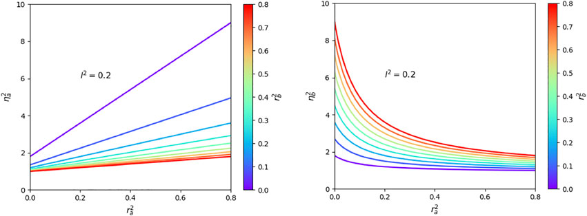
For symmetric mirrors, we have and . Substituting these constants into the above expressions, they simplify and we find that with
which can assume any value between 1 and 2. For example, for highly-reflecting symmetric mirrors with and we have (Furtak-Wells et al., 2018). However, for asymmetric mirrors, and are no longer bound from above. This is illustrated in Figure 2 which shows and for an asymmetric mirror with equal loss rates and . These rates are defined such that energy is conserved (Monzón and Sánchez-Soto, 1995; Barnett et al., 1998; Uppu et al., 2016) and
For example, suppose the reflection rate is relatively large, while is very small, as it applies when the mirror surface is very smooth and highly reflective on the right hand side but rough and highly dispersive on the left (cf. Figure 1). In this case, can be significantly larger than , if the loss rates and are similar in size (cf. Figure 2). This implies that the electric field observable in Eq. 19 is dominated by the contributions of the b rather than the a photons. This can be understood by taking into account that the b photons are present on both sides of the mirror interface in this case while, to a very good approximation, the a photons can only be seen on one side.
4.3 Discussion
In this subsection, we have a closer look at the spontaneous decay rates of an atom on the right hand side of a mirror-coated interface with coherent light absorption where x is positive. Using Eq. 35, in Eq. 34 simplifies to
with the mirror parameter given by
This equation shows that the difference between the spontaneous decay rates and depends on the phase which is the phase that complex electric field amplitudes accumulate upon reflection by the mirror surface on the same side as the atom. It also depends on the orientation of the atomic dipole moment with respect to the mirror surface, as one would intuitively expect.
However, a closer look at Eq. 39 also shows that the spontaneous decay rate depends in addition on all the reflection and transmission rates of the mirror interface. This might seem surprising but remember that the dipole interaction between the atom and the surrounding free radiation field plays an integral role in the spontaneous emission of a photon (cf. Eq. 25). In the experimental setup in Figure 1, the atom couples to incoming, reflected and transmitted photon modes which leads to interference effects and the strong dependence of on the atom-mirror distance x. Moreover, the strength of the atom-field interaction depends on the magnitude of the electric field observable at the position r of the atom (cf. Eq. 19). As we have seen in the discussion at the end of Section 3.1, normalising this observable is not straightforward, since the total energy of the a and the b photons is shared between the quantised EM field and the mirror interface (Furtak-Wells et al., 2018).
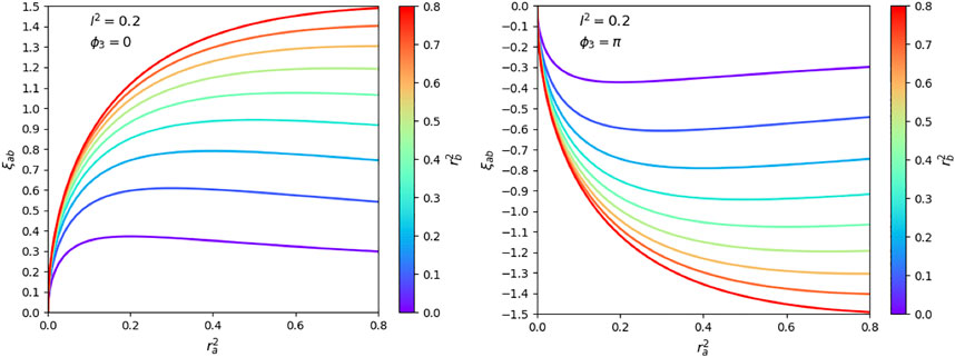
The reason for the dependence of on , , and is its dependence on the mirror constant . Figure 3 shows that can assume any value between and 1.5. For example, the case corresponds to a perfectly-reflecting mirror with , and or . From Figure 4 we see that can therefore assume any value between 0 and . The presence of loss in the mirror interface reduces the amount of light which can be transmitted and changes in a relatively complex way (cf. Eqs 36, 44). For example, increasing results in a reduction of , while increasing results in general in an increase of . To better illustrate the dependence of on mirror parameters, we will now have a closer look at concrete examples. First it will be shown that our approach reproduces well-known results for loss-less symmetric mirrors, thereby verifying the consistency of our approach. Afterward, we will discuss how the coherent absorption of light in the mirror surface alters atomic decay rates.
4.3.1 Dielectric Media Without Mirror Coatings
In the absence of any coating, energy is conserved and the overall transition matrix for incoming photons needs to be unitary. Taking this into account one can show that (Degiorgio, 1980; Zeilinger, 1981)
in this case. As a result, the mirror constant in Eq. 40 simplifies to
and depends only on r and . Figure 5A illustrates the dependence of on r and x for two different orientations of the atomic dipole moment and . Because of the dependence of the reflection rate r of a dielectric medium on its refractive index n (Novotny and Hecht, 2006),
the spontaneous decay rate depends on the optical properties of the media on both sides of the interface. This observation is in agreement with actual experiments (Drexhage, 1970; Chance et al., 1975a; Eschner et al., 2001; Creatore et al., 2009). It is also in agreement with the literature where the spontaneous decay of an atom in the presence of a dielectric medium has already been studied in great detail (Carniglia and Mandel, 1971; Wylie and Sipe, 1984; Khosravi and Loudon, 1991; Snoeks et al., 1995; Yeung and Gustafson, 1996; Urbach and Rikken, 1998; Xu et al., 2004; Wang et al., 2005; Creatore and Andreani, 2008; Eberlein and Zietal, 2012; Falinejad and Ardekani, 2019).
In the special case of a highly-reflecting mirror, which adds a minus sign to the electric field amplitude upon reflection (Morawitz, 1969; Stehle, 1970; Milonni and Knight, 1973; Arnoldus and George, 1988; Drabe et al., 1989; Meschede et al., 1990; Amos and Barnes, 1997; Matloob, 2000; Beige et al., 2002; Dorner and Zoller, 2002), we have , and . At , incoming and reflected light interferes destructively and the resulting y and the z components of the electric field vanish along the mirror surface. If there is no electric field to couple to, then there is no atom-field interaction and the atom cannot decay. In contrast to this, an atomic dipole which aligns parallel to the mirror surface couples only to the x component of the electric field. This component is now times its usual amplitude which results in an enhanced spontaneous decay rate of . A closer look at the case in Figure 5A shows that this is indeed the case.
4.3.2 Dielectric Media With Mirror Coatings
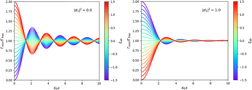
In the presence of mirror coatings, the possible absorption of light in the interface needs to be taken into account. As we have seen in Section 2, in the quantum mirror image detector method (Furtak-Wells et al., 2018), this is done by evolving photon states in exactly the same way as they would evolve in free space, i.e. without reducing their energy in time. However, as one can see from Eq. 19, photons which have either been transmitted or reflected by the mirror interface contribute less to the electric field observable at the location of the atom than photons which have not met the mirror. Intuitively, one might therefore expect that losses result in a significant reduction of the dependence of the spontaneous decay rate on the atom-mirror distance x. However, as Figure 5B shows, this is not the case. The calculations in Section 4.2 show that the presence of non-zero loss rates,
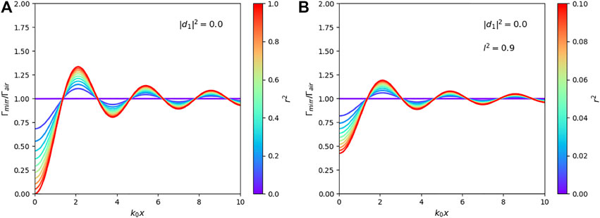
changes the normalisation constant of the electric field observable in Eq. 19. This means, losses not only affect the relative weighting of the terms in Eq. 19, they also affect the normalisation factor of the electric field observable. Hence the spontaneous decay rates with and without losses are more similar than one might naively expect. Figure 5B shows for a case with significant light absorption ( with ). Nevertheless, Figures 5A,B both show a strong change of with the atom-mirror distance x. The only difference is that, while varies between 0 and 2 in one case, it varies between 0.4 and 1.6 in the other.
Figure 6 shows cases, where the reflection rates are fixed and , while the loss rate l changes between 0 and its maximum possible value of r. As in Figure 5B, we observe a relatively weak dependence on the spontaneous decay rate on loss rates of the mirror interface. The most significant effect of the absorption of light in the mirror interface is seen for relatively small values of x which matches the results presented for example in Refs. (Yeung and Gustafson, 1996; Eberlein and Zietal, 2012).
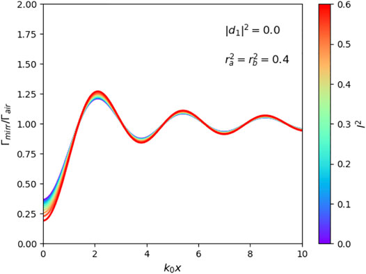
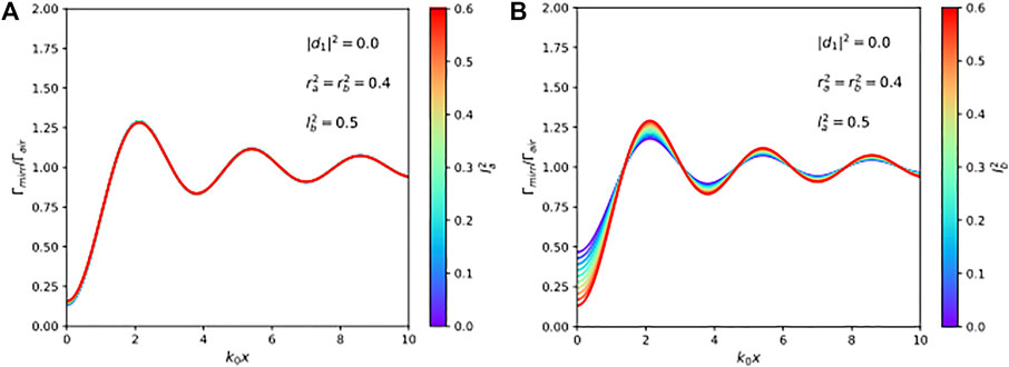
Finally, Figure 7 shows that the spontaneous decay rate depends differently on the loss rates and . For example, varying (which is the loss rate of light approaching the mirror from the same side as the atom) while keeping the same has almost no effect on the size of the spontaneous decay rate (cf. Figure 7A). This can be understood by noticing that light which has left the atom no longer affects its dynamics. Once a photon has been emitted, it does not matter whether it is absorbed in the mirror surface, by a far-away detector or by the walls of the laboratory. In contrast to this, changing (which is the loss rate of light approaching the mirror from the opposite side as the atom) can have a noticeable effect on the spontaneous decay rate (cf. Figure 7B). For example, increasing while keeping the same can result in an increase of the dependence of on the atom-mirror distance x. This occurs due to a reduction of the normalisation constant of the electric field observable in Eq. 19 which leads to an increase of the dipole interaction between the atom and the b photons.
5 Conclusion
The fluorescence properties of an atomic dipole depend on the so-called local density of states of the quantised EM field (van Tiggelen and Kogan, 1994; Sprik et al., 1996) which itself depends in a complex way on the properties of all of its surroundings. For example, as this paper illustrates, the spontaneous decay rate of an atom near a mirror-coated interface depends on the reflection and transmission rates, , , , and , of light approaching the mirror from both sides (cf. Figure 1). While standard methods, which are based on the calculation of Greens functions or on the introduction of triplet modes [cf. e.g. Refs (Khosravi and Loudon, 1991; Creatore and Andreani, 2008; Eberlein and Zietal, 2012)], already yield good agreement with experimental findings, this paper aims to provide more physical insight. The potential coherent absorption of light in the interface is explicitly taken into account by assuming that the mirror does not change the shape of incoming wave packets but only reduces amplitudes by given rates.
To obtain an expression for the electric field observable in the presence of a mirror-coated dielectric medium, this paper employs the quantum mirror image detector method (Furtak-Wells et al., 2018), doubles the standard Hilbert space of the EM field and maps the dynamics of incoming wave packets onto their dynamics in analogous free space scenarios. In this way, we are able to obtain an expression which is consistent with Maxwell’s equations but contains two unknown normalisation factors and (cf. Eq. 19). These constants cannot be derived by simply demanding that the energy observable of the EM field and the Hamiltonian of the experimental setup in Figure 1 are the same (Furtak-Wells et al., 2018). Instead we demand locality and assume that the spontaneous decay rate of an atom at a relatively large distance from the mirror interface coincides with its respective free space rates (cf. Eq. 18).
The main difference between the current paper and earlier work (Furtak-Wells et al., 2018) is that this paper considers a more general scenario. It is emphasised that the quantum optical properties of the atom depend on the characteristics of the media on both sides of the mirror interface. It is also shown that non-zero loss rates do not necessarily reduce the effect of the mirror by as much as one might naively expect. For example, the spontaneous decay rate of an atom can exhibit a relatively strong dependence on the atom-mirror distance x even for loss rates and as large as 0.9 (cf. Figure 5). In agreement with other authors (Chance et al., 1975b; Yeung and Gustafson, 1996; Eberlein and Zietal, 2012), we find that the effect of absorption in the medium is most felt by dipole moments close to the interface.
Data Availability Statement
The original contributions presented in the study are included in the article/Supplementary Material, further inquiries can be directed to the corresponding author.
Author Contributions
All authors contributed to the conception and design of this study. BD and AB wrote the first draft of the manuscript. BD, NF-W and AB performed and checked the analytical calculations. BD made all the figures in the manuscript with the help of NF. All authors contributed to manuscript revision and read and approved the submitted version.
Funding
We acknowledge financial support from the Oxford Quantum Technology Hub NQIT (Grant number EP/M013243/1).
Conflict of Interest
The authors declare that the research was conducted in the absence of any commercial or financial relationships that could be construed as a potential conflict of interest.
References
Amos, R. M., and Barnes, W. L. (1997). Modification of the Spontaneous Emission Rate ofEu3+ions Close to a Thin Metal Mirror. Phys. Rev. B 55, 7249–7254. doi:10.1103/physrevb.55.7249
CrossRef Full Text | Google Scholar
Arnoldus, H. F., and George, T. F. (1988). Spontaneous Decay and Atomic Fluorescence Near a Metal Surface or an Absorbing Dielectric. Phys. Rev. A. 37, 761–769. doi:10.1103/physreva.37.761
CrossRef Full Text | Google Scholar
Barnett, S. M., Jeffers, J., Gatti, A., and Loudon, R. (1998). Quantum Optics of Lossy Beam Splitters. Phys. Rev. A. 57, 2134–2145. doi:10.1103/physreva.57.2134
CrossRef Full Text | Google Scholar
Beige, A., Pachos, J., and Walther, H. (2002). Spontaneous Emission of an Atom in Front of a Mirror. Phys. Rev. A. 66, 063801. doi:10.1103/physreva.66.063801
CrossRef Full Text | Google Scholar
Bennett, R., Barlow, T. M., and Beige, A. (2016). A Physically-Motivated Quantisation of the Electromagnetic Field. Eur. J. Phys. 37, 14001. doi:10.1088/0143-0807/37/1/014001
CrossRef Full Text | Google Scholar
Bennett, R., and Buhmann, S. Y. (2020). Inverse Design of Light-Matter Interactions in Macroscopic QED. New J. Phys. 22, 093014. doi:10.1088/1367-2630/abac3a
CrossRef Full Text | Google Scholar
Carniglia, C. K., and Mandel, L. (1971). Quantization of Evanescent Electromagnetic Waves. Phys. Rev. D 3, 280–296. doi:10.1103/physrevd.3.280
CrossRef Full Text | Google Scholar
Chance, R. R., Miller, A. H., Prock, A., and Silbey, R. (1975). Fluorescence and Energy Transfer Near Interfaces: The Complete and Quantitative Description of the Eu+3/mirror Systems. J. Chem. Phys. 63, 1589–1595. doi:10.1063/1.431483
CrossRef Full Text | Google Scholar
Chance, R. R., Prock, A., Silbey, R., and Silbey, R. (1975). Comments on the Classical Theory of Energy Transfer. J. Chem. Phys. 62 (6), 2245–2253. doi:10.1063/1.430748
CrossRef Full Text | Google Scholar
Creatore, C., Andreani, L. C., Miritello, M., Lo Savio, R., and Priolo, F. (2009). Modification of Erbium Radiative Lifetime in Planar Silicon Slot Waveguides. Appl. Phys. Lett. 94, 103112. doi:10.1063/1.3098072
CrossRef Full Text | Google Scholar
Creatore, C., and Andreani, L. C. (2008). Quantum Theory of Spontaneous Emission in Multilayer Dielectric Structures. Phys. Rev. A. 78, 063825. doi:10.1103/physreva.78.063825
CrossRef Full Text | Google Scholar
Degiorgio, V. (1980). Phase Shift between the Transmitted and the Reflected Optical fields of a Semireflecting Lossless Mirror Is π/2. Am. J. Phys. 48, 81. doi:10.1119/1.12238
CrossRef Full Text | Google Scholar
Dorner, U., and Zoller, P. (2002). Laser-driven Atoms in Half-Cavities. Phys. Rev. A. 66, 023816. doi:10.1103/physreva.66.023816
CrossRef Full Text | Google Scholar
Drabe, K. E., Cnossen, G., and Wiersma, D. A. (1989). Localization of Spontaneous Emission in Front of a Mirror. Opt. Commun. 73, 91–95. doi:10.1016/0030-4018(89)90149-1
CrossRef Full Text | Google Scholar
Drexhage, K. H. (1970). Influence of a Dielectric Interface on Fluorescence Decay Time. J. Lumin. 1-2, 693–701. doi:10.1016/0022-2313(70)90082-7
CrossRef Full Text | Google Scholar
Eberlein, C., and Zietal, R. (2012). Quantum Electrodynamics Near a Huttner-Barnett Dielectric. Phys. Rev. A. 86, 022111. doi:10.1103/physreva.86.022111
CrossRef Full Text | Google Scholar
Falinejad, H., and Ardekani, S. N. (2019). Electromagnetic Field Quantization Near a Dielectric Slab and Spontaneous Emission Rate Determination. Appl. Phys. B 125, 208. doi:10.1007/s00340-019-7310-0
CrossRef Full Text | Google Scholar
Filonov, D., Kozlov, V., Shmidt, A., Steinberg, B. Z., and Ginzburg, P. (2018). Resonant Metasurface with Tunable Asymmetric Reflection. Appl. Phys. Lett. 113, 094103. doi:10.1063/1.5046948
CrossRef Full Text | Google Scholar
Furtak-Wells, N., Clark, L. A., Purdy, R., and Beige, A. (2018). Quantising the Electromagnetic Field Near Two-Sided Semi-transparent Mirrors. Phys. Rev. A. 97, 043827. doi:10.1103/physreva.97.043827
CrossRef Full Text | Google Scholar
Griffiths, D. J. (1962). in “ (Prentice-Hall).Introduction to Electrodynamics,”
Hodgson, D., Southall, J., Purdy, R., and Beige, A. (2021). Quantising the Electromagnetic Field in Position Space submitted; arXiv:2104.04499.
Kenanakis, G., Xomalis, A., Selimis, A., Vamvakaki, M., Farsari, M., Kafesaki, M., et al. (2015). Three-Dimensional Infrared Metamaterial with Asymmetric Transmission. ACS Photon. 2, 287–294. doi:10.1021/ph5003818
CrossRef Full Text | Google Scholar
Khosravi, H., and Loudon, R. (1991). Vacuum Field Fluctuations and Spontaneous Emission in the Vicinity of a Dielectric Surface. Proc. R. Soc. Lond. A 433, 1888. doi:10.1098/rspa.1991.0052
CrossRef Full Text | Google Scholar
Kwadrin, A., and Koenderink, A. F. (2013). Probing the Electrodynamic Local Density of States with Magnetoelectric point Scatterers. Phys. Rev. B 87, 125123. doi:10.1103/physrevb.87.125123
CrossRef Full Text | Google Scholar
Matloob, R. (2000). Radiative Properties of an Atom in the Vicinity of a Mirror. Phys. Rev. A. 62, 022113. doi:10.1103/physreva.62.022113
CrossRef Full Text | Google Scholar
Meschede, D., Jhe, W., and Hinds, E. A. (1990). Radiative Properties of Atoms Near a Conducting Plane: An Old Problem in a New Light. Phys. Rev. A. 41, 1587–1596. doi:10.1103/physreva.41.1587
PubMed Abstract | CrossRef Full Text | Google Scholar
Milonni, P. W., and Knight, P. L. (1973). Spontaneous Emission between Mirrors. Opt. Commun. 9, 119–122. doi:10.1016/0030-4018(73)90239-3
CrossRef Full Text | Google Scholar
Morawitz, H. (1969). Self-coupling of a Two-Level System by a Mirror. Phys. Rev. 187, 1792–1796. doi:10.1103/physrev.187.1792
CrossRef Full Text | Google Scholar
Novotny, L., and Hecht, B. (2006). Principles of Nano-Optics. Cambridge, United Kingdom: Cambridge University.
Plum, E., Fedotov, V. A., and Zheludev, N. I. (2009). Planar Metamaterial with Transmission and Reflection that Depend on the Direction of Incidence. Appl. Phys. Lett. 94, 131901. doi:10.1063/1.3109780
CrossRef Full Text | Google Scholar
Scheel, S., and Buhmann, S. Y. (2008). Macroscopic QED - Concepts and Applications. Acta Phys. Slovaca 58, 675. doi:10.2478/v10155-010-0092-x
CrossRef Full Text | Google Scholar
Scheel, S., Knöll, L., and Welsch, D.-G. (1999). Spontaneous Decay of an Excited Atom in an Absorbing Dielectric. Phys. Rev. A. 60, 4094–4104. doi:10.1103/physreva.60.4094
CrossRef Full Text | Google Scholar
Schwanecke, A. S., Fedotov, V. A., Khardikov, V. V., Prosvirnin, S. L., Chen, Y., and Zheludev, N. I. (2008). Nanostructured Metal Film with Asymmetric Optical Transmission. Nano Lett. 8, 2940–2943. doi:10.1021/nl801794d
PubMed Abstract | CrossRef Full Text | Google Scholar
Snoeks, E., Lagendijk, A., and Polman, A. (1995). Measuring and Modifying the Spontaneous Emission Rate of Erbium Near an Interface. Phys. Rev. Lett. 74, 2459–2462. doi:10.1103/physrevlett.74.2459
PubMed Abstract | CrossRef Full Text | Google Scholar
Southall, J., Hodgson, D., Purdy, R., and Beige, A. (2021). Locally Acting Mirror Hamiltonians. J. Mod. Opt. 68, 647–660. doi:10.1080/09500340.2021.1936241
CrossRef Full Text | Google Scholar
Sprik, R., Tiggelen, B. A. v., and Lagendijk, A. (1996). Optical Emission in Periodic Dielectrics. Europhys. Lett. 35, 265–270. doi:10.1209/epl/i1996-00564-y
CrossRef Full Text | Google Scholar
Stokes, A., Kurcz, A., Spiller, T. P., and Beige, A. (2012). Extending the Validity Range of Quantum Optical Master Equations. Phys. Rev. A. 85, 053805. doi:10.1103/physreva.85.053805
CrossRef Full Text | Google Scholar
Stourm, E., Lepers, M., Robert, J., Nic Chormaic, S., Molmer, K., and Brion, E. (2020). Spontaneous Emission and Energy Shifts of a Rydberg Rubidium Atom Close to an Optical Nanofiber. Phys. Rev. A. 101, 052508. doi:10.1103/physreva.101.052508
CrossRef Full Text | Google Scholar
Stratton, J. A. (1941). Electromagnetic Theory,. McGraw-Hill Book Company.
Tumkur, T. U., Kitur, J. K., Chu, B., Gu, L., Podolskiy, V. A., Narimanov, E. E., et al. (2012). Control of Reflectance and Transmittance in Scattering and Curvilinear Hyperbolic Metamaterials. Appl. Phys. Lett. 101, 091105. doi:10.1063/1.4746387
CrossRef Full Text | Google Scholar
Urbach, H. P., and Rikken, G. L. J. A. (1998). Spontaneous Emission from a Dielectric Slab. Phys. Rev. A. 57, 3913–3930. doi:10.1103/physreva.57.3913
CrossRef Full Text | Google Scholar
Wang, F.-H., Jin, Y.-P., Gu, B.-Y., Zhou, Y.-S., Wang, X.-H., and Du, M. L. (2005). Application of Closed-Orbit Theory to the Spontaneous Emission of Atoms Near a Single Dielectric Interface. Phys. Rev. A. 71, 044901. doi:10.1103/physreva.71.044901
CrossRef Full Text | Google Scholar
Wylie, J. M., and Sipe, J. E. (1984). Quantum Electrodynamics Near an Interface. Phys. Rev. A. 30, 1185–1193. doi:10.1103/physreva.30.1185
CrossRef Full Text | Google Scholar
Xu, Q., Almeida, V. R., Panepucci, R. R., and Lipson, M. (2004). Experimental Demonstration of Guiding and Confining Light in Nanometer-Size Low-Refractive-index Material. Opt. Lett. 29, 1626. doi:10.1364/ol.29.001626
PubMed Abstract | CrossRef Full Text | Google Scholar
Zeilinger, A. (1981). General Properties of Lossless Beam Splitters in Interferometry. Am. J. Phys. 49, 882–883. doi:10.1119/1.12387
CrossRef Full Text | Google Scholar
Zhukovsky, S. V., Novitsky, A. V., and Galynsky, V. M. (2009). Elliptical Dichroism: Operating Principle of Planar Chiral Metamaterials. Opt. Lett. 34, 1988. doi:10.1364/ol.34.001988
PubMed Abstract | CrossRef Full Text | Google Scholar
 Benjamin Dawson
 Nicholas Furtak-Wells2
 Thomas Mann
 Gin Jose
 Almut Beige