 Nathan Ortiz
 Sameer Rao
- Mechanical Engineering, The University of Utah, Salt Lake City, UT, United States
Sorbent coatings posses quick sorption kinetics due to their thin characteristic length scales for mass transfer and serve as an effective way to host sorbent material in a compact footprint. A tailorable coating technique is developed in this work to optimize the cycling ability of sorption based atmospheric water harvesters. Silane is used as a binding agent to adhere zeolite powder (AQSOA Z02) to thin aluminum sheets to provide a structurally sound and volumetrically dense method of packaging the sorbent while maintaining extremely fast sorption kinetics. A novel coating layering technique was used to manipulate the coating thickness slowing the adsorption times in exchange for better coating weight (). Through the multi coating technique we achieved a sorbent coating capable of collecting 1.167 and when projected onto a finned heat exchanger 458 . These are highly competitive numbers especially when considering the relatively low sorbent uptake of AQSOA Z02 (32% at RH>30% and T=25°C) when compared to modern sorbents such as Ni2Cl2(BTDD) that has uptake of 80% (RH>30% and T=25°C). We outline the coating, characterization and system projection calculations which can be extrapolated in the future to modern materials and alternative form factors.
1 Introduction
Atmospheric water harvesting (AWH) continues to attract attention as a potential solution for billions of people in need of safe drinking water around the globe (UNICEF, 2021; Ortiz and Rao, 2024a). Sorption-based AWH or SAWH utilizes naturally occurring and man-made sorbent materials with an affinity for water molecules. Novel sorbent materials such as zeolites and MOFs have been developed with large water uptake (Freni et al., 2015; Zheng et al., 2022; Rieth et al., 2019) and tailorable isotherms for performance in a wide range of operating conditions (i.e. relative humidity and temperature). In literature there is a lot of work focused on developing these materials Wang et al. (2023); Furukawa et al. (2014); Zheng et al. (2022), however, system level SAWH advancements have remained mostly stagnant (Ahrestani et al., 2023). Some groups have worked to package these novel materials in SAWH devices, where the packaging of the material appropriately requires consideration of heat and mass transfer in adsorbing systems. Some packaging techniques include packed bed systems (Shao et al., 2023), volumetric packaging of sorbent powders in porous media (Song et al., 2023; Ortiz and Rao, 2024b), and some works have investigated coatings (Lassitter et al., 2024; Freni et al., 2015; Jeremias et al., 2014). Coatings are able to provide very strong adsorption kinetics because of the short diffusion pathways of the thin substrate. The main consequence of using current coatings is their small coating weight () (Khwaldia, 2013), as thin coatings can not accommodate a large amount of sorbent material in a given coating area (Acoat). Sorbent kinetics and coating weight have inverse relationships with coating thickness which presents the question, what thickness will provide the best balance of performance to system size. To determine the existence of an optimal coating thickness for AWH system design which provides maximum volumetric productivity () we investigate the effects of coating thickness on AWH performance and project potential Pv for systems utilizing a coating matching the experimental coating sample characterization.
We introduce a silane-based sorbent coating, with the readily available zeolite AQSOA Z02, that has the ability to alter the coating thickness for kinetic performance and coating weight. The thickness of the coatings can be adjusted by repeatedly completing the coating process to adhere stacked layers on the same metal base layer. To determine the optimal thickness samples were fabricated with 1 (229.4μm), 2 (558.3μm) and 3 (837.1μm) coats and their sorption kinetics were experimentally determined. It was found that the thinnest samples (1 coat), when operated at 25°C and RH = 40%, had the highest daily productivity of 6.68 with the thickest samples (3 coats) resulting in the lowest theoretical system mass of 21.4 kg. The volumetric productivity () is a measure of the water production normalized by the volume of the adsorber and serves to demonstrate how compactly a system is able to achieve its water production Ortiz and Rao (2024b). We introduce a simple framework, that considers simple plate fin adsorber heat exchanger geometry, for demonstrating the relationship between sorbent kinetics, cycle uptake and overall daily performance to understand the consequences of coating thickness. When considering the volumetric productivity there existed a maximum at 2 coats of 458 . Other published SAWH devices have achieved a volumetric productivity up to 718 (Ortiz and Rao, 2024b) with the vast majority of the systems falling below 350 (Almassad et al., 2022; Hanikel et al., 2019; Xu et al., 2021; Wang et al., 2022; Shao et al., 2023; Chen et al., 2024). Multi-coating AWH demonstrates competitive Pv performance in the field and with further thickness and heat exchanger optimization could lead the field in compact AWH design. System level optimizations are essential for the continued progress of SAWH and this work serves to better answer how system geometries can impact realized system performance.
2 Methods
2.1 Coating preparation
Uniform aluminum samples (15mm x 22mm x 0.5mm) were fabricated using a laser cutting technique to ensure mass and size variability was minimal (+/−0.127mm+/− < 0.1mg), provided by OSH Cut (Spanish Fork, UT). It was essential to minimize mass variability as a blank sample served as a counterbalance in the dynamic vapor sorption (DVS) characterization. A DVS Adventure (Surface Measurement Systems) was used to accurately (0.1μg) capture the change in mass as a function of time while controlling the environmental conditions (RH = +/−0.1% and T = +/−0.02°C) for both cycling response curves and isotherm calculations.
Silane coatings are applied to the metal samples in a two step coating process, the first without added sorbent powder to serve as a foundation for better adherence and the second layer hosting the sorbent material. The first solution is prepared with 5% trimethoxy(propyl)silane, 5% deionized (DI) water and 90% 200-proof ethanol by weight. The constituents are mixed in a 5L beaker using an overhead electric stirrer (Lachoi). A dropper was used to carefully adjust the pH of the solution to 5 using acetic acid. The silane solution is sealed in a bottle and left to mix on a heating plate for 24 h at 80°C. Before the first coat is applied the aluminum sheets are cleaned and prepared using a NaOH solution (0.1 N NaOH) to remove any oxidation and grease from the bonding surface. Samples soaked in the alkaline solution for 60s and are then rinsed in DI water to remove the solution prior to the silane coating. This process follows the coating technique outlined in Freni et al. that was developed for SAPO-34 (Freni et al., 2015) which outlines the silane coating recipes and the process up until multiple coatings. This work substitutes the adsorbent of choice and builds on this technique to produce multiple sorbent coating layers. This process was selected due to the similar characteristics of SAPO-34 and AQSOA Z02, our sorbent of choice. Polyimide tape is used to mask the back surface of the aluminum sample preserving a bare surface for measurement purposes and the top of the sample to preserve a clean metal surface to serve as a thickness reference. The aluminum samples are partially immersed in the silane solution for 1 min and then immediately cured in a furnace at 80°C for 3 h. Sorbent powder, AQSOA Z02, is added to the silane mixture to prepare the second coating. AQSOA Z02 was added by 95 wt% of the remaining solution from the first coat. Using the overhead stirrer, sorbent powder must be added 100g at a time to allow for the slurry to homogenize. After the sorbent powder is completely incorporated into the solution, the entire batch undergoes 15 min of sonication followed by continuous stirring to prevent settling before the dipping procedure. After applying the sorption coating, the samples are cured in a furnace for 3 h at 80° C. After the samples have been cured, the masking tape is removed resulting in a partially coated sample. The coating process is outlined in the flowchart of Figure 1 with several of the steps being photographed in Figure 2.
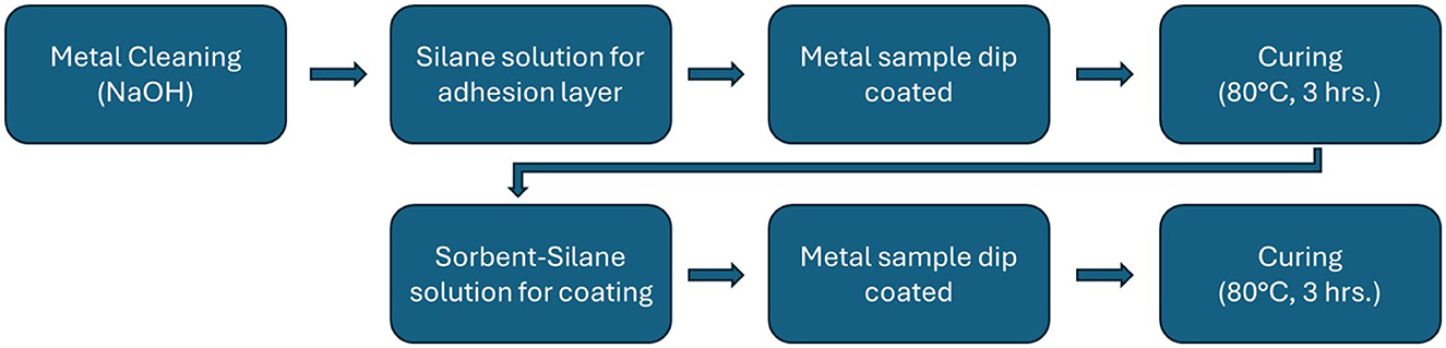
Figure 1. The coating process is summarized in the flowchart with the major steps highlighted as individual boxes. First the metal samples are cleaned, then the silane solution is prepared and the samples are dipped to coat them. A curing step ends this process until the next coat is to be applied. After the curing phase of the sorbent-silane coating the sample can either be finished or the steps in the bottom row can be repeated for multiple coatings.
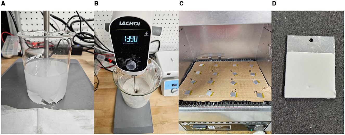
Figure 2. (A) Laser cut aluminum samples soak in a NaOH bath to remove oxides and remaining contaminants. (B) An overhead mixer was used to homogenize the added sorbent powder into a slurry for coating. (C) Samples were cured in a furnace set to 80°C for 3 h. The image shows the initial silane layer with no added sorbent but all curing sessions were identical. (D) A fully coated sample with the masking tape removed. The clean surface at the top of the sample is used to determine the height (i.e. thickness) of the coating.
Adjusting both dipping time and slurry composition did not result in adjusted coating thicknesses and therefore repeating the coating process was the only method we found to successfully adjust the final coating properties. To achieve a thicker coating cured samples were put through sequential dips being cured between each coat. Figure 3, shows a sample of each of the coating levels fabricated in our experiments. Three samples were fabricated for each level of coating, 1, 2 and 3 coats, to determine the average thickness and response from each level of coating.
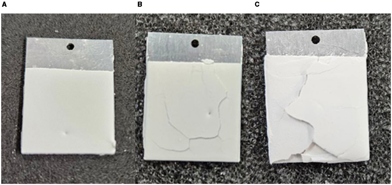
Figure 3. (A) Single coated sample which resulted in an average coating thickness of 229.4 μm. (B) A sample with two coats. Double coated samples averaged a thickness of 558.3 μm. (C) A sample with three coats. Triple coated samples averaged a thickness of 837.1 μm.
2.2 Thickness measurements
Thickness measurements were performed using a laser microscope (LEXT) to map the height of the coating in reference to the clean metal surface at several points along three lines on the left, right and center of the coating surface (Figure 4). Using the clean metal surface as a reference, the height of the coating can be determined to be the thickness that is averaged across all of the measurements for each sample. These points are manually selected to represent the bulk of the coating. Each sample scan can be found in supplementary information, including the individual thickness measurements and their locations. Table 1 shows the average coating thickness, coating mass and coating weight (g/m2). Coating variability was dependent on the number of coatings with the standard deviation of thickness being +/−16μm, +/−97.6μm and +/−56.3μm for 1, 2 and 3 coats respectively. The thickness and mass of each sample can be found in the supplementary data.
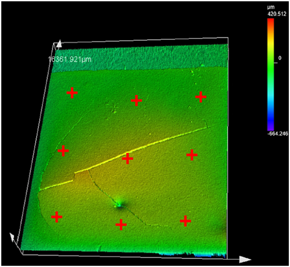
Figure 4. The red crosses represent the general location of the coating thickness measurements. The height at each mark was then averaged to create a single thickness for each sample.
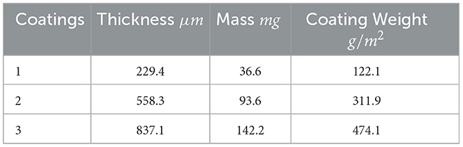
Table 1. Average thickness, mass, and area normalized mass data for the coating samples.
Adding each consecutive coating had diminishing thickness and mass additions to the sample with the first coat adding 229.4 μm and 36.6 mg, the second 328.9 μm and 57 mg and the third coat 278.8 μm and 48.6 mg. The second coat showed the largest increase in both thickness and in turn additional mass added. The coating weight represents the density with which the sorbent mass can be loaded into a system with higher coating efficiencies resulting in a smaller system footprint. The overall footprint directly impacts the volumetric productivity () which is determined by the amount of water able to be produced in a given volume of adsorber. To complete the analysis of the SAWH coatings, the sorption kinetics must be characterized to determine the time required for each adsorption cycle.
With the mass and volume of each coating sample characterized the porosity of the sample can be calculated (Equation 1).
The porosity, ε, is the void fraction of the coating and is calculated as the ratio of the coating density, ρcoat, to the crystal density of AQSOA Z02, ρcrystal, subtracted from unity. The crystal density of AQSOA Z02 is 1430kg(m3)−1 as reported by Lange et al. (2015). The average porosity for each of the coating layers was, 0.628, 0.609 and 0.604 for 1 coat, 2 coats and 3 coats respectively. A larger porosity fraction corresponds to more void space in the coating and faster sorption kinetics LaPotin et al. (2019). Comparing the various coating thicknesses the porosity is uniform with the increased porosity of the first coating likely a result of the increased silane which has a lower density than AQSOA Z02, 932kg(m3)−1. As more coating is added the percentage of silane drops and the true porosity settles to ≈60%.
3 Results
3.1 Sorption performance
Coatings with zeolite were analyzed using dynamic vapor sorption (DVS) mass analysis to determine the resulting isotherm and track the kinetic response to spontaneous humidity stimulus (40% RH and 25°C) (Figure 5). The isotherm of the silane-sorbent coatings was measured utilizing delaminated coating material to provide more accurate mass readings for the comparatively small mass of adsorbed water without the mass of the non participating substrate. Measuring the isotherm of the coating sample demonstrates that no significant deterioration was observed from the coating process. Using known uptake (kgwater/kgsorbent) of the pure sorbent material and the estimated mass concentration (kgsorbent/kgcoat) from the coating preparation the expected mass of adsorbed water can be validated (Figure 5A). The isotherm of the coating material shows a slight decrease in uptake in comparison to the raw powder (≈3% RH>30%) due to the added silane mass in the coating. The extra mass does not participate as a sorbent but is counted toward the sorbent composite mass in uptake calculations. After the curing process the ethanol and water are evaporated leaving sorbent powder and the silane binder which now makes up less than 5% of the coating.
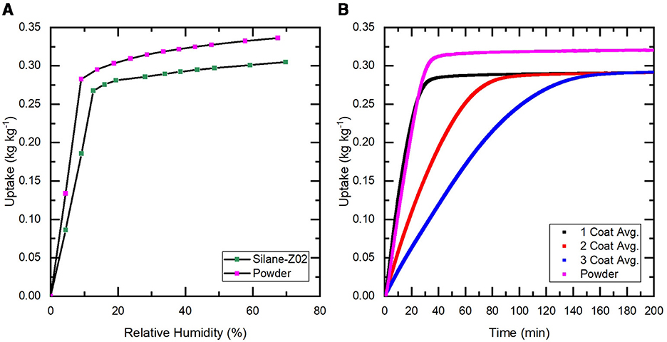
Figure 5. (A) Isotherms at 25°C for both a sample of the sorbent coating removed from a cured sample and unprocessed zeolite powder to serve as a control. (B) The average change in mass of adsorbed water as a function of time when exposed to a sudden 40% RH stream is shown for the group of samples at each coating level (i.e. 1, 2, 3). The response of unprocessed zeolite powder is also shown to demonstrate the baseline performance. The raw powder response is shown in violet, it reaches the full uptake potential of AQSOA Z02 (0.32 kgwater/kgsorbent) where the coating samples only achieve (0.27 kgwater/kgsorbent).
Sorption kinetics are compared at 40% RH and 25°C which represents arid conditions that are typically targeted with SAWH systems. Each sample is first completely regenerated at 125°C and 0% RH then left to cool to 25°C while maintaining a completely dry air stream. When the temperature and mass are stable, the incoming air stream is injected with water vapor up to 40% RH and the change in mass is recorded as a function of time. The sorbent will collect water until it reaches its equilibrium but will slow down drastically as it approaches its equilibrium state due to the vapor concentration difference decreasing between the ambient and inside the sorbent crystal structure (Bezrukov et al., 2023) (Figure 6). Truncating the slow kinetics will allow for significantly more daily cycles which can result in more daily water capture at the cost of increased energy usage, see Table 2. Truncation can be defined as a percentage of the equilibrium uptake value that the sorbent is allowed to capture before desorption.
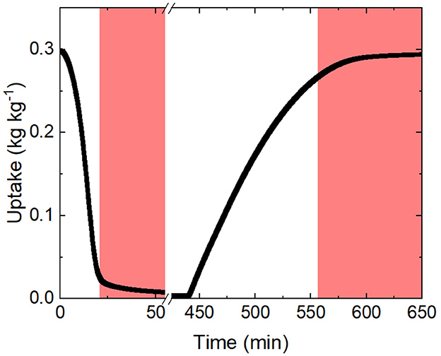
Figure 6. The curve above is an example of the change in mass as a function of time given a desorption condition followed by an adsorption condition demonstrating a cycle with no truncation. The regions shaded red highlight the end of both the desorption and adsorption phase where the change in mass is the slowest due to the proximity to its equilibrium state. Ending each cycle in this region can potentially increase daily production.
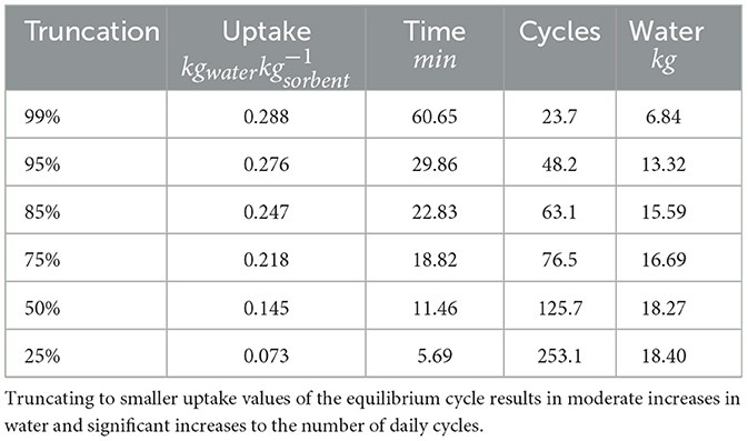
Table 2. Truncation study for a single coating sample based on the equilibrium time response measured using the DVS.
The thermal efficiency (ηth, vapor) of the AHX was estimated as
where mwater, desorbed, kg is the total mass of water vapor that is desorbed, is the enthalpy of evaporation of water, and Qin, kJ is the total thermal energy input for desorption provided by the heater (Kim et al., 2017). The energy input to the system can be understood in three categories, the enthalpy of adsorption hadsortion, sensible heating Qsens and thermal losses Qloss. Sensible heating represents the largest thermal inefficiency in an SAWH process where the sorption material and the structure that hosts it must be cycled from ambient temperature to the desorption temperature (125°C) to release the water. Energy spent on sensible heating does not directly overcome the heat of adsorption, the energetic cost of releasing the captured water vapor. When analyzing the truncation study performed for a single coating sample it can be observed that the total daily water that could be captured assuming 1 kg of sorbent powder increases steadily as more of the cycle is removed. However, this increase in water is overshadowed by the number of cycles which increases by more than 500% while the increase in water is only 38.4%.
To operate the system efficiently from a thermal efficiency perspective, in this study the uptake cycle was truncated at 95% of its full uptake resulting in adsorption times of, 29.86 min, 76.26 min and 131.43 min from 1 to 3 coats. Desorption at 125°C is less susceptible to mass transfer resistances incurred by coating thickness as the driving force is significantly large but a slowing effect is still present, therefore the desorption was truncated to 1% uptake. The desorption times for the various coating layers are 29.7 min, 30.29 min and 39.32 min from 1 to 3 coats resulting in total cycle times of 59.56 min, 106.55 min and 170.75 min.
Based on the average cycle times and water vapor collection per cycle the daily water productivity () and water footprint () can be determined. The total cycle time tcycle, is the summation of the desorption and adsorption phases (Equation 3. Daily cycles can be determined by dividing a single day (1440 min/day) by the total cycle time with partial cycles being important as over an extended operational period partial cycles will improve water capture. The total water capture can be determined by the number of daily cycles (Ncycles) times the water captured per cycle or the difference in uptake from adsorption to desorption (ωcycle), Equation 4.
The productivity from thin to thickest coating is: 6.68, 3.74 and 2.35 . Thinner coats are able to cycle many more times per day, 24.2 compared to 8.4, and therefore the same sorbent powder is capturing more water compared to a system that is slower but contains higher sorbent mass.
The relationship between water footprint and coating thickness is less straightforward. Thinner coatings can produce more water by mass but with relatively small amounts of sorbent the total water capture will be lower. The water footprint can be calculated by the daily productivity times the coating weight as shown in Equation 5.
A single coat can produce 0.815 , 2 coats will produce 1.167 and 3 coats will produce 1.115 . The maximum water footprint is achieved by the samples with 2 coats as they serve as the perfect balance of coating weight and cycle time which have an inverse relationship.
3.2 Stability and cycling
To demonstrate the cycling stability of the coating for mechanical, sorption uptake and kinetic uniformity a coating sample underwent consecutive controlled cycles in the DVS. To mimic the expected behavior of a rapid cycling AWH device a program was developed which first completely regenerates the sorbent in the coating by exposing it to a 125°C 0% RH airstream until it has reached it has reached its minimum mass, or dry mass. The regeneration step is terminated when the change in mass is less than 0.002 %/min. The subsequent cycle step is the cooling phase where the airstream returns to 25°C but maintains 0% RH to prevent premature adsorption. The cooling phase lasts 180 min to give the thin sample sufficient time to acclimate to ambient temperature. Finally, the sample is exposed to the adsorption conditions of 25°C and 40% RH and left to adsorb until it reaches its equilibrium (i.e. (%/min). The cycle is repeated 5 times to determine the presence of any variability in performance. The resulting plot shows the continuous uptake of the coating sample as it undergoes its 5 cycles (Figure 7).
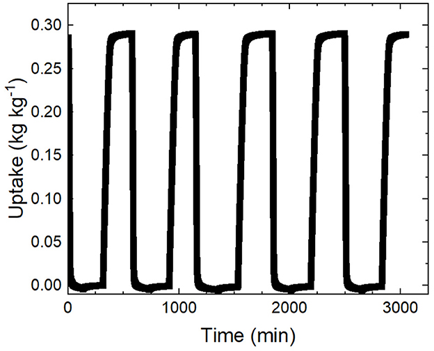
Figure 7. The continuous sorption uptake is shown for the duration of the 5 cycle experiment. The sorption uptake for each cycle plateaus at 0.29 +/- 0.00 demonstrating consistent sorption performances and requires 392.0 +/- 23.6 min to reach 95% uptake each cycle signifying consistent kinetic performance.
The cycling experiments demonstrate strong sorption uptake and kinetic consistency across cycles which can be quantified by the standard deviation of equilibrium uptake and cycle time. The cycles had an equilibrium uptake of 0.29 +/- 0.00 . The sorption kinetics can be compared by looking at the time required to desorb, cool and then adsorb until it reaches 95% of its equilibrium uptake. It is more consistent to compare the adsorption kinetics up to 95% of its equilibrium due to the tendency of the samples to drift at the equilibrium point in the DVS (+/- 0.01 mg) extending the automatic termination point for each cycle. The time required for the cycles averaged 391.97 +/- 23.63 min for which the 6% variation can be explained by the internal RH and temperature variance of the DVS control.
3.3 Projection framework
To better understand the consequences of tailoring coating thickness a projection exercise can be performed based on the sorption kinetics and uptake values that have been determined. A full scale SAWH system should be sufficiently large to produce enough water for a small family; 15 L/day is enough drinking water for 3–5 persons (TBMed-577, 2005). Using the daily productivity () of the coated samples the total amount of sorbent coating required to produce 15L/day can be calculated, Equation 6.
The coating weight can translate the total coating mass into a required coating area resulting in a known system mass and area. To design practical applications for SAWH the adsorbent coating can be assumed to take the form of an aluminum finned heat exchanger with each fin being a 25cm×25cm square of thickness 1 mm (tfin) and fin pitch of 3 mm (tpitch) to allow for adequate air flow. This coated heat exchanger will be referred to as the adsorbent heat exchanger (AHX) moving forward. Since both sides of each fin can be coated the total area required for coating can be achieved by half the area of aluminum (Equation 7).
Here the mass of coating required mcoat is determined from the desired daily output and the daily productivity P.
To determine the projected AHX volume the number of fins was determined, rounding up to the nearest whole fin (Equation 8).
The number of fins Nfins is determined geometrically given the area of coating required Acoat and the area of each fin Afin.
Using the thickness of the fins and the prescribed fin pitch the height of the AHX (HAHX) can be calculated with the following formulation (Equation 9), and the volume determined by the product of the fin footprint () and the determined height, Equation 10.
The number of required fins previously determined and the desired fin spacing, tpitch can be used to determine the total height of the AHX fin stack.
When the height of the AHX has been determined, HAHX, the assumed area of each fin, Afin, by the height will result in the total AHX volume for the specified design parameters. The resulting system characteristics are highlighted in Figure 8 with more calculation details available in supplementary information.
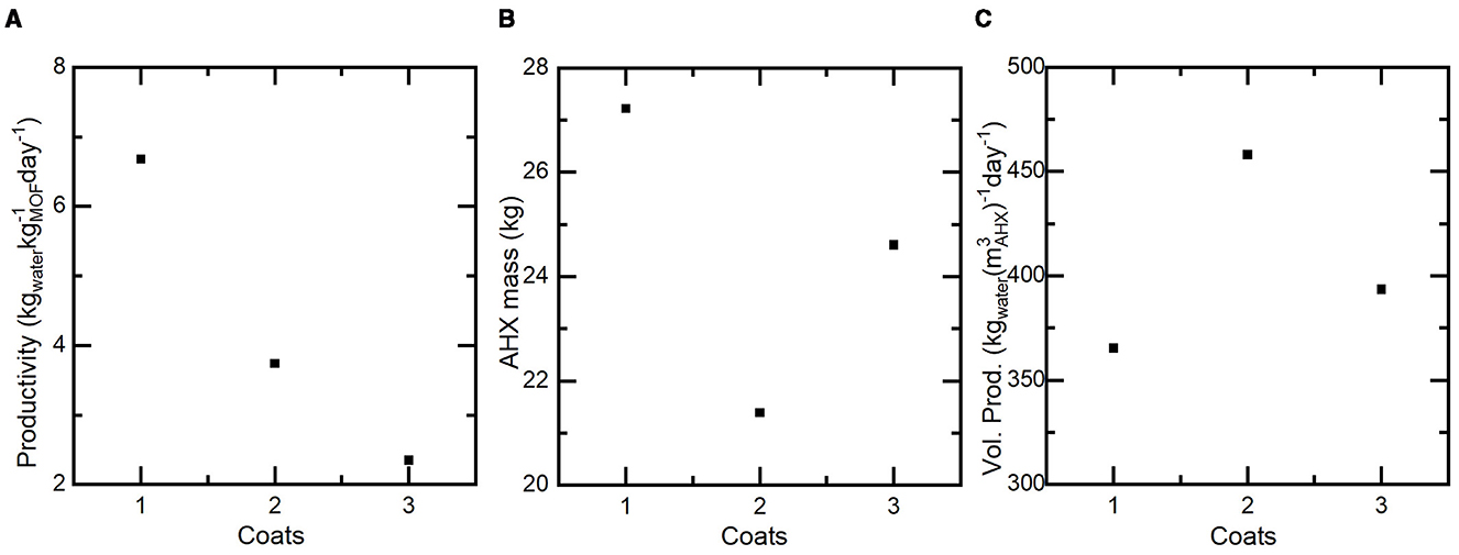
Figure 8. (A) The daily productivity of a projected system utilizing 1, 2 or 3 coats in a heat exchanger based SAWH device. Thicker coatings lead to lower daily productivity due to the increased sorbent mass of the system and decreased daily cycles. (B) The AHX mass includes the coating and aluminum fins as a function of coating thickness. There is a minimum mass at 2 coats where the system can produce the required 15L/day with the least number of coated fins. (C) The volumetric productivity of each system as a function of coating thickness. Similar to the AHX mass minimizing required fins minimized the overall system volume for a maximum performance at 2 coats.
As seen in the coated samples, productivity decreases significantly as more coatings are added. This is a function of slow kinetics limiting the ability of the coating to capture its full potential several times per day and in turn requiring more sorbent mass to achieve the daily goal of 15L of water. The inverse relationship of coating weight (Wcoat) and cycle time provides an opportunity for thickness optimization to achieve the maximum amount of water with the least system bulk (i.e. mass and volume). To calculate the mass of each projected AHX, mAHX (Equation 11) was used where the density of aluminum is .
The total mass of aluminum in the AHX is determined as the product of the specified volume of each aluminum fin, Vfin, the number of required fins, Nfin, and the density of aluminum. When the required mass of coating is added to the aluminum mass the mass of the AHX is defined, mAHX. The AHX mass has a minimum at 2 coats of 21.4kg with 17.4kg being the aluminum fins and the remaining 4kg being the sorbent coating and only making up 18.7% of the total mass. The significant aluminum mass comes from the required 103 total fins to achieve the required area for 4kg of sorbent coating. For the 3 coat sample that has the highest coating weight the AHX mass was 24.6kg, requiring 108 fins and the coating accounting for 6.4kg or 26% of the total AHX mass which was the maximum. With 1 coat the system required the highest number of fins, 148 and had the highest mass of 27.2kg with the coating representing 8.2% of the mass.
To calculate the volumetric productivity (Pvol) the following equation is used (Equation 12), where mwater is the mass of the produced water and VAHX is the total AHX volume of each system.
A similar relationship can be seen when the volumetric productivity (Pvol) is assessed for each system. The highest volumetric productivity of 458 is achieved by the system with 2 sorbent coats since that system utilizes the least number of fins and therefore has the smallest AHX volume (0.033 m3).
4 Conclusion
A silane-based coating process was developed to compactly package sorbent powder into a usable form factor, which was demonstrated with the zeolite AQSOA Z02. In the future the sorbent of choice could be swapped for higher performing materials that also benefit from thin coatings. This work has demonstrated a technique that allows for thickness of the coating to be controlled such that, during the design phase of an SAWH device, the sorbent performance can be tailored to the application. It is important to note the increased susceptibility of delamination with increased coatings that can be seen in the triple coated samples (Figure 3). To prevent this, it is best to avoid going beyond two coatings. Future development of this technique should focus on the structural strength of repeated coatings, solution additives or interfacial silane layers may result in improved performance. An optimal thickness was shown to exist at 2 coatings, taking advantage of a balance of fast sorption kinetics and coating weight, improving the volumetric productivity from 365 to 458 . This relationship between the sorption kinetics and the characteristic length scale for mass transfer can be found in all iterations of SAWH devices and a similar projection method is applicable to all cycling SAWH systems. The ability to change and optimize system level performance at the sorbent packaging level is a crucial variable in the development of AWH that has not been explored fully. Considering other system level parameters such as size and weight benefit the most from these optimization studies, when compared to daily productivity (), this process focuses on practicality challenges that still plague the AWH field. With this work we have provided the blueprint for a highly competitive SAWH form factor that could be improved readily by incorporating higher performance sorbent materials. This benefit is synergistic, since a well optimized packaging and cycling methodology are required to reap the full potential of high performance sorbents. We hope that outlining the process from sorbent characterization to projections of system performance can inform future SAWH prototypes to boost productivity, volumetric productivity or minimize system mass.
Data availability statement
The original contributions presented in the study are included in the article/Supplementary material, further inquiries can be directed to the corresponding author.
Author contributions
NO: Formal analysis, Visualization, Data curation, Methodology, Validation, Investigation, Writing – review & editing, Conceptualization, Writing – original draft. SR: Methodology, Visualization, Conceptualization, Supervision, Investigation, Funding acquisition, Writing – review & editing.
Funding
The author(s) declare that financial support was received for the research and/or publication of this article. The authors acknowledge funding from the National Science Foundation Graduate Research Fellowship Program. Funding agencies: DEVCOM grant no. W911QY-19-1-0010, NSF GRFP grant no. 2139322.
Acknowledgments
The authors would like to thank J. Magnone, S. Mcgraw-Manza, G. Flock, P. Lavigne, and the DEVCOM Soldier Center for their guidance and support of our work. OPSEC public release approval no. PR2025-2273.
Conflict of interest
NO and SR declare that they are founders of Sorption Water Solutions LLC, a company working in the commercial atmospheric water harvesting industry.
Generative AI statement
The author(s) declare that no Gen AI was used in the creation of this manuscript.
Publisher's note
All claims expressed in this article are solely those of the authors and do not necessarily represent those of their affiliated organizations, or those of the publisher, the editors and the reviewers. Any product that may be evaluated in this article, or claim that may be made by its manufacturer, is not guaranteed or endorsed by the publisher.
Supplementary material
The Supplementary Material for this article can be found online at: https://www.frontiersin.org/articles/10.3389/frwa.2025.1606252/full#supplementary-material
References
Ahrestani, Z., Sadeghzadeh, S., and Emrooz, H. B. M. (2023). An overview of atmospheric water harvesting methods, the inevitable path of the future in water supply. RSC Adv. 13:10273–10307. doi: 10.1039/D2RA07733G
Almassad, H. A., Abaza, R. I., Siwwan, L., Al-Maythalony, B., and Cordova, K. E. (2022). Environmentally adaptive MOF-based device enables continuous self-optimizing atmospheric water harvesting. Nat. Commun. 13:4873. doi: 10.1038/s41467-022-32642-0
Bezrukov, A. A., O'Hearn, D. J., Gascón-Pérez, V., Darwish, S., Kumar, A., Sanda, S., et al. (2023). Metal-organic frameworks as regeneration optimized sorbents for atmospheric water harvesting. Cell Reports Phys. Sci. 4:101252. doi: 10.1016/j.xcrp.2023.101252
Chen, Z., Yang, X., Cui, Z., Du, S., and Wang, R. (2024). Continuous atmospheric water production coupled with humidity regulation enabled by a MOF-based humidity pump. Nano Energy 125:109596. doi: 10.1016/j.nanoen.2024.109596
Freni, B., Frazzica, C., and Sapienza, C (2015). Sapo-34 coated adsorbent heat exchanger for adsorption chillers. Appl. Therm. Eng. 82, 1–7. doi: 10.1016/j.applthermaleng.2015.02.052
Furukawa, H., Gandara, F., Zhang, Y.-B., Jiang, J., Queen, W. L., Hudson, M. R., et al. (2014). Water adsorption in porous metal–organic frameworks and related materials. J. Am. Chem. Soc. 136, 4369–4381. doi: 10.1021/ja500330a
Hanikel, N., Prévot, M. S., Fathieh, F., Kapustin, E. A., Lyu, H., Wang, H., et al. (2019). Rapid cycling and exceptional yield in a metal-organic framework water harvester. ACS Cent. Sci. 5, 1699–1706. doi: 10.1021/acscentsci.9b00745
Jeremias, F., Fröhlich, D., Janiak, C., and Henninger, S. K. (2014). Advancement of sorption-based heat transformation by a metal coating of highly-stable, hydrophilic aluminium fumarate MOF. RSC Adv. 4, 24073–24082. doi: 10.1039/C4RA03794D
Khwaldia, K. (2013). Physical and mechanical properties of hydroxypropyl methylcellulose–coated paper as affected by coating weight and coating composition. BioResources 8, 3438–3452. doi: 10.15376/biores.8.3.3438-3452
Kim, H., Yang, S., Rao, S. R., Narayanan, S., Kapustin, E. A., Furukawa, H., et al. (2017). Water harvesting from air with metal-organic frameworks powered by natural sunlight. Science 356, 430–434. doi: 10.1126/science.aam8743
Lange, M. F., Verouden, K. J. F. M., Vlugt, T. J. H., Gascon, J., and Kapteijn, F. (2015). Adsorption-driven heat pumps: the potential of metal–organic frameworks. Chem. Rev. 115, 12205–12250. doi: 10.1021/acs.chemrev.5b00059
LaPotin, A., Kim, H., Rao, S. R., and Wang, E. N. (2019). Adsorption-based atmospheric water harvesting: Impact of material and component properties on system-level performance. Acc. Chem. Res. 52, 1588–1597. doi: 10.1021/acs.accounts.9b00062
Lassitter, T., Hanikel, N., Coyle, D. J., Hossain, M. I., Lipinski, B., O'Brien, M., et al. (2024). Mass transfer in atmospheric water harvesting systems. Chem. Eng. Sci. 285:119430. doi: 10.1016/j.ces.2023.119430
Ortiz, N., and Rao, S. (2024a). “Review of rain and atmospheric water harvesting history and technology,” in Oxford Research Encyclopedia of Environmental Science (Oxford).
Ortiz, N. P., and Rao, S. R (2024b). Compact rapid cycling fuel-fired atmospheric water harvesting device for all-day water production. Cell Reports Phys. Sci. 5:102115. doi: 10.1016/j.xcrp.2024.102115
Rieth, A. J., Wright, A. M., Skorupskii, G., Mancuso, J. L., Hendon, C. H., and Dinca, M. (2019). Record-setting sorbents for reversible water uptake by systematic anion exchanges in metal–organic frameworks. J. Am. Chem. Soc., 141, 13858–13866. doi: 10.1021/jacs.9b06246
Shao, Z., Wang, Z.-S., Lv, H., Tang, Y.-C., Wang, H., Du, S., et al. (2023). Modular all-day continuous thermal-driven atmospheric water harvester with rotating adsorption strategy. Appl. Phys. Rev. 10:041409. doi: 10.1063/5.0164055
Song, W., Zheng, Z., Alawadhi, A. H., and Yaghi, O. M. (2023). MOF water harvester produces water from Death Valley desert air in ambient sunlight. Nature Water 1, 626–634. doi: 10.1038/s44221-023-00103-7
TBMed-577 (2005). Sanitary Control and Surveillance of Field Water Supplies Directive 5000.1. Technical Report. Headquarters Department of the ARMY.
Wang, J., Ying, W., Hua, L., Zhang, H., and Wang, R. (2023). Global water yield strategy for metal-organic-framework-assisted atmospheric water harvesting. Cell Reports Physical Science, 4:101742. doi: 10.1016/j.xcrp.2023.101742
Wang, W., Pan, Q., Xing, Z., Liu, X., Dai, Y., Wang, R., et al. (2022). Viability of a practical multicyclic sorption-based water harvester with improved water yield. Water Res. 211:118029. doi: 10.1016/j.watres.2021.118029
Xu, J., Li, T., Yan, T., Wu, S., Wu, M., Chao, J., et al. (2021). Ultrahigh solar-driven atmospheric water production enabled by scalable rapid-cycling water harvester with vertically aligned nanocomposite sorbent. Energy & Environm. Sci. 14, 5979–5994. doi: 10.1039/D1EE01723C
Keywords: water harvesting, coating, zeolite, sorbent, system design
Citation: Ortiz N and Rao S (2025) Tailored silane based sorbent coatings for compact atmospheric water harvesting devices. Front. Water 7:1606252. doi: 10.3389/frwa.2025.1606252
Received: 04 April 2025; Accepted: 04 June 2025;
Published: 23 June 2025.
Edited by:
Amin Mojiri, Arizona State University, United StatesReviewed by:
Xiangyu Li, The University of Tennessee, Knoxville, United StatesHan Fu, Arizona State University, United States
Copyright © 2025 Ortiz and Rao. This is an open-access article distributed under the terms of the Creative Commons Attribution License (CC BY). The use, distribution or reproduction in other forums is permitted, provided the original author(s) and the copyright owner(s) are credited and that the original publication in this journal is cited, in accordance with accepted academic practice. No use, distribution or reproduction is permitted which does not comply with these terms.
*Correspondence: Sameer Rao, cy5yYW9AdXRhaC5lZHU=