 Siyu Zhong
 Ilyes Ait Aissa
 Gen Huang
 Peter Holtappels
 Roland Dittmeyer
- Institute for Micro Process Engineering (IMVT), Karlsruhe Institute of Technology (KIT), Karlsruhe, Germany
Electrochemical CO2 reduction represents a promising approach for mitigating carbon emissions while generating value-added fuels and chemicals. While catalyst design mainly dictates activity and product selectivity, system-level performance is strongly influenced by the interplay between electrolyzer configuration and operating parameters. In this study, a zero-gap membrane electrode assembly electrolyzer incorporating a cation exchange membrane is systematically investigated under practical considerations. The applicable operating window is successfully extended to elevated temperatures and pressures, demonstrating robust practicality and efficient conversion. Comprehensive evaluation of cell voltage, Faradaic efficiency, and energy efficiency reveals that a balanced combination of catalyst loading, electrolyte concentration, and flow rate enables high CO selectivity (>90%) and energy efficiency exceeding 40% at moderate current density (100 mA/cm2). By integrating multiple operational parameters, this work advances the application of cation exchange membrane based CO2 electrolysis and offers practical insights for bridging laboratory research and scalable implementation.
Introduction
The electrochemical reduction of carbon dioxide (CO2RR) represents a promising strategy to convert CO2 into value-added fuels and chemicals, addressing both environmental challenges and energy sustainability (Lu et al., 2024; She et al., 2024). The development of CO2 electrolysis is navigated by challenging techno-economic performance metrics (Segets et al., 2023). Sargent et al. emphasize that achieving cell voltages below 3.0 V (ideally <2.0 V), current densities above 0.2 A/cm2, Faradaic efficiencies (FE) higher than 80%, and energy efficiencies (EE) greater than 50%, alongside long-term operational stability comparable to water electrolysis, are critical for CO2RR industrial adoption (Kibria et al., 2019). In addition, considering the potential exposure to elevated temperatures in practical operating environments (Li et al., 2025; Pelzer et al., 2025) and the close integration with upstream direct air capture (DAC) or downstream gas separation units (Siegmund et al., 2021; Lee et al., 2024), the electrolysis system should be capable of tolerating fluctuations in both pressure and temperature.
Among the diverse electrolyzer configurations, membrane electrode assembly (MEA) systems are increasingly favored for their ability to sustain high current densities, minimize ohmic resistance, and support compact, scalable reactor designs, rendering them particularly attractive for industrial deployment (Rabiee et al., 2021; Ge et al., 2022). Although many studies have been conducted in H-type or liquid-feed flow cells (Hursan and Janaky, 2023; Wang et al., 2023; Ko et al., 2024), the optimization strategies and performance conclusions drawn from them may not be directly applicable to zero-gap electrolyzer systems due to differences in gas phase transport, membrane hydration kinetics, and electrode interface behavior (Kas et al., 2021; Brückner et al., 2024; Ehlinger et al., 2024; Park et al., 2024). Growing attention has been directed toward MEA-based systems, yet the influence of multiple operating parameters in CO2RR remains insufficiently understood and offers substantial scope for further investigation.
In this study, a zero-gap electrolyzer equipped a cation-exchange membrane (CEM) drives CO2 reduction at the cathode (CO2 + 2H+ + 2e− → CO + H2O) and oxygen evolution at the anode (2H2O → O2 + 4H+ + 4e−). Carbon monoxide is pursued as the primary product because it is a versatile C1 platform molecule, serving as both a chemical feedstock and a key component of syngas, and can be upgraded to long-chain hydrocarbons through Fischer–Tropsch synthesis (Nguyen et al., 2019). Its versatility and integration with existing infrastructure establish CO as a practical and industrially significant target for CO2 electrolysis (Lee et al., 2024). The cathode was based on identical Ag nanoparticles, thereby excluding variations in the intrinsic kinetic properties of the electrocatalyst. Furthermore, the impact of multiple extrinsic operational variables is examined. Catalyst layer thickness is adjusted to balance performance with material efficiency, CO2 flow rate is varied to optimize reactant utilization, and anolyte concentration is tuned to probe reaction kinetics. Temperature and pressure are further modulated to explore compatibility with downstream thermal or catalytic upgrading. To control intervariable effects and ensure unbiased comparison, this study operates all experiments at a constant current density of 100 mA/cm2, selected as a stable electrochemical reference for variations in operating parameters as well as a conservatively practical benchmark (Mot et al., 2020; Reyes et al., 2020). Specifically, the system sustains high performance with >90% FE and >30% EE of CO product across a broad range of operating conditions, demonstrating structural stability, functional flexibility, and process adaptability. These findings provide actionable guidelines for system-level design and operational control in scalable CO2 electrolysis.
Methods
Preparation of MEA
Silver nanopowder (APS 20–40 nm, 99.9%, Thermo Scientific Chemicals) was employed as the cathodic catalyst, while iridium oxide nanopowder (Fuel Cell Store) served as the anodic catalyst. For the gas diffusion media, Sigracet 39 BB carbon paper and platinum-coated titanium fiber felt (Fuel Cell Store) were used as the cathode gas diffusion layers (GDL) and anode GDL, respectively. For consistency, the active area for GDL was standardized to 12 cm2. To prepare the cathode catalyst ink, 30 mg of silver nanopowder was dispersed in 2 mL of isopropanol along with 40 µL of 5 wt% Nafion solution. The mixture was ultrasonicated for 20 min to ensure homogeneity. The resulting ink was then manually sprayed onto the microporous layer (MPL) side of the cathode GDL, forming the cathode catalyst layer (cCL) with a target loading of approximately 1.5 mg/cm2. Then spraying process was repeated two or three times sequentially to obtain 2- and 3-layer silver electrodes. Twenty independently prepared electrodes were produced for each nominal thickness (1-, 2-, and 3-layer cCLs) under identical spraying conditions. Gravimetric analysis showed silver loadings with relative standard deviations below 5% across batches, and representative electrodes were selected for subsequent testing. The anode catalyst layer was prepared similarly by spraying IrO2 nanopowder uniformly onto the GDL for a homogeneous coating. The Nafion 212 membrane was thoroughly hydrated in deionized water and then placed between the cathode and anode to complete the MEA arrangement, which is compressed by approximately 27% of its thickness in the customized zero-gap electrolyzer. Scanning electron microscope (SEM) photos of the electrodes were obtained through a JEOL JXA 8530F microscope.
Electrocatalytic testing
A custom modified electrolyzer is adopted in this work, specifically titanium flow field plates shaped with spiral channels of 0.75 mm width, 0.65 mm depth and 1.3 mm pitch. The gap thickness reserved for the MEA is fixed at 550 µm. Detailed descriptions and photographs of the electrolyzer design and experimental setup have been provided in our previous publications (Zhong et al., 2025a; Zhong et al., 2025b). The electrochemical reduction of CO2 was evaluated with a Biologic VSP-300 potentiostat coupled with a 10 A current booster. In the zero-gap membrane electrode assembly configuration, the cell voltage was recorded as the potential difference between the cathode and anode without iR correction. Electrolyte solutions were prepared by dissolving solid KHCO3 in deionized water to concentrations ranging from 0.1 to 2 M, and circulated as the anolyte at a constant flow rate of 30 mL/min by a high-performance liquid chromatography (HPLC) pump. A mass flow controller (Brooks SLA5800 series) was used to adjust the CO2 flow rate (in sccm), after which the gas passed through a water-filled humidification vessel. A float-type flow meter was installed at the electrolyzer outlet to monitor the products gas flow rate. Chronopotentiometry experiments were performed at a fixed current of 1.2 A, with each test lasting at least 45 min and using fresh electrodes and membranes. Linear sweep voltammetry (LSV) experiments were performed in the range of −0.5 V to −4 V relative to the counter electrode at a scan rate of 20 mV/s.
Product quantification
The composition of gaseous product stream was examined using a gas chromatograph (GC, SHIMADZU 2010 plus) fitted with an HP-PLOT Q column, employing high-purity argon (99.9999%) as carrier gas. Prior to analysis, both the flame ionization detector (FID) and thermal conductivity detector (TCD) were properly calibrated. The products samples were injected and analyzed at least three times every 12 min. For the initial measurement, the cell was preconditioned by maintaining polarization for an extended period of 15 min to allow for electrochemical stabilization and purging of residual gases. Faradaic efficiency for the gaseous products was calculated according to the following formula:
where n is the number of transferred electrons for product (i), m is the flow of outlet mixture gas, v is the volume fraction of the product (i) measured by GC, p is the pressure, F is the Faradaic constant, while I is the given current, R is the ideal gas constant and T is the ambient temperature. The energy efficiency is given by the equation:
where E’ is thermoneutral potential, E is the measured cell voltage of the electrolyzer.
Results and discussion
Effect of catalyst thickness
Catalyst thickness is not only related to the available catalytic active sites but also to CO2 transport, thus affecting the local reaction microenvironment and ion conduction pathways. Insufficient or excessive thickness will lead to limited exposure of active sites or unsatisfactory catalyst utilization. Therefore, cathodes with three different catalyst layer thicknesses are prepared for this CEM-MEA system. The commercially available silver nanoparticles used in this study have a size of 50–100 nm according to the manufacturer. The SEM cross-sections in Figure 1a reveal catalyst layer thicknesses of approximately 3.2, 6.3, and 9.5 µm for the 1-, 2-, and 3-layer silver cathodes, respectively, with deviations below 10%. These results confirm that the thickness increases proportionally with the number of spray cycles. It demonstrates that the spraying method yields catalyst layers with consistent thickness and electrochemical behavior, ensuring that comparisons among different cCL thicknesses are not affected by fabrication variability.
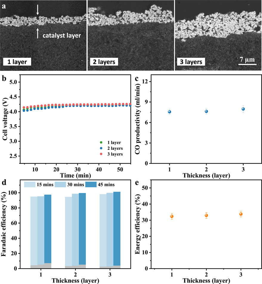
Figure 1. (a) Cross-sectional SEM images of Ag cathodes with different catalyst thickness. (b) Chronopotentiometry and (c) CO productivity. (d) Faradaic efficiency (blue for CO and grey for H2) and (e) CO energy efficiency at a working current density of 0.1 A/cm2. The experiments were performed at room temperature and atmospheric pressure with a CO2 flow rate of 90 sccm and anolyte of 1 M KHCO3.
At a fixed current density of 100 mA/cm2, the measured cell voltages are 4.10 V for the 1-layer sample, 4.06 V for 2-layer, and 4.14 V for 3-layer (Figure 1b). This negligible voltage variation suggests that the increase in catalyst layer thickness within this range does not significantly affect charge transport resistance or mass transport. The CO production rate is fairly stable, averaging between 8% and 9% from three consecutive measurements within 50 min (Figure 1c). Figure 1d presents the Faradaic efficiencies for each cathode sample over three consecutive 15-min intervals. The hydrogen FE exhibits a slight increase over time, indicating enhanced cathode wettability. In contrast, FECO remains stable over the same period, and increasing from 90.5% for the 1-layer sample to 95.4% for the 3-layer sample, suggesting improved accessibility of active sites at higher catalyst loadings. Similar operating voltage and high FECO keep the energy efficiency between 32.35% and 33.79% (Figure 1e). These observations align with prior findings in zero-gap configurations where catalyst layers of a few micrometers achieve efficient utilization without inducing significant diffusion barriers (Choi et al., 2022a; Blake et al., 2024). Weber et al. suggests that cCL thicknesses in the range of 2.5–25 µm have minimal impact on overall reaction efficiency (Weng et al., 2020), while experimental results indicate that FECO exceeds 90% only when the catalyst loading is significantly reduced to 0.01 mg/cm2 (Romiluyi et al., 2022). Nevertheless, a clear quantitative relationship between catalyst loading and CL thickness remains unestablished. Dinh et al. proved that a reasonable catalyst thickness can boost FECO, which is attributed to the high availability of active sites and improved CO2 adsorption (Dinh et al., 2018). Thicker catalyst layers may eventually introduce larger ohmic resistance or CO2 diffusion gradient (Qi et al., 2020; Choi et al., 2022a) that leads to a slightly higher voltage observed in 3-layer case here.
Stable high FECO (≥90%) and EECO (≥32%) across thickness variations indicate that CO2 transport and ion migration are sufficiently effective in this modified CEM-MEA system. From a techno-economic perspective, thinner catalyst layers, such as the 1-layer sample (3.2 µm thickness), can offer superior CO output per unit silver mass, improving cost efficiency and metal utilization. These results underscore the importance of optimizing catalyst thickness not only for electrochemical performance but also for cost-effectiveness and scalability in practical MEA-based CO2 electrolyzers.
Effect of CO2 flow rate
In dynamic electrochemical systems, particularly those operating under industrially relevant current densities, the ability to maintain stable performance across a wide range of CO2 flow rates is desirable. Several studies have evaluated the performance of CO2 electrolyzers within a relatively narrow range between 1 and 50 sccm (Ma et al., 2020; Corral et al., 2021; Sun et al., 2024). For example, Li et al. demonstrated that with a flow rate as low as 1 sccm, single-pass conversion could reach 90% in an acid-fed MEA system while Sinton et al. reported over 85% conversion at same low flow rate in alkaline conditions (O’Brien et al., 2021; Pan et al., 2022). However, while low flow rates are beneficial for CO2 utilization, this often limits the absolute productivity and is therefore not practical for scaled-up devices with large electrode areas (Cunha and Resasco, 2023). Therefore, extending the operating window to higher flow rates is crucial to bridge laboratory performance and industrial applications.
As the CO2 supply increases from 50 to 90 sccm, the LSV curve shifts to higher potentials, as shown in Figure 2a. Some works acknowledged that the increase in flow rate leads to microscopic changes in the local reaction environment and mass transfer path, which requires a higher electrode overpotential to maintain a fixed reaction rate, thereby increasing the voltage (Lu et al., 2017; Verma et al., 2017; Fan et al., 2024). Despite the rise in cell voltage, product selectivity and efficiency remain robust across the tested range. As shown in Figure 2b, FECO remains high at all tested flow rates despite a decrease in the CO fraction in the outlet stream, whereas the hydrogen Faradaic efficiency follows a non-monotonic trend, first declining and then recovering. To probe the interplay between convective transport, diffusion, and surface kinetics, key dimensionless parameters are evaluated and shown in Figure 2c. As flow increases from 50 to 90 sccm, Reynolds number rises but remains <2000, confirming laminar flow inside microchannels. Concurrently, the Sherwood number and mass transfer coefficient increase, enhancing the CO2 flux available to the GDL. Assuming CO2 flux through the porous GDL scales linearly with channel velocity, the Péclet number rises accordingly, reflecting increased convective transport and elevated CO2 concentration at the GDL–catalyst interface. At 50 sccm, mass transport limits surface CO2 availability, yielding a FECO of 88.5%. At 70 sccm, transport is no longer rate-limiting, producing a maximum FECO of 95.3%. Further increasing flow to 90 sccm slightly reduces FECO to 92.3%, as secondary factors such as local pH gradients, ion migration, and interfacial coverage variations increasingly modulate product distribution. These results reveal an optimal flow regime in which convective transport, diffusive flux, and surface reaction kinetics are synergistically balanced, maximizing CO selectivity and underscoring the critical role of mass transport–reaction coupling in electrochemical CO2 reduction. Eventually, energy efficiency remains relatively stable across the relatively high flow rate range (60–90 sccm), fluctuating only between 33.3% and 34.7%, as shown in Figure 2d. This demonstrates that while the electrical energy input increases slightly with higher flow rates, the overall system performance remains consistent, supporting the feasibility of broader operational flexibility in practical electrolysis setups. The optimal CO2 flow rate could be determined in accordance with system-specific parameters such as reactor geometry and electrode surface area (Ye et al., 2022; Subramanian et al., 2023). Proper adjustment ensures sufficient CO2 supply while avoiding excessive gas dilution. Ideally, achieving the target production rate with a lower fraction of unreacted CO2 in the outlet stream can reduce the need for gas recirculation and ease the burden of downstream gas purification.
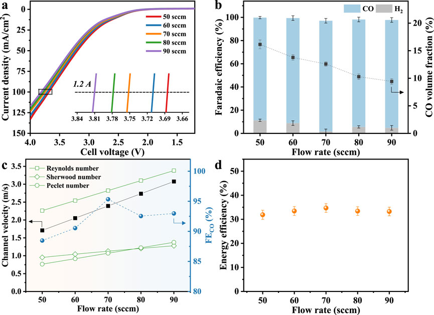
Figure 2. (a) LSV curves for different CO2 flow rates. (b) Volume fraction and productivity of CO and Faradaic efficiency. (c) Relationship between mass-transfer dimensionless numbers and flow rate, assuming the permeation flux through the porous GDL is 0.1 times the channel gas velocity. (d) Energy efficiency.
Effect of anolyte concentration
Under otherwise identical conditions, the composition of anolyte in the anode chamber directly influences electrolyte resistance and can also modulate the intrinsic kinetics of the oxygen evolution reaction (OER) at the anode (Larrea et al., 2022; Li et al., 2023; Xu et al., 2025). It also modifies key interfacial phenomena through ion gradients and transport kinetics (Wheeler et al., 2020). The LSV curves (Figure 3a) reveal that as the KHCO3 concentration increases from 0.1 M to 2.0 M, the current density at the equivalent voltage increases significantly. Sun et al. reported that higher anolyte concentrations enhance ionic conductivity, thereby reducing ohmic losses across the membrane and at the electrode-membrane interface (Xiao et al., 2022). As shown in Figure 3b, the cell voltage drops from over 4.45 V at 0.1 M to approximately 3.7 V at 2.0 M, indicating a substantial decrease in overall cell resistance. Beyond conductivity, increasing anolyte concentration also affects species transport across the membrane. More K+ ions migrate through the membrane toward the cathode, where they accumulate at the catalyst-electrolyte interface. Koper and co-workers have shown that such cation migration modifies local electric fields and enhances CO2 reduction by stabilizing key reaction intermediates, while concurrently suppressing HER through pH buffering and electrostatic effects (Monteiro et al., 2021). Here, this manifests as a steep improvement in FECO, rising from 34.4% at 0.1 M to 93.0% at 1.0 M (Figure 3c), accompanied by a sharp drop in hydrogen FE from 64.1% to below 5%. In addition, Zhu et al. observed improved selectivity with increased anolyte K+ content, even under acidic conditions, underscoring the role of alkali cations in tailoring the near-surface chemical environment to favor CO2 reduction (Li et al., 2023; Zhu et al., 2024).
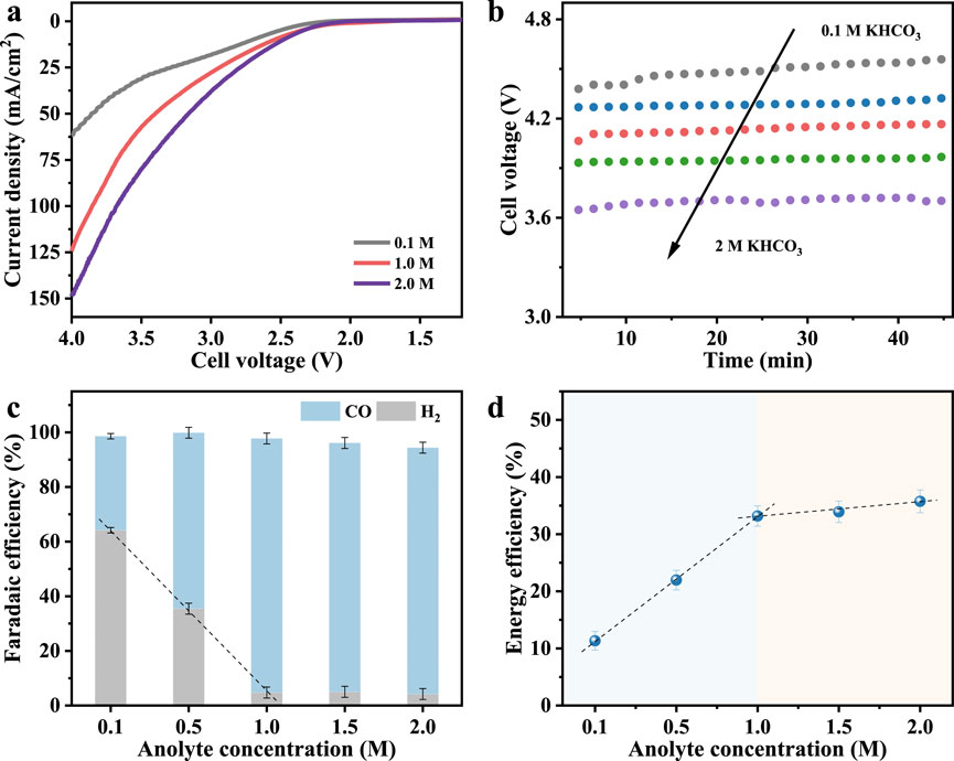
Figure 3. (a) LSV curves. (b) Chronopotentiogram, (c) Faradaic efficiency, and (d) energy efficiency of CO at a test current density of 0.1 A/cm2 with different concentrations of anolyte.
Additionally, the rise in CO energy efficiency from 11.3% at 0.1 M to 33.2% at 1.0 M (Figure 3d) further confirms the synergistic effect of enhanced conductivity and local reaction environment optimization. However, further increasing the KHCO3 concentration beyond 1.0 M yields marginal or no additional gains in FECO or energy efficiency. This saturation effect suggests that at sufficiently high ionic strength, ion transport is no longer rate-limiting. Moreover, elevated K+ concentrations can induce bicarbonate or carbonate salt precipitation within the porous gas diffusion layer, obstructing CO2 transport and degrading long-term performance (Garg et al., 2023). Therefore, optimizing anolyte concentration is essential: it must be high enough to ensure efficient ion transport and favorable interfacial conditions, but not so high as to induce salt accumulation or flooding, which compromise CO2 access and overall cell stability.
Effect of temperature
In practice, electrolyzer stacks may generate significant ohmic heat and therefore are commonly operated at 40 °C–70 °C (Pelzer et al., 2025). Temperature changes can directly affect the thermodynamic feasibility of electrochemical reactions and ionic conductivity while facilitating CO2 diffusion through the porous electrode (Choi et al., 2025). Recent studies have shown that elevated temperatures can significantly enhance reaction rates and reduce overpotentials of CO2RR as well as the resistance of Nafion membrane (Jiang et al., 2023; Rodriguez et al., 2024; Sakita and Ticianelli, 2025). For instance, Zhuang et al. developed an alkaline polymer electrolyte (APE)-based CO2RR system that employed pure water as the anolyte and achieved higher current density and Faradaic efficiency at operating temperatures above 60 °C (Yin et al., 2019). However, reduced CO2 solubility and inevitable water electrolysis at high temperature tends to shift products selectivity unless the electrode structure or membrane assembly suppresses those effects.
LSV results (Figure 4a) show that the current density increased significantly with temperature at all applied voltages, indicating enhanced reaction kinetics and system conductivity. The cell voltage required to sustain the current density of 0.1 A/cm2 drops from 4.1 V at 25 °C to 3.6 V at 50 °C and further to 3.4 V at 75 °C (Figure 4b), which is consistent with reduced ohmic resistance and improved ion conduction at high temperatures (Endrődi et al., 2020; Shafaque et al., 2021). Through modeling studies, Weber et al. demonstrated that the reduced overpotential resulted from the exponential enhancement of charge transfer kinetics with increasing temperature, in accordance with the Arrhenius relationship (Weng et al., 2019; Weng et al., 2020). The product distribution shows exceptional stability over the examined temperature range, as FECO rises slightly from 93.0% at 25 °C to 94.0% at 75 °C, while the competing HER exhibits only a modest increase from 4.7% to 6.8% within the same range (Figure 4c). Although also benefiting from thermodynamics, HER here is still effectively suppressed even at high temperatures. Segar et al. also observed unexpected inactive HER in an anion exchange membrane MEA system at high temperatures (>50 °C) and believed that fully humidified CO2 gas and increased carbonate solubility protected the cathode microenvironment for high selectivity of CO2RR (Rodriguez et al., 2024). Likewise, the zero-gap structure and excellent mass transport guarantee overwhelming CO2 adsorption and rapid CO desorption on the catalyst layer, and remove water transported from the more hydrated membrane at elevated temperature (Weng et al., 2019). Energy efficiency toward CO production increases from 33.2% at 25 °C to 40.3% at 75 °C (Figure 4d), which is mainly attributed to the significant decrease in operating voltage at higher temperatures due to the reduction in overall resistance, while maintaining high CO selectivity (She et al., 2024).
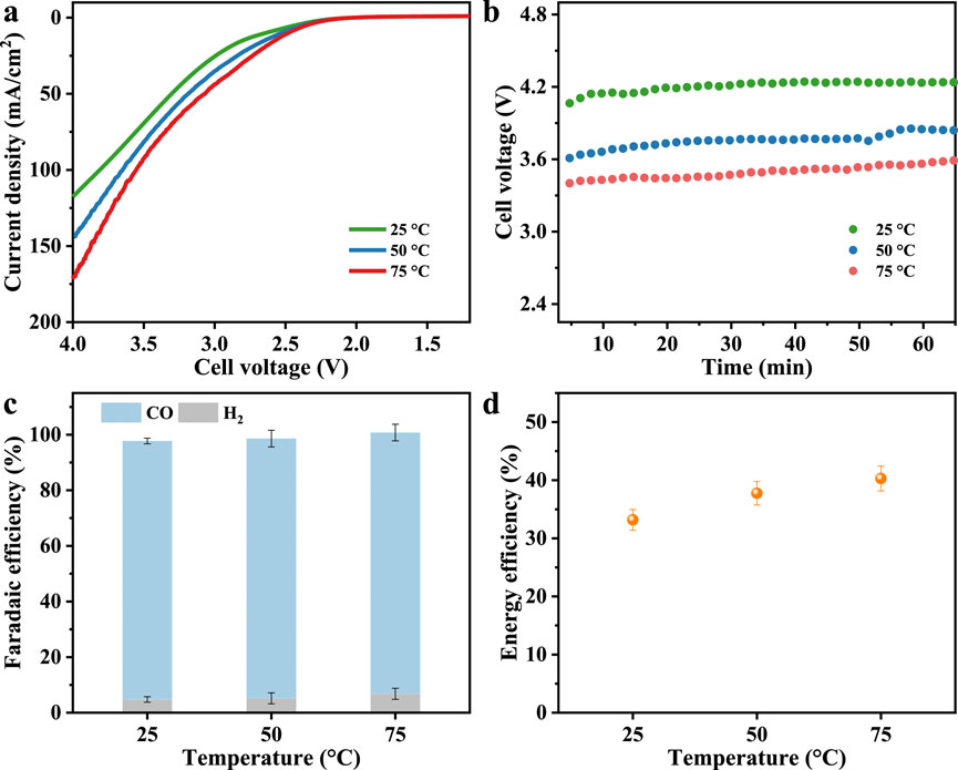
Figure 4. (a) LSV curves. (b) Chronopotentiogram, (c) Faradaic efficiency and (d) CO energy efficiency under different reaction temperatures at a constant current density of 0.1 A/cm2.
Moderately elevated temperatures in the range of 50 °C–75 °C can significantly enhance CO2 reduction performance in MEA systems by promoting reaction kinetics, ion diffusion and conductivity, and water transport. Nevertheless, operation at even higher temperatures and high current introduces challenges such as membrane dehydration and catalyst degradation, underscoring the importance of integrated thermal management strategies (Pelzer et al., 2025). Moving forward, the design of CO2 electrolysis systems should aim to optimize both thermal and electrochemical performance, with the potential to incorporate waste heat recovery from upstream or downstream industrial processes to further improve system efficiency.
Effect of pressure
Applying pressure will enhance CO2 solubility in aqueous electrolytes, substantially increasing reactant availability in liquid-fed cathode systems and thereby improving reaction rates and selectivity (Lamaison et al., 2020; Huang et al., 2023; Sun et al., 2025). In MEA systems, pressure acts differently by directly elevating the partial pressure of CO2 at the catalyst layer surface; despite this potential advantage, pressure effect on MEA-based CO2 reduction is understudied (Chen B. et al., 2024). Our study employs a zero-gap electrolyzer to assess how modest CO2 feed pressures (1–5 bar) influence the CO2RR at controlled conditions.
The LSV curves (Figure 5a) show that increasing gas feed pressure generally increases the reaction rate relative to ambient pressure operation, but no other significant differences are observed between 1 and 5 bar. This suggests that while slight pressurization increases CO2 availability at the catalyst interface, the overall reaction rate is still limited by other factors, such as intrinsic catalyst activity or membrane status under pressure. Despite this benefit, Figure 5b indicates that the production of CO in the outlet gas stream remained ∼8.5 mL/min across the pressure range studied. Figure 5c demonstrates that FECO rises to 94.7%–95.4% at pressurized conditions while the FE for H2 concurrently restrains to 3.1%–5.4%. The improved selectivity under pressurized conditions supports the hypothesis that enhanced CO2 transport through the GDE to the catalyst surface and increased surface coverage favors the CO2 reduction pathway (Hussain et al., 2025). It is noteworthy that although equal nominal pressures are applied to both the gas-phase cathode and liquid-phase anode compartments in this zero-gap system via a back-pressure regulator, the measured pressure on the anode side is approximately 0.2 bar higher than that on the cathode side. This pressure differential may induce liquid electrolyte migration across the membrane, potentially contributing to the occurrence of HER (Chen Y. et al., 2024). The energy efficiency of the system also benefits from pressurization, as shown in Figure 5d, where energy efficiency increased to approximately 36.5%. This enhancement results from the combined effects of increased FE and modest reductions in cell voltage losses due to improved mass transport and gas management under higher pressure conditions.
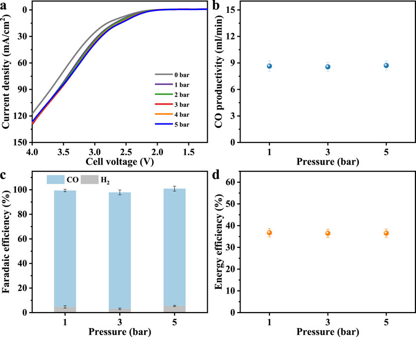
Figure 5. (a) LSV curves under different reaction pressure. (b) CO productivity, (c) Faradaic efficiency and (d) CO energy efficiency at a current density of 0.1 A/cm2.
This section demonstrates that slightly increased pressure can enhance CO2 mass transfer and product selectivity, thereby improving the overall efficiency and feasibility of zero-gap CEM-based electrolyzers. Higher pressure operation presents engineering challenges, such as increased mechanical stress on cell components, stringent sealing requirements, precise control and monitoring equipment, while pressure-dependent gas-liquid transfer dynamics may lead to changes in product distribution. Despite this, there is still much room for development in high-pressure electrocatalysis, especially when considering its integration with other industrial chemical production and processes.
In summary, the experimental parameters, corresponding variables, and their electrochemical performance are compiled in Table 1 to facilitate a direct and quantitative comparison. High energy efficiency can only be achieved by simultaneously maximizing product Faradaic efficiency and minimizing cell voltage; therefore, studies aiming to improve energy efficiency should primarily focus on optimizing both factors.
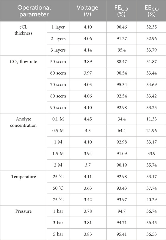
Table 1. Summary of CO2RR experimental performance at current density of 0.1 A/cm2. Unless otherwise stated, a standard experimental condition included a flow rate of 90 sccm, 1-layer catalyst coating, room temperature and ambient pressure, and 1.0 M KHCO3 solution as the anolyte.
Phenomenon of carbonate precipitation
High CO selectivity is maintained over a wide range of operating conditions; however, an unexpected pressure surge occurs after 60 min at ambient temperature and pressure due to white precipitate formation on the GDE backside (Figure 6), a phenomenon also observed in other MEA systems (Hernandez-Aldave and Andreoli, 2020; Disch et al., 2023; Park et al., 2023). This indicates that, despite employing a proton exchange membrane in a catholyte-free configuration, the cathode microenvironment alkalinizes as the reaction proceeds. High current densities enhance water uptake at the cathode GDE–CEM interface (Shafaque et al., 2020), promoting reactions between CO2 and water (CO2 + H2O+ 2e−→ CO + 2OH−, 2H2O+ 2e−→ H2 + 2OH−) transported from the membrane (Wheeler et al., 2020; Choi et al., 2022b). Strong CO2RR activity accelerates hydroxide generation, elevating local alkalinity and driving reactions with K+ migrating from the anode, leading to potassium (bi)carbonate (CO2 + OH− → HCO3−; HCO3− + OH− → CO32− + H2O) precipitation at the cathode (Garg et al., 2023; Bai et al., 2024). In a parallel study with the same zero-gap configuration and conditions but employing an anion exchange membrane, stable operation for over 100 h at 50 °C was achieved (Zhong et al., 2025a), underscoring the critical role of the cathode microenvironment in determining long-term stability. Although CEM primarily conducts protons, CO2RR-driven hydroxide buildup still renders the local environment alkaline, posing a fundamental constraint on extended operation. Despite this limitation, the early-stage performance provides a robust basis for elucidating the interplay between key operational parameters and catalytic behavior, which is the central focus of this study.
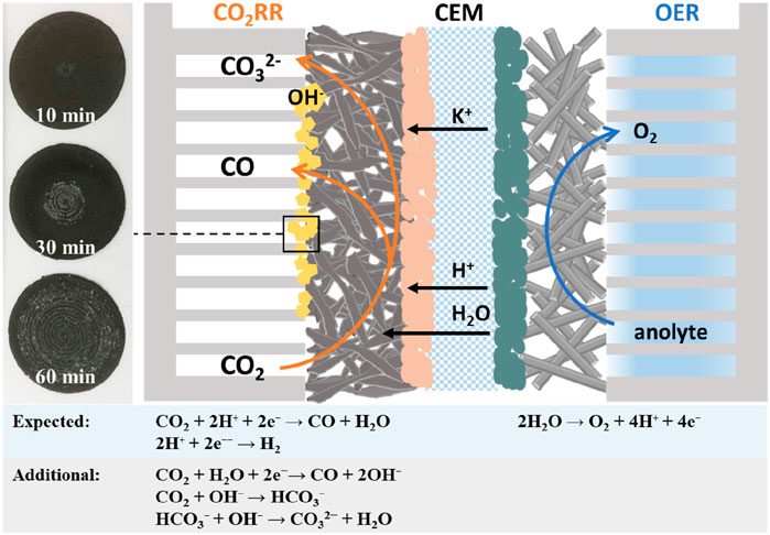
Figure 6. Optical photograph of the cathode backside and schematic diagram of the reactions.
This observation also highlights a dual nature of zero-gap electrolyzers. On one hand high selectivity is accessible due to efficient CO2 reduction under compact architecture. On the other hand, long-term stability is compromised by salt precipitation, which blocks gas diffusion pathways and degrades catalytic interfaces. Some studies addressed and investigated solutions to the salt precipitation problem. Burdyny et al. concluded several effective methods for mitigating salt precipitation, such as flushing, cation species and concentration design, and voltage pulses (Endrodi et al., 2021; Sassenburg et al., 2023). Recently, Wang et al. innovatively employed superhydrophobic cathode gas flow channels and acid-humidified CO2 gas, effectively extending operating time (Hao et al., 2025a; Hao et al., 2025b). These methods provide valuable guidance for future efforts to improve the durability of zero-gap CO2 electrolysis systems.
Conclusion
This study investigates the performance of electrochemical CO2 reduction to CO in a zero-gap electrolyzer utilizing cation exchange membranes, emphasizing the influence of key operational parameters such as catalyst loading, flow rate, temperature, pressure, and electrolyte concentration. The findings reveal that the reaction rate is predominantly limited by mass transport and catalyst utilization rather than catalyst quantity alone. A catalyst loading of 1.5 mg/cm2, corresponding to an approximate thickness of 3.2 µm, combined with a 1 M KHCO3 electrolyte, delivers efficient CO2 reduction performance. At a moderate current density of 100 mA/cm2, the system achieves over 90% FECO and exceeds 30% EECO across a wide flow rate range of 60–90 sccm. Under elevated pressures ranging from 1 to 5 bar, the energy efficiency reaches 36%, further increasing to above 40% at another temperature of 75 °C. Improvements in temperature and electrolyte concentration enhance ionic conductivity and reaction kinetics, while suitable flow rates and elevated pressures enhance mass transport and improve selectivity toward CO. In summary, balancing these factors is essential to boost CO2 electroreduction performance, with each parameter playing a distinct role in enhancing mass transport, catalytic effectiveness, or energy utilization efficiency.
Data availability statement
The original contributions presented in the study are included in the article/supplementary material, further inquiries can be directed to the corresponding author.
Author contributions
SZ: Writing – original draft, Validation, Conceptualization, Writing – review and editing, Methodology, Project administration, Supervision, Data curation. IA: Investigation, Data curation, Writing – review and editing. GH: Writing – review and editing, Investigation. PH: Supervision, Methodology, Writing – review and editing. SL: Conceptualization, Writing – review and editing. RD: Supervision, Resources, Funding acquisition, Project administration, Writing – review and editing.
Funding
The author(s) declare that financial support was received for the research and/or publication of this article. We gratefully acknowledge the financial support from the German Helmholtz Association within the Program: Materials and Technologies for the Energy Transition MTET (Topic 3: Chemical Energy Carriers) and Helmholtz Initiative Climate Adaptation and Mitigation HI-CAM II, Cluster I, Net Zero 2050.
Conflict of interest
The authors declare that the research was conducted in the absence of any commercial or financial relationships that could be construed as a potential conflict of interest.
Generative AI statement
The author(s) declare that no Generative AI was used in the creation of this manuscript.
Any alternative text (alt text) provided alongside figures in this article has been generated by Frontiers with the support of artificial intelligence and reasonable efforts have been made to ensure accuracy, including review by the authors wherever possible. If you identify any issues, please contact us.
Publisher’s note
All claims expressed in this article are solely those of the authors and do not necessarily represent those of their affiliated organizations, or those of the publisher, the editors and the reviewers. Any product that may be evaluated in this article, or claim that may be made by its manufacturer, is not guaranteed or endorsed by the publisher.
References
Bai, Q., Xiong, L., Zhang, Y., Ma, M., Jiao, Z., Lyu, F., et al. (2024). Salt precipitation and water flooding intrinsic to electrocatalytic CO2 reduction in acidic membrane electrode assemblies: fundamentals and remedies. EES Catal. 2 (6), 1228–1237. doi:10.1039/d4ey00170b
Blake, J. W., Haverkort, J. W., and Padding, J. T. (2024). Less is more: optimisation of variable catalyst loading in CO2 electroreduction. Electrochimica Acta 507, 145177. doi:10.1016/j.electacta.2024.145177
Brückner, S., Feng, Q., Ju, W., Galliani, D., Testolin, A., Klingenhof, M., et al. (2024). Design and diagnosis of high-performance CO2-to-CO electrolyzer cells. Nat. Chem. Eng. 1 (3), 229–239. doi:10.1038/s44286-024-00035-3
Chen, B., Feng, M., Chen, Y., Yang, J., and Liu, Y. (2024a). Performing electrocatalytic CO2 reduction reactions at a high pressure. Carbon Neutrality 3 (1), 31. doi:10.1007/s43979-024-00106-7
Chen, Y., Ma, T., Wang, F., and Liu, Y. (2024b). Effect of pressure on the gas diffusion electrodes during CO2 reduction reaction. Industrial and Eng. Chem. Res. 63 (35), 15546–15553. doi:10.1021/acs.iecr.4c02212
Choi, W., Choi, Y., Choi, E., Yun, H., Jung, W., Lee, W. H., et al. (2022a). Microenvironments of Cu catalysts in zero-gap membrane electrode assembly for efficient CO2 electrolysis to C2+ products. J. Mater. Chem. A 10 (19), 10363–10372. doi:10.1039/d1ta10939a
Choi, W., Park, S., Jung, W., Won, D. H., Na, J., and Hwang, Y. J. (2022b). Origin of hydrogen incorporated into ethylene during electrochemical CO2 reduction in membrane electrode assembly. ACS Energy Lett. 7 (3), 939–945. doi:10.1021/acsenergylett.1c02658
Choi, J., Lim, H., Surendran, S., Park, S., Shim, J., Jeong, G. H., et al. (2025). Harnessing electrochemical CO2 reduction and assisted water electrolysis via constrained thermodynamic modeling. Phys. Chem. Chem. Phys. 27 (33), 17198–17211. doi:10.1039/d5cp01408e
Corral, D., Feaster, J. T., Sobhani, S., DeOtte, J. R., Lee, D. U., Wong, A. A., et al. (2021). Advanced manufacturing for electrosynthesis of fuels and chemicals from CO2. Energy and Environ. Sci. 14 (5), 3064–3074. doi:10.1039/d0ee03679j
Cunha, S. C. d., and Resasco, J. (2023). Maximizing single-pass conversion does not result in practical readiness for CO2 reduction electrolyzers. Nat. Commun. 14 (1), 5513. doi:10.1038/s41467-023-41348-w
Dinh, C. T., Burdyny, T., Kibria, M. G., Seifitokaldani, A., Gabardo, C. M., Garcia de Arquer, F. P., et al. (2018). CO2 electroreduction to ethylene via hydroxide-mediated copper catalysis at an abrupt interface. Science 360 (6390), 783–787. doi:10.1126/science.aas9100
Disch, J., Bohn, L., Metzler, L., and Vierrath, S. (2023). Strategies for the mitigation of salt precipitation in zero-gap CO2 electrolyzers producing CO. J. Mater. Chem. A 11 (14), 7344–7357. doi:10.1039/d2ta09966g
Ehlinger, V. M., Lee, D. U., Lin, T. Y., Duoss, E. B., Baker, S. E., Jaramillo, T. F., et al. (2024). Modeling planar electrodes and zero-gap membrane electrode assemblies for CO2 electrolysis. ChemElectroChem 11 (7), e202300566. doi:10.1002/celc.202300566
Endrődi, B., Kecsenovity, E., Samu, A., Halmágyi, T., Rojas-Carbonell, S., Wang, L., et al. (2020). High carbonate ion conductance of a robust PiperION membrane allows industrial current density and conversion in a zero-gap carbon dioxide electrolyzer cell. Energy and Environ. Sci. 13 (11), 4098–4105. doi:10.1039/d0ee02589e
Endrodi, B., Samu, A., Kecsenovity, E., Halmagyi, T., Sebok, D., and Janaky, C. (2021). Operando cathode activation with alkali metal cations for high current density operation of water-fed zero-gap carbon dioxide electrolysers. Nat. Energy 6 (4), 439–448. doi:10.1038/s41560-021-00813-w
Fan, J., Pan, B., Wu, J., Shao, C., Wen, Z., Yan, Y., et al. (2024). Immobilized tetraalkylammonium cations enable metal-free CO2 electroreduction in acid and pure water. Angew. Chem. Int. Ed. Engl. 63 (9), e202317828. doi:10.1002/anie.202317828
Garg, S., Xu, Q., Moss, A. B., Mirolo, M., Deng, W., Chorkendorff, I., et al. (2023). How alkali cations affect salt precipitation and CO2 electrolysis performance in membrane electrode assembly electrolyzers. Energy and Environ. Sci. 16 (4), 1631–1643. doi:10.1039/d2ee03725d
Ge, L., Rabiee, H., Li, M., Subramanian, S., Zheng, Y., Lee, J. H., et al. (2022). Electrochemical CO2 reduction in membrane-electrode assemblies. Chem 8 (3), 663–692. doi:10.1016/j.chempr.2021.12.002
Hao, S., Elgazzar, A., Ravi, N., Wi, T.-U., Zhu, P., Feng, Y., et al. (2025a). Improving the operational stability of electrochemical CO2 reduction reaction via salt precipitation understanding and management. Nat. Energy 10 (2), 266–277. doi:10.1038/s41560-024-01695-4
Hao, S., Elgazzar, A., Zhang, S. K., Wi, T. U., Chen, F. Y., Feng, Y., et al. (2025b). Acid-humidified CO2 gas input for stable electrochemical CO2 reduction reaction. Science 388 (6752), eadr3834. doi:10.1126/science.adr3834
Hernandez-Aldave, S., and Andreoli, E. (2020). Fundamentals of gas diffusion electrodes and electrolysers for carbon dioxide utilisation: challenges and opportunities. Catalysts 10 (6), 713. doi:10.3390/catal10060713
Huang, L., Gao, G., Yang, C., Li, X. Y., Miao, R. K., Xue, Y., et al. (2023). Pressure dependence in aqueous-based electrochemical CO2 reduction. Nat. Commun. 14 (1), 2958. doi:10.1038/s41467-023-38775-0
Hursan, D., and Janaky, C. (2023). Operando characterization of continuous flow CO2 electrolyzers: current status and future prospects. Chem. Commun. 59 (11), 1395–1414. doi:10.1039/d2cc06065e
Hussain, M. S., Ahmed, S., Sun, C., Oh, H.-S., and Kim, J. (2025). Boosting electrochemical CO2 reduction to CO by regulating pressure in zero-gap electrolyzer. J. CO2Util. 100, 103179. doi:10.1016/j.jcou.2025.103179
Jiang, R. Z., Parameshwaran, V. S., Boltersdorf, J., and Baker, D. R. (2023). Copper-nanowires incorporated with silver-nanoparticles for catalytic CO2 reduction in alkaline zero gap electrolyzer. Acs Appl. Energy Mater. 6 (20), 10475–10486. doi:10.1021/acsaem.3c01605
Kas, R., Star, A. G., Yang, K. L., Van Cleve, T., Neyerlin, K. C., and Smith, W. A. (2021). Along the channel gradients impact on the spatioactivity of gas diffusion electrodes at high conversions during CO2 electroreduction. ACS Sustain. Chem. and Eng. 9 (3), 1286–1296. doi:10.1021/acssuschemeng.0c07694
Kibria, M. G., Edwards, J. P., Gabardo, C. M., Dinh, C. T., Seifitokaldani, A., Sinton, D., et al. (2019). Electrochemical CO2 reduction into chemical feedstocks: from mechanistic electrocatalysis models to system design. Adv. Mater. 31 (31), 1807166. doi:10.1002/adma.201807166
Ko, Y. J., Lim, C., Jin, J., Kim, M. G., Lee, J. Y., Seong, T. Y., et al. (2024). Extrinsic hydrophobicity-controlled silver nanoparticles as efficient and stable catalysts for CO2 electrolysis. Nat. Commun. 15 (1), 3356. doi:10.1038/s41467-024-47490-3
Lamaison, S., Wakerley, D., Blanchard, J., Montero, D., Rousse, G., Mercier, D., et al. (2020). High-current-density CO2-to-CO electroreduction on Ag-alloyed Zn dendrites at elevated pressure. Joule 4 (2), 395–406. doi:10.1016/j.joule.2019.11.014
Larrea, C., Torres, D., Avilés-Moreno, J. R., and Ocón, P. (2022). Multi-parameter study of CO2 electrochemical reduction from concentrated bicarbonate feed. J. CO2Util. 57, 101878. doi:10.1016/j.jcou.2021.101878
Lee, H., Kwon, S., Park, N., Cha, S. G., Lee, E., Kong, T. H., et al. (2024). Scalable low-temperature CO2 electrolysis: current status and outlook. JACS Au 4 (9), 3383–3399. doi:10.1021/jacsau.4c00583
Li, H., Li, H., Wei, P., Wang, Y., Zang, Y., Gao, D., et al. (2023). Tailoring acidic microenvironments for carbon-efficient CO2 electrolysis over a Ni–N–C catalyst in a membrane electrode assembly electrolyzer. Energy and Environ. Sci. 16 (4), 1502–1510. doi:10.1039/d2ee03482d
Li, J., Zhang, H., Luo, C., Cheng, D., Xu, W., and Lin, M. (2025). Non-isothermal CO2 electrolysis enables simultaneous enhanced electrochemical and anti-precipitation performance. Nat. Commun. 16 (1), 4181. doi:10.1038/s41467-025-59604-6
Lu, X., Leung, D. Y. C., Wang, H., and Xuan, J. (2017). A high performance dual electrolyte microfluidic reactor for the utilization of CO 2. Appl. Energy 194, 549–559. doi:10.1016/j.apenergy.2016.05.091
Lu, X., Zhou, C., Delima, R. S., Lees, E. W., Soni, A., Dvorak, D. J., et al. (2024). Visualization of CO2 electrolysis using optical coherence tomography. Nat. Chem. 16 (6), 979–987. doi:10.1038/s41557-024-01465-5
Ma, W., Xie, S., Liu, T., Fan, Q., Ye, J., Sun, F., et al. (2020). Electrocatalytic reduction of CO2 to ethylene and ethanol through hydrogen-assisted C–C coupling over fluorine-modified copper. Nat. Catal. 3 (6), 478–487. doi:10.1038/s41929-020-0450-0
Monteiro, M. C. O., Dattila, F., Hagedoorn, B., García-Muelas, R., López, N., and Koper, M. T. M. (2021). Absence of CO2 electroreduction on copper, gold and silver electrodes without metal cations in solution. Nat. Catal. 4 (8), 654–662. doi:10.1038/s41929-021-00655-5
Mot, B. D., Ramdin, M., Hereijgers, J., Vlugt, T. J. H., and Breugelmans, T. (2020). Direct water injection in catholyte-free zero-gap carbon dioxide electrolyzers. ChemElectroChem 7 (18), 3839–3843. doi:10.1002/celc.202000961
Nguyen, D. L. T., Kim, Y., Hwang, Y. J., and Won, D. H. (2019). Progress in development of electrocatalyst for CO2 conversion to selective CO production. Carbon Energy 2 (1), 72–98. doi:10.1002/cey2.27
O’Brien, C. P., Miao, R. K., Liu, S., Xu, Y., Lee, G., Robb, A., et al. (2021). Single pass CO2 conversion exceeding 85% in the electrosynthesis of multicarbon products via local CO2 regeneration. ACS Energy Lett. 6 (8), 2952–2959. doi:10.1021/acsenergylett.1c01122
Pan, B., Fan, J., Zhang, J., Luo, Y., Shen, C., Wang, C., et al. (2022). Close to 90% single-pass conversion efficiency for CO2 electroreduction in an acid-fed membrane electrode assembly. ACS Energy Lett. 7 (12), 4224–4231. doi:10.1021/acsenergylett.2c02292
Park, J., Ko, Y.-j., Lim, C., Kim, H., Min, B. K., Lee, K.-Y., et al. (2023). Strategies for CO2 electroreduction in cation exchange membrane electrode assembly. Chem. Eng. J. 453, 139826. doi:10.1016/j.cej.2022.139826
Park, J., Kim, E.-D., Kim, S., Lim, C., Kim, H., Ko, Y.-J., et al. (2024). Deriving an efficient and stable microenvironment for a CO2 MEA electrolyzer by reverse osmosis. ACS Energy Lett. 9 (7), 3342–3350. doi:10.1021/acsenergylett.4c00933
Pelzer, H. M., Kolobov, N., Vermaas, D. A., and Burdyny, T. (2025). Scaling and heating will drive low-temperature CO2 electrolysers to operate at higher temperatures. Nat. Energy 10 (5), 549–556. doi:10.1038/s41560-025-01745-5
Qi, Z., Biener, M. M., Kashi, A. R., Hunegnaw, S., Leung, A., Ma, S., et al. (2020). Electrochemical CO2 to CO reduction at high current densities using a nanoporous gold catalyst. Mater. Res. Lett. 9 (2), 99–104. doi:10.1080/21663831.2020.1842534
Rabiee, H., Ge, L., Zhang, X. Q., Hu, S. H., Li, M. R., and Yuan, Z. G. (2021). Gas diffusion electrodes (GDEs) for electrochemical reduction of carbon dioxide, carbon monoxide, and dinitrogen to value-added products: a review. Energy and Environ. Sci. 14 (4), 1959–2008. doi:10.1039/d0ee03756g
Reyes, A., Jansonius, R. P., Mowbray, B. A. W., Cao, Y., Wheeler, D. G., Chau, J., et al. (2020). Managing hydration at the cathode enables efficient CO2 electrolysis at commercially relevant current densities. ACS Energy Lett. 5 (5), 1612–1618. doi:10.1021/acsenergylett.0c00637
Rodriguez, C. A. G., Kani, N. C., Moss, A. B., Joensen, B. O., Garg, S., Deng, W., et al. (2024). Insights into zero-gap CO2 electrolysis at elevated temperatures. EES Catal. 2 (3), 850–861. doi:10.1039/d3ey00224a
Romiluyi, O., Danilovic, N., Bell, A. T., and Weber, A. Z. (2022). Membrane-electrode assembly design parameters for optimal CO2 reduction. Electrochem. Sci. Adv. 3 (1), e2100186. doi:10.1002/elsa.202100186
Sakita, A. M. P., and Ticianelli, E. A. (2025). The role of cation exchange membrane characteristics in CO2 electrolysis to CO using acid anolyte. Electrochimica Acta 509, 145308. doi:10.1016/j.electacta.2024.145308
Sassenburg, M., Kelly, M., Subramanian, S., Smith, W. A., and Burdyny, T. (2023). Zero-gap electrochemical CO2 reduction cells: challenges and operational strategies for prevention of salt precipitation. ACS Energy Lett. 8 (1), 321–331. doi:10.1021/acsenergylett.2c01885
Segets, D., Andronescu, C., and Apfel, U. P. (2023). Accelerating CO2 electrochemical conversion towards industrial implementation. Nat. Commun. 14 (1), 7950. doi:10.1038/s41467-023-43762-6
Shafaque, H. W., Lee, C., Fahy, K. F., Lee, J. K., LaManna, J. M., Baltic, E., et al. (2020). Boosting membrane hydration for high current densities in membrane electrode assembly CO2 electrolysis. Acs Appl. Energy Mater. 12 (49), 54585–54595. doi:10.1021/acsami.0c14832
Shafaque, H. W., Lee, J. K., Krause, K., Lee, C., Fahy, K. F., Shrestha, P., et al. (2021). Temperature enhances the ohmic and mass transport behaviour in membrane electrode assembly carbon dioxide electrolyzers. Energy Convers. Manag. 243, 114302. doi:10.1016/j.enconman.2021.114302
She, X., Zhai, L., Wang, Y., Xiong, P., Li, M.M.-J., Wu, T.-S., et al. (2024). Pure-water-fed, electrocatalytic CO2 reduction to ethylene beyond 1,000 h stability at 10 A. Nat. Energy 9 (1), 81–91. doi:10.1038/s41560-023-01415-4
Siegmund, D., Metz, S., Peinecke, V., Warner, T. E., Cremers, C., Greve, A., et al. (2021). Crossing the valley of death: from fundamental to applied research in electrolysis. JACS Au 1 (5), 527–535. doi:10.1021/jacsau.1c00092
Subramanian, S., Yang, K., Li, M., Sassenburg, M., Abdinejad, M., Irtem, E., et al. (2023). Geometric catalyst utilization in zero-gap CO2 electrolyzers. ACS Energy Lett. 8 (1), 222–229. doi:10.1021/acsenergylett.2c02194
Sun, M., Cheng, J., and Yamauchi, M. (2024). Gas diffusion enhanced electrode with ultrathin superhydrophobic macropore structure for acidic CO2 electroreduction. Nat. Commun. 15 (1), 491. doi:10.1038/s41467-024-44722-4
Sun, R., Zhao, J., Liu, H., Xue, Y., and Lu, X. (2025). Pressure regulated CO2 electrolysis on two-dimensional Bi2O2Se. Chem. Commun. 61 (10), 2071–2074. doi:10.1039/d4cc05357e
Verma, S., Hamasaki, Y., Kim, C., Huang, W., Lu, S., Jhong, H. M., et al. (2017). Insights into the low overpotential electroreduction of CO2 to CO on a supported gold catalyst in an alkaline flow electrolyzer. ACS Energy Lett. 3 (1), 193–198. doi:10.1021/acsenergylett.7b01096
Wang, M., Lin, L., Zheng, Z., Jiao, Z., Hua, W., Wang, G., et al. (2023). Hydrophobized electrospun nanofibers of hierarchical porosity as the integral gas diffusion electrode for full-pH CO2 electroreduction in membrane electrode assemblies. Energy and Environ. Sci. 16 (10), 4423–4431. doi:10.1039/d3ee01866k
Weng, L., Bell, A. T., and Weber, A. Z. (2019). Towards membrane-electrode assembly systems for CO2 reduction: a modeling study. Energy and Environ. Sci. 12 (6), 1950–1968. doi:10.1039/c9ee00909d
Weng, L.-C., Bell, A. T., and Weber, A. Z. (2020). A systematic analysis of Cu-based membrane-electrode assemblies for CO2 reduction through multiphysics simulation. Energy and Environ. Sci. 13 (10), 3592–3606. doi:10.1039/d0ee01604g
Wheeler, D. G., Mowbray, B. A. W., Reyes, A., Habibzadeh, F., He, J. F., and Berlinguette, C. P. (2020). Quantification of water transport in a CO2 electrolyzer. Energy and Environ. Sci. 13 (12), 5126–5134. doi:10.1039/d0ee02219e
Xiao, T., Ma, Y., Zeng, S., Yao, X., Ye, T., Li, H., et al. (2022). Proton antagonist membrane towards exclusive CO2 reduction. Nano Res. 16 (4), 4589–4595. doi:10.1007/s12274-022-5067-y
Xu, Q., Joensen, B. O., Kani, N. C., Sartori, A., Willson, T., Varcoe, J. R., et al. (2025). Electrolyte effects in membrane-electrode-assembly CO electrolysis. Angew. Chem. Int. Ed. Engl. 64 (22), e202501505. doi:10.1002/anie.202501505
Ye, K., Zhang, G., Ma, X., Deng, C., Huang, X., Yuan, C., et al. (2022). Resolving local reaction environment toward an optimized CO2 -to-CO conversion performance. Energy and Environ. Sci. 15 (2), 749–759. doi:10.1039/d1ee02966e
Yin, Z. L., Peng, H. Q., Wei, X., Zhou, H., Gong, J., Huai, M. M., et al. (2019). An alkaline polymer electrolyte CO2 electrolyzer operated with pure water. Energy and Environ. Sci. 12 (8), 2455–2462. doi:10.1039/c9ee01204d
Zhong, S. Y., Sui, P. F., Holtappels, P., Navarrete, A., Li, F. W., and Dittmeyer, R. (2025a). Robust and efficient electroreduction of CO2 to CO in a modified zero-gap electrochemical cell. Chem. Eng. J. 244, 161119. doi:10.1016/j.cej.2025.161119
Zhong, S. Y., Yang, W. W., Liu, S. D., and Dittmeyer, R. (2025b). Synergistic electroreduction of CO2 to C1-C3 gas products in a pressure-tolerant MEA system. Int. J. Hydrogen Energy 119, 73–81. doi:10.1016/j.ijhydene.2025.03.234
Keywords: electrocatalysis, CO2 reduction, productivity, energy efficiency, multiparameter study
Citation: Zhong S, Ait Aissa I, Huang G, Holtappels P, Liu S and Dittmeyer R (2025) Experimental study of operating parameters in zero-gap CO2 electrolysis. Front. Catal. 5:1657848. doi: 10.3389/fctls.2025.1657848
Received: 01 July 2025; Accepted: 08 September 2025;
Published: 19 September 2025.
Edited by:
Valentín Briega-Martos, Cornell University, United StatesReviewed by:
Yashwant Bisht, Uttaranchal University, IndiaCristina González-Fernández, University of Cantabria, Spain
Copyright © 2025 Zhong, Ait Aissa, Huang, Holtappels, Liu and Dittmeyer. This is an open-access article distributed under the terms of the Creative Commons Attribution License (CC BY). The use, distribution or reproduction in other forums is permitted, provided the original author(s) and the copyright owner(s) are credited and that the original publication in this journal is cited, in accordance with accepted academic practice. No use, distribution or reproduction is permitted which does not comply with these terms.
*Correspondence: Siyu Zhong, c2l5dS56aG9uZ0BraXQuZWR1