 Alexsander Luiz Quintão1Brunella Bermudes Prati Sant’ana1Francisco Mello Fonseca1Pedro Rosseto de Faria2
 José Joaquim Conceição Soares Santos1*
- 1Department of Mechanical Engineering, Federal University of Espirito Santo (UFES), Vitoria, Espirito Santo, Brazil
- 2Railways Department, Federal Institute of Espírito Santo (IFES), Cariacica, Espírito Santo, Brazil
Energy efficiency is a critical factor in the transition toward sustainable energy systems and the decarbonization of industrial processes. In this context, the recovery of residual process energy represents a key strategy. This study presents a case analysis of a Brazilian carbo-chemical plant, where calcination furnaces release exhaust gases containing both thermal and chemical energy. These gases, generated by six furnaces, have a total flow rate of 1.36 kg/s at 800 °C and a volumetric composition of 26% H2, 4.2% CH4, and 5% CO, among other components, resulting in a total energy potential of 8.30 MW—comprising 1.63 MW of thermal and 6.67 MW of chemical energy. The main objective of this study is to assess the potential for recovering this energy through various cogeneration system configurations based on steam cycles, aimed at process thermal oil heating and electricity generation. Simulations were conducted using IPSEpro 8.0, and system performance was evaluated according to the First and Second Laws of Thermodynamics to identify opportunities for optimization. The results show that, in addition to providing 70 kW of useful heat for oil heating, the system can deliver up to 2.65 MW of electrical power. The energy and exergy efficiencies of the steam cycles reach 43.35% and 80.45%, respectively, while the overall system achieves energy and exergy efficiencies of 32.8% and 32.03%. Exergy analysis highlights areas for improvement, particularly in combustion and heat exchange, due to high irreversibilities in combustion chambers and boilers (up to 821.50 kW and 3384.29 kW, respectively) and recoverable heat present in boiler exhaust gases. Environmental analysis indicates a significant reduction in stack gas temperatures (66%–77% relative to the initial 800 °C) and the combustion of residual fuel components, especially CH4, which markedly decreases thermal and chemical pollution. Quantitatively, electricity generation reduces grid dependency, preventing up to 3234 tons of CO2 emissions per year. These findings demonstrate a considerable theoretical estimable potential for residual energy recovery, yielding substantial improvements in efficiency and environmental impact mitigation. Furthermore, an optimized technological approach could achieve energy efficiencies of up to 50%, producing 40% more electricity. These results highlight the importance of further studies, particularly to evaluate economic feasibility and potential integration into carbon markets.
1 Introduction
The increasing concern regarding energy scarcity and environmental challenges, such as carbon emissions and greenhouse gases (GHG), has garnered significant interest in sustainable energy recovery, particularly within industrial processes. Heightened awareness of climate change has also prompted the establishment of new regulatory frameworks across various nations and industries (Ng et al., 2020). According to Iglesias Garcia et al. (2018), approximately 52% of the primary energy consumed worldwide is lost during fuel combustion and heat transfer processes. The implementation of technologies that capture and reuse this waste energy can enhance energy efficiency, contributing to the sustainability of the sectors. The International Energy Agency-IEA (2021) has projected that between 2022 and 2035, global energy demand will increase by one-third. In this context, electricity demand alone accounts for more than half of the overall rise in global energy consumption.
Industries are widely recognized as significant consumers of electricity. Given the wide range of available technologies for energy management, residual energy recovery systems are pivotal in reducing specific electricity consumption. In this framework, various thermodynamic cycles have been studied and combined to maximize system efficiency, enabling the generation of two or more forms of energy within a single system. Thus, it is evident that implementing strategies to improve energy efficiency in production processes is essential for reducing operational costs and increasing competitiveness, particularly in the context of global economic decarbonization. Moreover, these strategies promote efforts to mitigate environmental impacts, such as reducing GHG emissions (World Steel Association, 2024). Considering the significant electricity consumption in industries, implementing measures that encourage the recovery of wasted residual energy is economically advantageous, given its potential to generate useful work (Çengel et al., 2023).
Although industries require high levels of energy, it is well known that not all available energy is converted into useful work. Unused energy is lost during industrial processes due to inefficiencies in energy conversion. For instance, residual energy, which possesses thermal and sometimes chemical value, represents an underutilized energy source originating from various processes. Similar to chemical pollution, thermal pollution exerts a substantial impact on the environment. Industrial processes generate a considerable amount of heat through equipment such as furnaces and boilers. However, only a fraction of this energy is utilized, while the remainder is dissipated through various heat transfer mechanisms (Silva, 2016).
The loss of energy in the form of heat influences the overall production costs of consumer goods, as these costs are dictated by energy expenditures. Consequently, in cases where direct utilization of heat is unfeasible, it becomes imperative to assess the potential for its conversion into electricity, a more transportable and economically valuable form of energy compared to thermal energy.
Heat recovery systems can serve as a tool for reducing energy consumption in industrial settings. By converting waste heat into useful energy forms, such as electricity or process heat, not only is the environmental impact of heat dissipation mitigated, but additional GHG emissions associated with conventional energy production are also reduced. Achieving this objective necessitates the identification of residual heat sources and the selection of the most suitable recovery technology (Brückner et al., 2015).
Cogeneration systems (also known as Combined Heat and Power - CHP) are widely used for energy recovery. It utilizes a single fuel source to simultaneously generate electricity and useful heat. Instead of wasting the heat produced during electricity generation, it is recovered and repurposed for industrial processes, heating, or cooling. It is worth emphasizing that, from an environmental perspective, cogeneration systems can play a significant role in the energy sector. The environmental factor should be considered a key advantage of CHP systems, particularly concerning CO2 emissions, which are the main contributors to the greenhouse effect (Feidt and Costea, 2012). Furthermore, cogeneration can contribute to reducing fuel consumption while maintaining the same level of production, thereby leading to a decrease in harmful emissions and GHGs, ultimately resulting in a lower environmental impact (Frangopoulos, 2017). The primary objective of cogeneration is to enhance energy generation efficiency and optimize the utilization of available energy resources. Typically, the waste heat is repurposed to fulfill thermal demands, either for heating applications or for power generation. Various cogeneration-based heat recovery systems have been studied and implemented within industrial settings. The utilization of gases emitted from industrial furnaces represents a promising energy source.
Numerous researchers have concentrated their efforts on decarbonization and energy transition, exploring solutions aimed at reducing carbon emissions and fostering the adoption of sustainable energy sources. Among the strategies investigated, waste heat recovery from industrial processes has emerged as an effective approach. This method entails capturing and repurposing heat that would otherwise be lost in industrial operations, converting it into usable energy. Among the numerous studies and applications in the field, a few can be highlighted herein to confirm the theoretical and practical relevance of the topic. For instance, Oyedepo and Fakeye (2021) examined waste heat recovery technologies as a pathway toward sustainability and energy development and concluded that a substantial portion of waste heat can be technically and economically recovered through sustainable technologies. In a study by Zhang et al. (2020), a cascade heating system was proposed for waste heat recovery in a cogeneration plant, integrating it with a steam vacuum pump. Lemos et al. (2021) conducted an energy and exergy analysis of a power generation cycle utilizing blast furnace gases from a steel mill. Rohde et al. (2020) investigated energy recovery from residual gas in three-phase electric furnaces employed in silicon production.
In order to emphasize the significance of this topic and underscore the substantial interest within the academic community, one may reference studies on losses in thermoelectric plants and potential strategies for energy reuse (Ahmadi and Toghraie, 2016; Shamet et al., 2021); research on heat recovery from exhaust gases of electric arc furnaces for steam generation (Gandt et al., 2016); analyses of thermal energy storage aimed at enhancing residual energy recovery from a silicon plant in Norway (Rohde et al., 2022); and concerning different kind of cogeneration with heat recovery (Nikafshan Rad et al., 2024; Pawlenka et al., 2023; Prestipino et al., 2025) all sharing the common goal of identifying optimal energy and environmental solutions.
From this perspective of energy recovery and environmental problem mitigation, the present study focuses on the thermodynamic modeling of five cogeneration configurations integrated with the conventional Rankine cycle, aiming to recover energy potential from the exhaust gases emitted by the chimneys of six electric calcination furnaces. These furnaces belong to a carbo-chemical plant located in the city of Serra, Brazil, specialized in the production of carbon pastes and blocks for the foundry industry. This paste is utilized in furnaces for metal reduction and metallic silicon production. For these simulations, the work of Rohde et al. (2020) was used as a reference, from which four different configurations were proposed, analyzed, and compared.
During the production process, anthracite (raw material) undergoes calcination (a heat treatment) conducted in specialized calcination furnaces, emitting gases (1.36 kg/s) that contain both thermal (800 °C) and chemical (due to the presence of CO2, CH4, CO) energies, with a recovery potential of 8.30 MW. This residual energy can be recovered and utilized for both electricity generation and thermal energy consumption within the industrial processes. The utilization of these two energy potentials—particularly the chemical component, which primarily consists of greenhouse gases (CO2, CH4, CO, among others)—not only enhances the plant’s energy efficiency but also contributes to the chemical treatment of these emissions. This aligns with both national and international carbon neutrality goals, thereby reducing atmospheric pollutant emissions.
Furthermore, the efficiency of each proposed system is evaluated. The thermodynamic software IPSEpro 8.0 (Simtechnology, 2024) was employed to determine electrical power generation in the generators and the thermal energy output in heat exchangers for process thermal oil heating. These results facilitated the calculation of cycle efficiencies and overall cogeneration performance. Ultimately, a comparative thermodynamic analysis is conducted, elucidating the distinctive characteristics of each system. Besides, a preliminary environmental analysis is carried out by estimating the avoided emissions associated with electricity generation in each investigated configuration. For this purpose, data on the CO2 emission factor for electricity generation in Brazil provided by the National Emissions Registry System–SIRENE (Ministério da Ciência, 2024), were employed.
The novelty of this article lies in the fact that, although it uses Rohde et al. (2020) as a reference, it advances the analysis and thus contributes new perspectives to the field. While Rohde et al. (2020) focused on comparing the operational aspects of a carbo-chemical plant that produces both power and district heating, our paper concentrates on the design-point analysis, comparing the energy and exergy efficiencies of cogeneration cycle configurations with steam turbines, in addition to conducting an environmental assessment based on avoided emissions.
Moreover, this study provides insights suggesting that alternative technological pathways may be explored for energy recovery through more efficient systems.
2 Case study
The case study was carried out in a Brazilian carbo-chemical industry, and the following sections detail the methodology employed to evaluate the energy recovery potential of its exhaust gases.
2.1 Calcination process
Calcination is a thermal process in which a material is heated to high temperatures, typically in the absence of oxygen, to remove impurities, decompose chemical compounds, or modify its physical and chemical properties. This process is widely used in industries such as carbo-chemistry, metallurgy, and cement production. In the carbo-chemical industry, electric calcination furnaces are employed in the thermal treatment of mineral coal, coke, and other carbon-based materials used in the manufacturing of advanced materials.
The electric calcination process employs raw anthracite as the primary feedstock to produce Electrically Calcined Anthracite (ECA), consuming electricity and generating exhaust gases, as illustrated in Figure 1. This process involves heating anthracite to temperatures ranging from 1000 °C to 3000 °C while applying an electric current between two graphite electrodes. The primary objectives of this treatment include the removal of volatile compounds, reduction of impurities, and enhancement of electrical conductivity. The calcination temperature is a determining factor, as it governs the thermal decomposition of grains, crystalline phase transitions, and the extent of graphitization in mineral coal. These transformations reduce electrical resistivity, increase Young’s modulus, and enhance compressive strength, thereby yielding ECA with superior conductivity and mechanical performance. Previous studies, such as those by Tumidajski et al. (1996) and Gasik et al. (2010), provide detailed analyses of these phenomena.
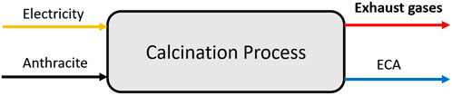
Figure 1. Calcination flow.
The calcination furnaces (Figure 2) are equipped with two graphite electrodes, positioned at the top and bottom. Each furnace operates with an active power of 1000 kW and processes an anthracite feed rate of 1200 kg/h. The calciner’s output is regulated at 950 kg/h of ECA. Under these operating conditions, the total volume of gases emitted through the chimney is 1.36 kg/s at a temperature of 800 °C. The Brazilian industrial unit operates with six electric calciners (Figure 2) and their furnaces operate in a continuous mode, with each furnace having its own dedicated feeding system and an individualized exhaust system. Raw anthracite is introduced at the top of the furnace through feeding trays and flows downward by gravity into the equipment, where two electrodes (upper and lower) conduct the electric current. At the end of the process, the raw anthracite, now transformed into ECA, is discharged at the furnace outlet.
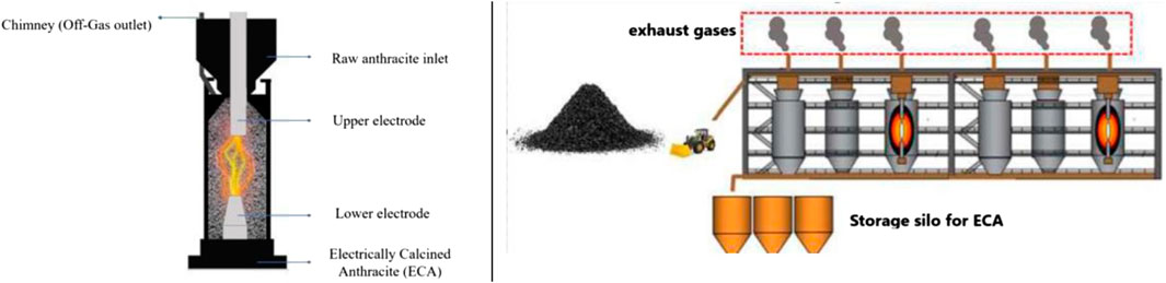
Figure 2. Electric calciner.
The carbo-chemical company analyzed in this study operates six electric calcination furnaces, with an annual availability rate of 80%. Throughout the production process, the composition of anthracite remains consistent across all furnaces. The exhaust gases generated during the calcination of mineral coal constitute a complex mixture of various chemical elements. This process involves heating coal in an environment with minimal or no oxygen, leading to the release of gases such as carbon dioxide (CO2), carbon monoxide (CO), methane (CH4), hydrogen (H2), volatile hydrocarbons, and sulfur compounds, including sulfur dioxide (SO2). Furthermore, calcination may result in the emission of fine particulate matter and ash. The composition of the gases, made available by the plant through monitoring conducted in 2024, was characterized by sampling at the upper dome of the furnace prior to their release into the atmosphere and typically includes 26% H2, 4.2% CH4, and 5% CO.
The lower heating value (LHV) quantifies the energy released as heat during the combustion of a unit mass or volume of fuel, excluding the energy retained in water vapor. In the case of exhaust gases from electric calcination furnaces, the LHV generally ranges between 4000 kJ/kg and 7000 kJ/kg.
2.2 Industrial data collection: thermal fluid parameters
This study’s data collection process was designed to obtain real operational data from the carbo-chemical plant. The thermodynamic calculations for the facility were performed based on Rohde et al. (2020) and the parameters provided by the company regarding the exhaust gases (mass flow rate, temperature, and composition). In the industrial plant examined, a Therminol-type thermal fluid is utilized for heating mixer lines and molding hoppers. Currently, these thermal oils are heated using two inductive heating systems, each with a power capacity of 35 kW. The thermal fluid enters the heating equipment at a flow rate of 0.1128 kg/s and an initial temperature of 50 °C. It is subsequently heated to a temperature of 300 °C, maintaining the same flow rate before being distributed to the respective systems.
2.3 Thermodynamic modeling: IPSEpro software and boundary conditions
IPSEpro 8.0 software (Simtechnology, 2024) was used to model five configurations, simulating industrial processes via heat and mass balance calculations. Due to incompatibility between the Advanced Power Plant (APP) and Concentrated Solar Power (CSP) libraries, two separate simulations were needed to analyze exhaust gas combustion and cogeneration capacity. Data transfer between simulations enabled an integrated plant performance evaluation. Simulation necessitates the availability of critical input data, including process-related parameters as well as general ambient and boundary conditions applicable to all five configurations, as presented in Table 1. To assess the performance of devices (evaporators, turbines, and heat exchangers) it is essential to apply both the First and Second Law of Thermodynamics.
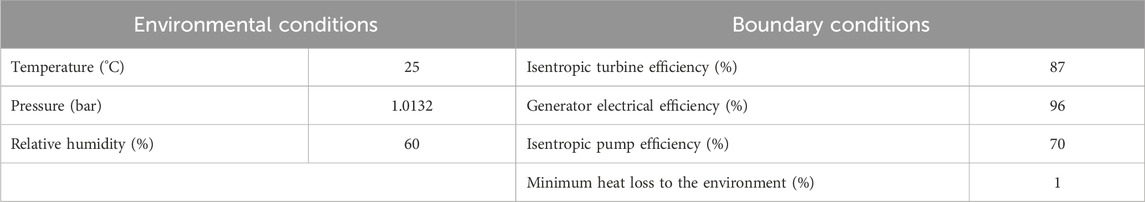
Table 1. Modeling conditions in IPSEPRO.
Based on the simulations conducted in IPSEpro 8.0, detailed point-by-point data were extracted for pressure (p), temperature (T), mass flow rate (
2.4 Environmental assessment
In addition to the thermodynamic analysis, this study includes an environmental assessment of avoided CO2 emissions. To this end, the amount of CO2 that would not be emitted if the electricity generated through cogeneration in the power cycle were used internally rather than drawn from the electrical grid is calculated. This calculation is performed by multiplying the CO2 emission factor for electricity generation in Brazil by the net power and useful heat produced for each configuration, yielding a value in tons per hour (ton/h). This hourly value is then extrapolated over the total number of hours in a year (8760 h) to obtain the annual avoided emissions in tons per year.
The CO2 emission factor for electricity generation in Brazil, spanning the period from 2011 to 2023 and provided by the National Emissions Registry System–SIRENE (Ministério da Ciência, 2024) is shown in Figure 3. According to Espírito Santo’s Decarbonization and GHG Emissions Neutralization Plan (Governo do Estado do Espírito, 2023) emissions associated with electricity imports are determined by the composition of the national generation matrix and are influenced by the operational requirements of thermoelectric plants to meet domestic demand, which accounts for the observed interannual variability.
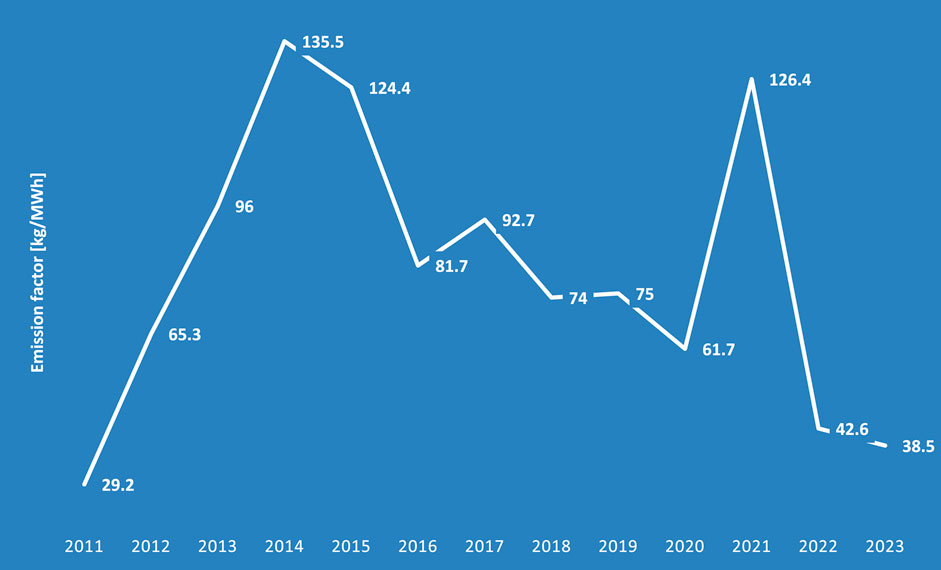
Figure 3. CO2 emission factor for electricity generation in Brazil (Ministério da Ciência, 2024).
2.5 Thermodynamic configurations
Starting from a baseline configuration, referred here as Configuration 0, four derived configurations are proposed and analyzed. Configuration 0 represents the baseline case (Rohde et al., 2020), which utilizes and analyzes gases from electric furnaces. Building on this baseline, four additional configurations (1–4) are proposed and investigated. These configurations (1–4) are applied to assess the recovery of exhaust gases generated during the calcination process in a Brazilian carbo-chemical industry. The main characteristics and differences of these five configurations are described in Subsections 2.5.1 to 2.5.5.
It is important to emphasize that the plant analyzed in this study (Configurations 1–4) operates within the carbon and specialty pulp industry, employing electric furnaces for the thermal treatment of one of its raw materials. This contrasts with the plant investigated by Rohde et al. (2020) – Configuration 0, which focuses on metallic silicon production. Furthermore, the present study highlights a design-point analysis, assessing the energy and exergy efficiencies of cogeneration cycle configurations with a steam turbine, whereas Rohde et al. (2020) primarily addresses the operational aspects of the plant.
2.5.1 Configuration 0
The configuration is based on the study by Rohde et al. (2020), who conducted a similar analysis on a plant belonging to the same carbo-chemical group examined in this work. Figure 4 presents this configuration simulated in IPSEpro 8.0. Residual gases from two silicon furnaces (a) are directed through a common boiler system, which generates steam (b) to power a steam turbine and export heat to the local district heating network (e).
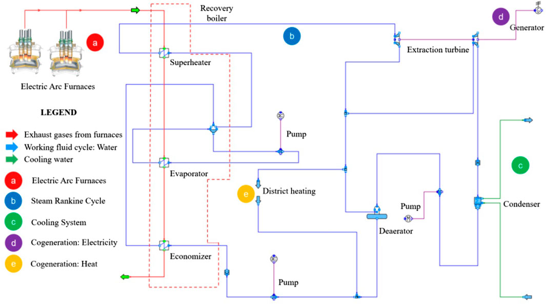
Figure 4. Modeling of Configuration 0.
The heat recovery system was designed to operate at 62 bar but is operated at 55 bar to reduce leakage. The isentropic efficiency of the turbine is 0.87, and the nominal values for the simulation were set at 46 bar for inlet pressure, 10 bar for outlet pressure, and 20 kg/s for steam mass flow, based on measurement data. The condensation pressure was considered constant and defined at 0.06 bar. Further details and data can be found in Rohde et al. (2020). In the system (Figure 4) The steam (b) expands in the turbine and drives the electric generator to generate electricity (d). After passing through the high-pressure turbine, steam is extracted based on the heat demand required for district heating (e), as well as for feedwater preheating. The selection of extraction turbine technology was guided by several factors. First, the decision was made to utilize the same technology employed by Rohde et al. (2020). Second, backpressure turbines are generally used when the objective is to generate low power while producing a large amount of heat. In the present study, the useful heat output of the thermal oil system is 70 kW (energy-based), which does not justify the use of backpressure turbines, as it does not align with the desired generation profile.
2.5.2 Configuration 1
Configuration 1, depicted in Figure 5, introduces several modifications to Configuration 0, affecting both the cycle and the system. In Configuration 1, the thermodynamic cycle benefits from the implementation of a cooling tower instead of seawater cooling. Additional modifications include utilizing the cogenerated heat for heating industrial thermal oil for internal use and sourcing exhaust gases from electric calcination furnaces (Figure 2), thereby harnessing thermal energy. Configuration 1 follows a topping cycle, with both cogenerated products being used internally within the industrial plant.
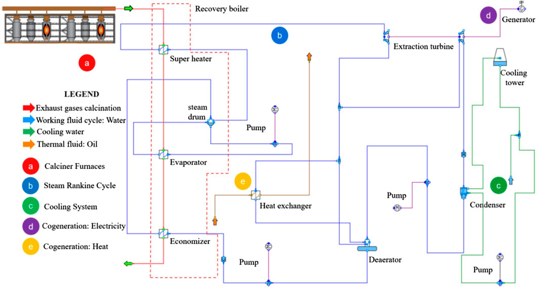
Figure 5. Modeling of Configuration 1.
The system begins with the exhaust gases from the furnaces (a) entering the heat recovery boiler in a counterflow arrangement, where they transfer heat to the saturated steam in the superheater, converting it into superheated steam for expansion in the turbine. The remaining gases undergo further heat exchange in the evaporator, where they facilitate the phase transition of water into saturated steam, and in the economizer, where they heat the water to a saturated liquid state before being released into the atmosphere. The superheated steam then enters the turbines (b), where it expands and drives the electric generator, enabling cogeneration of electricity (d). A portion of the steam extracted from the high-pressure turbine is directed to a heat exchanger for heating and cogeneration purposes (e). The expanded steam from the turbines is subsequently condensed, releasing heat to the cooling system via a cooling tower (c), where it transitions into a saturated liquid. This liquid is then pumped to the deaerator, where it receives additional water flows before being compressed and recirculated to the heat recovery boiler, thereby restarting the thermodynamic cycle.
In the simulations of this configuration, the flue gases discharged from the chimneys (1.36 kg/s at 1.1 bar and 800 °C) are directed to the heat recovery (HRSG), where they transfer heat to the working fluid of the Rankine cycle, and are subsequently released into the atmosphere at 1.07 bar and 267.57 °C. A steam flow rate of 0.4535 kg/s enters the high-pressure turbine (HT) at 92 bar and 598.67 °C. From the extraction point at 40 bar and 468.71 °C, 0.03093 kg/s is directed to the thermal oil heating process, 0.1226 kg/s to the deaerator, and 0.3 kg/s expands further in the low-pressure turbine (LT), exiting at 0.06 bar and 36.16 °C before entering the condenser (with constant pressure), which reduces the temperature to 35.16 °C.
2.5.3 Configuration 2
Configuration 2 (Figure 6) is a variation of Configuration 1, prioritizing thermal oil heating (bottoming cogeneration) and initially generating heat before producing electricity within the same thermodynamic cycle. The system includes a cooling tower and a deaerator to operate the condenser under vacuum conditions to reduce the heat rejection temperature and enable greater steam expansion in the low-pressure turbine, thereby generating more power.
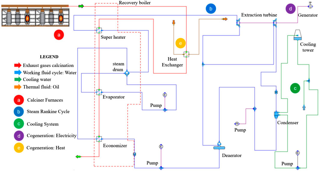
Figure 6. Modeling of Configuration 2.
The process begins with exhaust gases (a) transferring heat to the thermal oil (e) in a heat exchanger. The gases then enter the heat recovery boiler, undergoing heat exchange processes before being exhausted at the economizer outlet. The generated superheated steam is directed to the Rankine cycle turbine (b), where it expands and generates electricity (d). A portion of the steam is extracted, and unlike Configuration 1, the extracted steam from the high-pressure turbine is routed to the deaerator to preheat and mix with the water from the condenser. After expansion in the turbine, the two-phase fluid flows to the condenser, with the cooling tower (c) assisting in heat dissipation. In the deaerator, the water temperature is increased using superheated steam from the high-pressure turbine, removing dissolved gases and improving fluid quality. The treated water is pumped back to the heat recovery boiler, restarting the cycle.
For this configuration, the flue gases discharged from the chimneys (1.36 kg/s at 1.1 bar and 800 °C) first exchange heat to preheat the thermal oil, leaving the heat exchanger at 1.09 bar and 769.01 °C. They are then directed to the HRSG, from which they exit to the atmosphere at 1.06 bar and 190.64 °C. At the inlet of the HT, 0.4695 kg/s of steam enters at 92 bar and 506.42 °C. An extraction flow of 0.1051 kg/s is directed to the deaerator at 10 bar and 227.03 °C. In the LT, 0.3644 kg/s of steam (at 10 bar and 227.03 °C) expands to 0.06 bar and 36.16 °C before entering the condenser.
It is worth noting that, in practice, certain gases may require flaring or proper treatment for safety and environmental reasons, as some gases can be toxic, flammable, and contribute to climate change—such as CO and CH4 present in the exhaust gases of Configurations 1 and 2. However, in this study, these two scenarios were used solely to illustrate the energy potential that is lost when the chemical content of the gases is not utilized.
2.5.4 Configuration 3
In addition to their thermal potential, the exhaust gases possess chemical potential that has not yet been utilized in Configurations 1 and 2. To release this energy and maximize the overall reuse of exhaust gases, Configuration 3 (Figure 7) incorporates a controlled combustion process. Similar to Configuration 1, its main difference lies in the combustion of exhaust gases in the combustion chamber (b) before their integration into the steam thermodynamic cycle. The resulting energy products from combustion are then utilized in the steam system, maintaining the topping cogeneration approach. The process begins with the entry of exhaust gases from the calcination furnaces (a) and atmospheric air into the combustion chamber (b), converting their chemical energy into additional thermal energy. The generated superheated steam is then directed to the conventional Rankine cycle of the topping cogeneration system, following the same path as in Configuration 1.
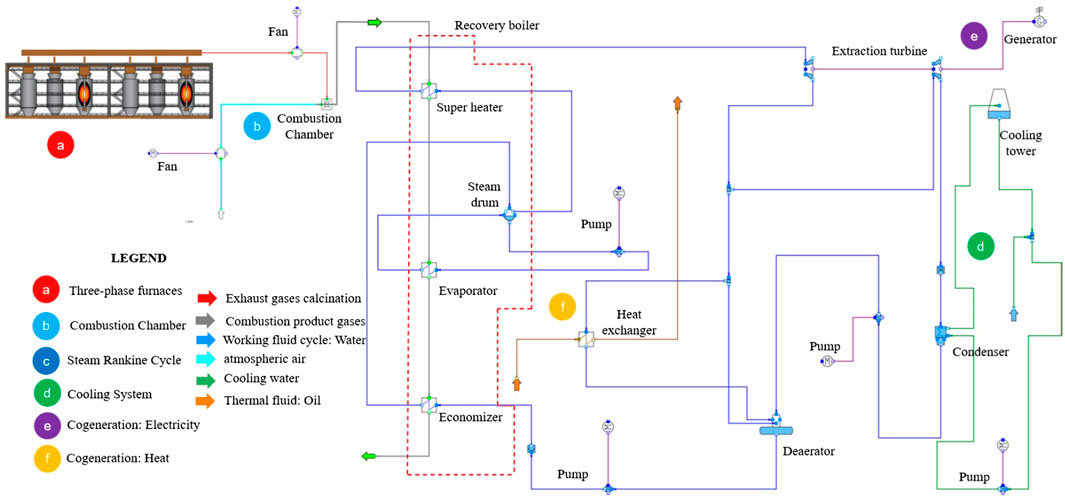
Figure 7. Modeling of Configuration 3.
In the simulations, the flue gases from the chimneys (1.36 kg/s at 1.1 bar and 800 °C) are mixed with ambient air (9.534 kg/s at 1.1 bar and 35.577 °C) in the combustion chamber, producing 10.89 kg/s of combustion gases at 1.1 bar and 800 °C. Under these conditions, the gases enter the HRSG, where they transfer heat and leave at 1.07 bar and 267.69 °C. At the inlet of the high-pressure turbine (HT), 2.636 kg/s of steam (at 92 bar and 598.67 °C) expand to 40 bar and 468.71 °C. From the turbine outlet, 0.03093 kg/s is directed to the thermal oil heating system (entering at 40 bar and 468.71 °C and leaving at 250 °C), 0.7558 kg/s is sent to the deaerator (at 40 bar and 468.71 °C), and 1.85 kg/s expands further in the low-pressure turbine (LT), entering at 40 bar and 468.71 °C and discharging at 0.06 bar and 36.16 °C.
2.5.5 Configuration 4
Similar to Configuration 3, the fourth configuration integrates the thermodynamic characteristics of the bottoming cogeneration system from Configuration 2 with the energy utilization of combustible compounds through the combustion system of Configuration 3. Figure 8 illustrates the system of Configuration 4. The gases generated from combustion (b) are directed to the heat exchanger, where they transfer their thermal energy to the thermal oil (f). After this sensible heat exchange with the oil, the resulting combustion gases proceed to the heat recovery boiler.
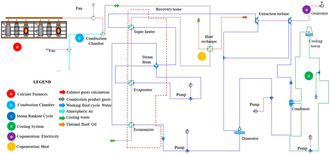
Figure 8. Modeling of Configuration 4.
In the simulations, the combustion chamber operates with the same conditions as in Configuration 3. The resulting gases are directed to the thermal oil heat exchanger, exiting at 1.09 bar and 794.67 °C before entering the HRSG, from which they are discharged into the atmosphere at 1.06 bar and 183.18 °C. At the HT inlet, 2.893 kg/s of steam (at 92 bar and 506.42 °C) expand to 10 bar and 227.03 °C. Of this flow, 0.6475 kg/s is extracted for the deaerator, while the remaining 2.246 kg/s expand further in the LT to 0.06 bar and 36.16 °C.
In all configurations, the thermal oil is heated from 50 °C to 300 °C. In Configurations 1 and 3, where the heat exchanger for this heating process is integrated into the steam cycle, steam is extracted at 40 bar and 468 °C and exits the heat exchanger at 250 °C after heating the oil. In Configurations 2 and 4, the heat exchanger for heating the oil is external to the steam cycle. In Configuration 2, the exhaust gases leave the stack at 800 °C and exit the heat exchanger at 769 °C. In Configuration 4, the gases also leave at 800 °C but exit the heat exchanger at 794 °C, owing to the combustion chamber operation with a large excess of air.
Table 2 summarizes the data employed in the simulations of the four configurations, where HRSG denotes the heat recovery steam generator, HT the high-pressure steam turbine, and LT the low-pressure steam turbine.
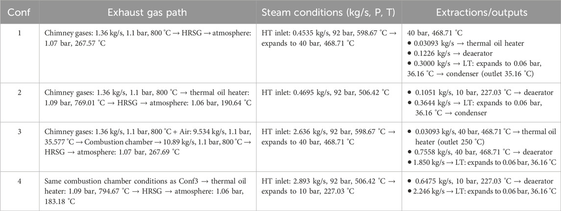
Table 2. Operating parameters for the four cogeneration system configurations.
3 Results and discussions
The results section is divided into the thermodynamic analyses of energy and exergy balances and the environmental analysis based on avoided emissions.
3.1 Energy and exergy balance
Table 3 presents the exergy balance obtained through simulations, while Figure 9a,b show the energy and exergy efficiencies of the steam power cycle and the cogeneration system as a whole, respectively. All the parameters are determined using the equations presented in section 2.3.
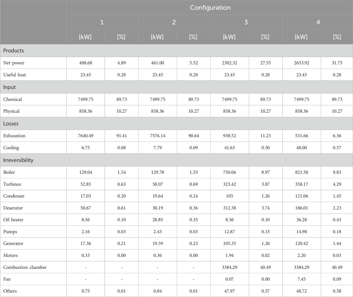
Table 3. Exergy balance of the four configurations.
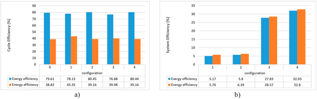
Figure 9. Energy and exergy efficiencies of: (a) the steam power cycle; (b) the cogeneration system.
3.1.1 Configuration 1
Regarding Table 3 and Figure 9b), the low exergy efficiency in Configuration 1 (5.17%) is justified by the lack of utilization of the chemical component of the exhaust gases. This exergy analysis reveals that the majority of exergy losses occur in the recovery boiler exhaust (91.41%), primarily due to the 7499.75 kW of unutilized chemical exergy. This result underscores the importance of integrating a combustion chamber to optimize furnace gas utilization and minimize energy and exergy losses.
3.1.2 Configuration 2
Configuration 2 exhibits low exergy efficiency for the same reason as Configuration 1. In the exergy analysis of losses and irreversibilities, it is observed that only 5.80% of the total inputs are converted into exergy products, i.e., 94.20% of the inputs are lost due to irreversibilities and losses. Once again, this finding justifies the implementation of combustion technologies to enhance resource utilization.
3.1.3 Configuration 3
Like Configuration 1, Configuration 3 represents a topping-cycle cogeneration system. However, it incorporates the combustion of exhaust gases, allowing for a more complete and efficient utilization of the chemical energy contained in these gases. As a result, an increase in the system’s exergy efficiency is observed. In Configuration 3, the exhaust gas flow rate from the combustion chamber is approximately eight times higher than in the first two configurations. This design choice prevents excessively high gas temperatures at the outlet of the combustion chamber, ensuring compliance with the technological limits of subsequent system components. To achieve this, combustion was simulated with a large excess of air, thereby limiting the temperature of the combustion products at the inlet of the recovery boiler.
Further regarding Configuration 3 (Table 3), in the exergy analysis of irreversibilities and losses, it is observed that 27.83% of the total inputs are converted into exergy products. This implies that 72.17% of the inputs are not utilized. Within this total, only 11.73% corresponds to exergy losses associated with the recovery boiler exhaust and condenser cooling.
From an exergy perspective, when comparing Configuration 3 to Configuration 1 (both topping cogeneration systems), Configuration 1 exhibits over 90% exergy losses, whereas in Configuration 3, losses do not exceed 12%. This reduction is primarily attributed to the addition of the combustion chamber, aimed at harnessing the chemical energy of the gases. However, while exhaust gas losses were reduced, there was an increase of nearly 60% in the system’s internal irreversibilities. Of this total, 40.49% of the internal irreversibilities occurred within the combustion chamber. This arises from the equipment’s metallurgical limitations, requiring an excess of air and increasing irreversibility within the chamber.
3.1.4 Configuration 4
The fourth configuration (bottoming-cycle), includes a heat exchanger outside the thermodynamic cycle and also features a combustion chamber. The exergy efficiency is 32.03%. The increase in efficiency is justified by the absence of a heat exchanger within the power cycle, which is now solely responsible for producing electricity. Additionally, this result is attributed to the use of the combustion chamber. In the analysis of exergy losses and irreversibilities, it is observed that 32.03% of the total inputs are converted into exergy products. This indicates that 67.97% of the inputs are lost due to irreversibilities and losses. Of this total, only 6.94% corresponds to exergy losses associated with exhaust and cooling. The reduction in losses from over 90% to approximately 7% confirms that the utilization of the combustion chamber plays a crucial role in harnessing these gases. However, internal irreversibilities total more than 60%, due to the same reason observed in the third configuration, where the combustion chamber is the main component responsible for the highest system losses.
3.1.5 Comparisons
The energy and exergy efficiencies of the four configurations, as well as the baseline case, for the power cycles were compared, as shown in Figure 9a). It is observed that the second-law efficiency was higher than the first-law efficiency. This occurs because exergy efficiency accounts not only for the quantity of energy but also for its quality. In all five cases analyzed, the exergy fractions of the added heat were lower compared to the added energy. Consequently, when calculating the ratio outputs/inputs, the efficiency of the cycle increased in the exergy-based calculations.
When comparing the efficiencies of the four cycles with the results of Configuration 0, it is noted that the obtained values are quite similar. Thus, the efficiencies of Configurations 1 to 4 fall within the expected range. This occurs because the cycle efficiency depends on the thermodynamic mean temperature of heat addition (in the boiler) and the thermodynamic mean temperature of heat rejection (in the condenser), that is, on the temperatures and pressures at the inlets and outlets of these components. Since configuration zero was used as the reference, these parameters were kept the same in the proposed configurations (1–4). This explains the similar results shown in Figure 9a).
When analyzing the system as a whole, the cogeneration system efficiency (Figure 9b) results considered only Configurations 1 to 4, as additional information, such as the exergy of the useful heat from the district heating system, was not available for Configuration 0. Figure 9b) shows higher efficiencies for Configurations 3 and 4, which are attributed to the complete utilization of the energy from the exhaust gases. This occurs because combustion not only facilitates the chemical treatment of the gases but also enables efficient recovery of residual thermal energy. This process maximizes the use of available resources and enhances the system’s energy performance. Additionally, the improved integration between thermal and chemical processes contributes to overall efficiency by reducing waste and optimizing resource utilization.
In the comparison of cogeneration systems (Figure 9b), it is observed that Configuration 1 (topping) exhibits lower energy and exergy efficiencies compared to Configuration 2 (bottoming). A similar trend is observed between Configurations 3 (topping) and 4 (bottoming). This occurs because, in topping cycle systems, the heating of the thermal oil is integrated into the cycle, requiring the extraction of a larger amount of steam from the high-pressure turbine for the heat exchanger. Consequently, less steam is available for expansion in the low-pressure turbine, reducing electrical power generation. In contrast, in bottoming cycle systems, the heat exchanger is external to the cycle, allowing the thermal oil to be heated without the need for significant steam extraction from the turbines.
3.1.6 Grassmann diagram
To improve the visualization of the data in Table 3, facilitate the interpretation of the graphs in Figure 9, and illustrate the distribution and conversion of exergetic resources (chemical and physical) into products, losses, and irreversibilities, Figure 10 presents the Grassmann diagrams (usually referred to as exergy diagrams) for each configuration. These diagrams facilitate the visualization of the energy conversion process associated with the systems of each configuration, and all values shown in Figure 10 are expressed in kW.
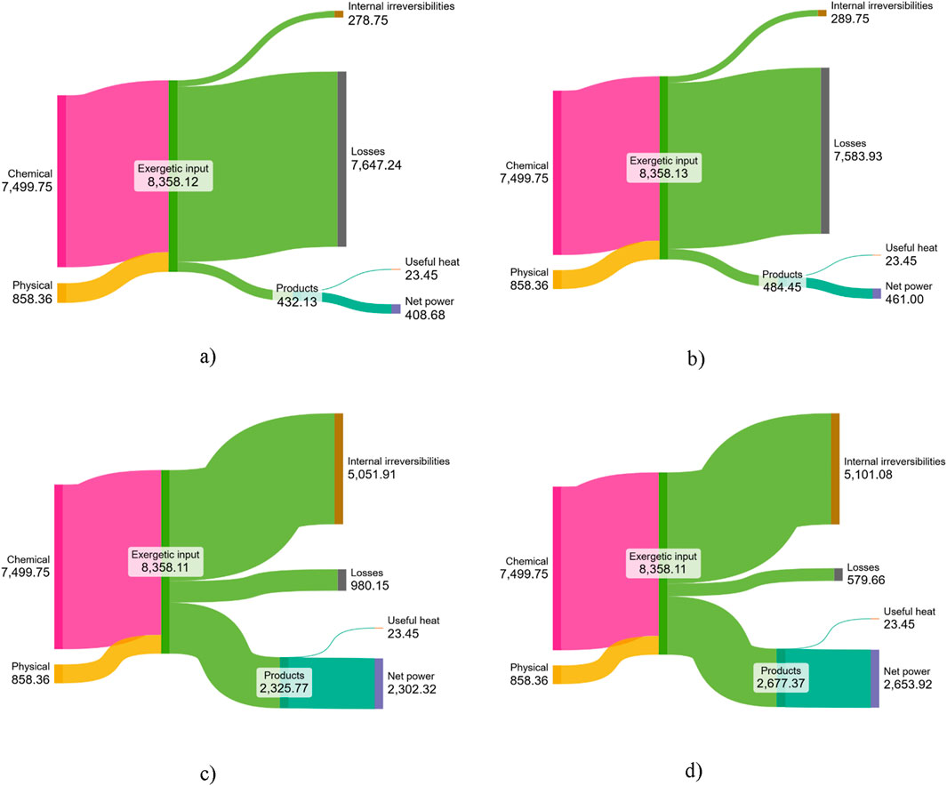
Figure 10. Grassmann diagram for each configuration [kW]. (a) Configuration 1. (b) Configuration 2. (c) Configuration 3. (d) Configuration 4.
The exergetic input, chemical and physical, is identical (8358.1 kW) across all configurations in Figure 10. In Configurations 1 and 2 (Figures 10a,b), only a small fraction of these inputs is converted into final products (useful heat and net power), while most is lost (7647.24 kW and 7583.93 kW for Configurations 1 and 2, respectively). This results from the absence of a combustion chamber to exploit the chemical energy of the exhaust gases, leading to low energy and exergy efficiencies, as shown in Figure 9.
In Configurations 3 and 4 (Figures 10c,d), combustion prior to the thermodynamic cycle enables greater utilization of the chemical potential of the gases, substantially increasing electricity generation to 2302.32 kW and 2653.92 kW in Configurations 3 and 4, respectively. Efficiencies rise to around 30% (Figure 9), with losses reduced compared to Configurations 1 and 2. However, internal irreversibilities, particularly in the combustion chamber, increase due to the requirement for excess air. This excess is employed to ensure that the temperature of the exhaust gases does not exceed the metallurgical limits of the material.
This study was conducted based on steam cycle technology to demonstrate the potential for recovering the thermal (1.63 MW) and chemical (6.67 MW) energy contained in the flue gases, using the work of Rohde et al. (2020) —which investigated a similar system applied to a carbo-chemical plant within the same industrial group as the facility analyzed here—as a reference. The results indicated the possibility of generating 2.65 MW of electricity with an efficiency slightly above 30%. However, the detailed first and second law analysis carried out in the present work provided valuable insights into an alternative technological approach, consisting of a sequential and alternating combination of an Organic Rankine Cycle (ORC) for thermal energy recovery and an Internal Combustion Engine (ICE) for chemical energy recovery. For thermal sources at approximately 800 °C, an ORC operating with toluene can reach efficiencies of around 25% (Morawski et al., 2021), which would yield up to 0.41 MW of electricity. An ICE with residual heat recovery (ICE–ORC configuration) can achieve nearly 50% efficiency (de Araújo et al., 2022), generating up to 3.34 MW of electrical power. Therefore, this combined route (ORC–ICE–ORC) could generate up to 3.75 MW of electricity, representing more than a 40% increase compared with the cogeneration performance of the conventional steam cycle.
3.2 Avoided emissions
For this analysis, the emission factors shown in Figure 3 were employed. Three different scenarios were considered: (a) the highest emission factor in recent years, 135.5 kg CO2/MWh in 2014; (b) the lowest emission factor, 29.2 kg CO2/MWh in 2011; and (c) a median emission factor of 74 kg CO2/MWh in 2018. The avoided emissions, expressed as the amount of CO2 (tons/year) for each configuration and for each of the three emission factor scenarios, are shown in Figure 11.
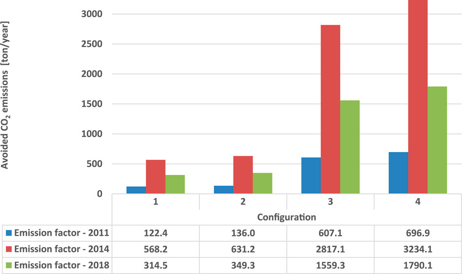
Figure 11. Avoided CO2 emissions due to electricity generation.
Considering that the values presented in Figure 11 represent the amount of CO2 that would be avoided by utilizing the electricity generated by the cogeneration system to meet the internal demands of the plant, it is evident that, across the three scenarios of emission factor analyzed, Configurations 3 and 4 resulted in the greatest emission reductions when compared to Configurations 1 and 2. This is due to the fact that Configurations 3 and 4 maximize the utilization of the thermal and chemical potential of the exhaust gases by combusting them, which leads to higher efficiency and electricity generation within the system. As a result, the CO2 emissions of these configurations was significantly lower than that of the others. This result corroborates the well-established notion that the implementation of cogeneration systems, such as the one examined in this study, not only improves the energy and exergy efficiency of the system but also provides significant environmental benefits.
Furthermore, considering the most optimistic scenario with a low emission factor of 29.2 kg CO2/MWh for the year 2011, the reductions in emissions reach a maximum of 696.9 tons/year in Configuration 4. Nevertheless, in a scenario with a high emission factor, such as that of 2014, when it was 135.5 kg/MWh, emission reductions can reach considerable values of 2817.1 and 3234.1 tons/year in Configurations 3 and 4, respectively.
Moreover, from the perspective of thermal pollution, an analysis of the second column (“Exhaust gas path”) of Table 2 reveals a 66% reduction in the exhaust gas temperatures for Configurations 1 and 3, and a 77% reduction for Configurations 2 and 4, relative to the initial 800 °C at the stack outlet.
4 Conclusion
This study investigated the potential for energy recovery from exhaust gases in a Brazilian carbo-chemical plant by analyzing various steam cogeneration system configurations. Thermodynamic simulations and analyses, conducted using the IPSEpro 8.0 software, demonstrated that improvements in both energy and exergy efficiencies could be achieved by harnessing the thermal and chemical energy contained in these gases. The findings indicated that while the initial configurations (1 and 2) exhibited lower efficiencies due to unutilized chemical exergy, the incorporation of a combustion chamber (Configurations 3 and 4) significantly enhanced energy recovery, achieving energy and exergy efficiencies of up to 32.8% and 32.03%, respectively, in the final configuration.
Furthermore, Configuration 4, which employs a bottoming-type cogeneration cycle, utilizes the available energy resources more effectively, providing an electric power output of up to 2.65 MW. Additionally, the study highlighted that integrating combustion not only improved the overall system efficiency but also yielded environmental benefits by mitigating thermal and chemical pollution. The quantification of avoided CO2 emissions further substantiated the environmental advantages associated with implementing cogeneration for energy recovery. In this analysis, the configurations incorporating a combustion chamber (3 and 4) also demonstrated the highest emission reduction potential, preventing the release of CO2 into the atmosphere. Even in an optimistic scenario, where the emission factor is low, reductions of 607.1–696.9 tons of CO2 per year can be achieved, whereas in the most pessimistic scenario, with a high emission factor, the reductions reach 2817.1–3234.1 tons of CO2 per year. Regarding thermal pollution, configuration 4 reduces the temperature of the gases released into the atmosphere by 77%.
Configurations 3 and 4, which employ a combustion chamber to exploit the full energy potential of the flue gases, yield the best results both in terms of energy conversion and environmental performance regarding avoided emissions.
Nevertheless, further research is required to evaluate additional factors, particularly the economic feasibility of deploying these cogeneration systems on an industrial scale. A comprehensive cost-benefit analysis should be undertaken to assess capital investment needs, operational expenditures, and potential financial returns. Moreover, if the project is to be considered for inclusion in a carbon market, an assessment of prospective revenues from carbon credit trading, alongside an analysis of the regulatory framework governing emission reductions, is essential. These considerations will be crucial in facilitating the practical implementation and long-term financial viability of energy recovery strategies within the carbo-chemical industry. Furthermore, the exergy balance analysis identified the locations of the greatest losses and the sources of irreversibilities. Based on these findings, strategies can be explored to mitigate these losses and, consequently, enhance system efficiency.
Finally, the results of this study, which demonstrated the potential energy that can be recovered from industrial exhaust gases through steam-based cogeneration systems, provide the insight that an optimized technological route may achieve even better outcomes. For instance, a combined and sequential ORC–ICE–ORC configuration could reach efficiencies of up to 50% and generate 40% more electricity. Technological routes of this kind may be investigated as a complementary extension of the present work.
Data availability statement
The raw data supporting the conclusions of this article will be made available by the author, without undue reservation.
Author contributions
AQ: Data curation, Formal Analysis, Investigation, Methodology, Software, Writing – review and editing. BS: Formal Analysis, Investigation, Methodology, Writing – review and editing. FF: Data curation, Formal Analysis, Methodology, Software, Visualization, Writing – original draft, Writing – review and editing. PF: Formal Analysis, Methodology, Visualization, Writing – original draft, Writing – review and editing. JS: Conceptualization, Formal Analysis, Project administration, Supervision, Validation, Writing – review and editing.
Funding
The author(s) declare that financial support was received for the research and/or publication of this article. FF thanks the Espírito Santo Research and Innovation Support Foundation (FAPES). PF thanks the Espírito Santo Research and Innovation Support Foundation (FAPES) – Process: 2024-GXP3C; T.O: 090/2025 and the IFES campus Cariacica. JS thanks the National Council for Scientific and Technological Development (CNPq, Brazil).
Conflict of interest
The authors declare that the research was conducted in the absence of any commercial or financial relationships that could be construed as a potential conflict of interest.
Generative AI statement
The author(s) declare that no Generative AI was used in the creation of this manuscript.
Any alternative text (alt text) provided alongside figures in this article has been generated by Frontiers with the support of artificial intelligence and reasonable efforts have been made to ensure accuracy, including review by the authors wherever possible. If you identify any issues, please contact us.
Publisher’s note
All claims expressed in this article are solely those of the authors and do not necessarily represent those of their affiliated organizations, or those of the publisher, the editors and the reviewers. Any product that may be evaluated in this article, or claim that may be made by its manufacturer, is not guaranteed or endorsed by the publisher.
References
Ahmadi, G. R., and Toghraie, D. (2016). Energy and exergy analysis of montazeri steam power plant in Iran. Renew. Sustain. Energy Rev. 56, 454–463. doi:10.1016/j.rser.2015.11.074
Brückner, S., Liu, S., Miró, L., Radspieler, M., Cabeza, L. F., and Lävemann, E. (2015). Industrial waste heat recovery technologies: an economic analysis of heat transformation technologies. Appl. Energy 151, 157–167. doi:10.1016/j.apenergy.2015.01.147
Çengel, Y., Boles, M., and Kanoglu, M. (2023). Thermodynamics: an engineering approach. 10th ed. McGraw-Hill. Available online at: https://www.mheducation.com/highered/product/thermodynamics-engineering-approach-cengel-boles/M9781266664489.html.
de Araújo, L. R., Morawski, A. P., Barone, M. A., Rocha, H. R. O., Donatelli, J. L. M., and Santos, J. J. C. S. (2022). Response surface methods based in artificial intelligence for superstructure thermoeconomic optimization of waste heat recovery systems in a large internal combustion engine. Energy Convers. Manag. 271, 116275. doi:10.1016/j.enconman.2022.116275
Feidt, M., and Costea, M. (2012). Energy and exergy analysis and optimization of combined heat and power systems. Comparison of various systems. Energies 5 (9), 3701–3722. doi:10.3390/en5093701
Frangopoulos, C. A. (2017). Cogeneration - Technologies, optimisation and implementation. London, United Kingdom: The Institution of Engineering and Technology.
Gandt, K., Meier, T., Echterhof, T., and Pfeifer, H. (2016). Heat recovery from EAF off-gas for steam generation: analytical exergy study of a sample EAF batch. Ironmak. and Steelmak. 43 (8), 581–587. doi:10.1080/03019233.2016.1155812
Gasik, M. M., Gasik, M. I., Urazlina, O. Y., and Kutuzov, S. V. (2010). “Modelling and optimisation of anthracite treatment in an electrocalcinator,” in Proceedings of the twelfth international ferroalloys congress sustainable future.
Governo do Estado do Espírito, S. (2023). Espírito santo’s decarbonization and GHG emissions neutralization plan - Executive summary. Available online at: https://planodescarbonizacao.es.gov.br/Media/PlanoDescarbonizacao/Documentos/Executive%20Summary.pdf.
Iglesias Garcia, S., Ferreiro Garcia, R., Carbia Carril, J., and Iglesias Garcia, D. (2018). A review of thermodynamic cycles used in low temperature recovery systems over the last two years. Renew. Sustain. Energy Rev. 81, 760–767. doi:10.1016/j.rser.2017.08.049
International Energy Agency (IEA) (2021). Snapshot of global PV markets 2021. Available online at: https://iea-pvps.org/snapshot-reports/snapshot-2021/.
Lemos, L. de S., Goulart, P. de M. A., Leão Jr, R. G., Carpio, R. C., and Fernandes, M. T. (2021). “Exergy analysis of the electricity generation process in the reuse of blast furnace gases in a steelmaking company,” in Proceedings of the 26th ABCM International Congress of Mechanical Engineering (COBEM 2021).
Ministério da Ciência, T. e. I. (2024). Sistema de Registro Nacional de Emissões (SIRENE). Available online at: https://www.gov.br/mcti/pt-br/acompanhe-o-mcti/sirene.
Morawski, A. P., de Araújo, L. R., Schiaffino, M. S., de Oliveira, R. C., Chun, A., Ribeiro, L. C., et al. (2021). On the suitable superstructure thermoeconomic optimization of a waste heat recovery system for a Brazilian diesel engine power plant. Energy Convers. Manag. 234, 113947. doi:10.1016/j.enconman.2021.113947
Ng, C., Tam, I. C. K., and Wu, D. (2020). Thermo-economic performance of an organic rankine cycle system recovering waste heat onboard an offshore service vessel. J. Mar. Sci. Eng. 8 (5), 351. doi:10.3390/jmse8050351
Nikafshan Rad, H., Ghasemi, A., and Marefati, M. (2024). Cost and environmental analysis and optimization of a new and green three-level waste heat recovery-based cogeneration cycle: a comparative study. Heliyon 10 (7), e29087. doi:10.1016/j.heliyon.2024.e29087
Oyedepo, S. O., and Fakeye, B. A. (2021). Waste heat recovery technologies: pathway to sustainable energy development. J. Therm. Eng. 7 (1), 324–348. doi:10.18186/thermal.850796
Pawlenka, T., Juránek, M., Klaus, P., Beseda, M., Buráň, M., Suchánek, M., et al. (2023). Compact automatic controlled internal combustion engine cogeneration system based on natural gas with waste heat recovery from the combustion process. Therm. Sci. Eng. Prog. 44, 102042. doi:10.1016/j.tsep.2023.102042
Prestipino, M., Piccolo, A., Vilela, C. M., and Galvagno, A. (2025). Cogeneration processes based on giant reed gasification combined with ORC and district heating for heat recovery: comparative energy and exergy analysis. Renew. Energy 238, 121944. doi:10.1016/j.renene.2024.121944
Rohde, D., Andresen, T., Zotica, C., and Wilpert, P. (2020). “Energy recovery from furnace off-gas: analysis of an integrated energy recovery system by means of dynamic simulation,” in Proceedings of the Rankine 2020 Conference - Advances in Cooling, Heating and Power Generation.
Rohde, D., Beck, A., Wilpert, P., Dusek, S., Windfeldt, M. K., and Andersson, L. E. (2022). Thermal energy storage for increased waste heat recovery at a silicon production plant in Norway. Appl. Therm. Eng. 215, 118909. doi:10.1016/j.applthermaleng.2022.118909
Shamet, O., Ahmed, R., and Nasreldin Abdalla, K. (2021). Energy and exergy analysis of a steam power plant in Sudan. Afr. J. Eng. and Technol. 1 (1). doi:10.47959/AJET.2021.1.1.4
Silva, D. L. I. (2016). Recuperação de Calor Residual de Baixa Qualidade em Usinas Termelétricas de Ciclo Combinado. portuguese: Universidade Federal de Itajubá UNIFEI. Master dissertation.
Simtechnology (2024). IPSEpro. Available online at: https://simtechnology.com/ipsepro/process-simulation-and-heat-balance-software.
Tumidajski, P. J., Schumacher, A. S., Perron, S., Gu, P., and Beaudoin, J. J. (1996). On the relationship between porosity and electrical resistivity in cementitious systems. Cem. Concr. Res. 26 (4), 539–544. doi:10.1016/0008-8846(96)00017-8
World Steel Association (2024). World steel in figures. Available online at: https://worldsteel.org/data/world-steel-in-figures-2024/.
Zhang, Y., Xiong, N., Ge, Z., Zhang, Y., Hao, J., and Yang, Z. (2020). A novel Cascade heating system for waste heat recovery in the combined heat and power plant integrating with the steam jet pump. Appl. Energy 278, 115690. doi:10.1016/j.apenergy.2020.115690
Glossary
APP Advanced Power Plant
CSP Concentrated Solar Power
CHP Combined Heat and Power
E Exergy (kW)
ECA Electrically Calcinated Anthracite
GHG Greenhouse gas
h Specific enthalpy (kJ/kg)
HRSG Heat recovery steam generator
HT High-pressure steam turbine
ICE Internal combustion engine
IEA International Energy Agency
LHV Lower heating value (kJ/kg)
LT Low-pressure steam turbine
MM Molar mass (kg/mol)
ORC Organic Rankine Cycle
p Pressure (bar)
Q Heat (kW)
R Universal gas constant kJ/(kmol·K)
s Specific entropy (kJ/kg.K)
T Temperature (°C)
W Power (kW)
y Mole fraction
Greek letters
Δ Variation
η Energy efficiency
ε Exergy efficiency
Subscript
0 Environment
ad Added
ch Chemical
F Fuel
i Indexes
N Net
u Useful
Superscript
sch Standard chemical exergy
Keywords: energy recovery, waste energy, carbo-chemical, exergy analysis, decarbonization, avoided emissions
Citation: Quintão AL, Sant’ana BBP, Fonseca FM, de Faria PR and Santos JJCS (2025) Simulation and thermodynamic evaluation of steam cogeneration system configurations for energy recovery from exhaust gases of a carbo-chemical industry. Front. Chem. Eng. 7:1695423. doi: 10.3389/fceng.2025.1695423
Received: 29 August 2025; Accepted: 06 October 2025;
Published: 27 October 2025.
Edited by:
Pablo Silva Ortiz, Universidad Industrial de Santander, ColombiaReviewed by:
York Castillo Santiago, Fluminense Federal University, BrazilJuan Pablo Flórez Mera, Universidad Industrial de Santander, Colombia
Copyright © 2025 Quintão, Sant’ana, Fonseca, de Faria and Santos. This is an open-access article distributed under the terms of the Creative Commons Attribution License (CC BY). The use, distribution or reproduction in other forums is permitted, provided the original author(s) and the copyright owner(s) are credited and that the original publication in this journal is cited, in accordance with accepted academic practice. No use, distribution or reproduction is permitted which does not comply with these terms.
*Correspondence: José Joaquim Conceição Soares Santos, am9zZS5qLnNhbnRvc0B1ZmVzLmJy