 Kai Janning1*
 Abdalsalam Housin1Christopher Schulte2
 Frederik Erkens1Luca Frenken1
 Laura Herbst1
 Bastian Nießing1
 Robert H. Schmitt1,3
- 1Department of Bioadaptive Production, Fraunhofer Institute for Production Technology IPT, Aachen, Germany
- 2Institute of Automatic Control (IRT), RWTH Aachen University, Aachen, Germany
- 3Laboratory for Machine Tools and Production Engineering (WZL), Intelligence in Quality Sensing, RWTH Aachen University, Aachen, Germany
Introduction: This work presents an approach to collision avoidance in multi-agent systems (MAS) by integrating Conflict-Based Search (CBS) with Model Predictive Control (MPC), referred to as Conflict-Based Model Predictive Control (CB-MPC).
Methods: The proposed method leverages the conflict-avoidance strengths of CBS to generate collision-free paths, which are then refined into dynamic reference trajectories using a minimum jerk trajectory optimizer and then used inside a MPC to follow the trajectories and to avoid collisions. This integration ensures real-time trajectory execution, preventing collisions and adapting to online changes. The approach is evaluated using a magnetic planar drive system for realistic multi-agent scenarios, demonstrating enhanced real-time responsiveness and adaptability. The focus is on the development of a motion planning algorithm and its validation in dynamic environments, which are becoming increasingly relevant in modern adaptive production sites.
Results: On the MAS demonstrator with four active agents, ten different scenarios were created with varying degrees of complexity in terms of route planning. In addition, external disturbances that hinder the execution of the paths were simulated. All calculation and solution times were recorded and discussed. The result show that all scenarios could be successfully solved and executed., and the CB-MPC is therefore suitable for motion planning on the presented MAS demonstrator.
Discussion: The results show, that the CB-MPC is suitable for motion planning on the presented MAS demonstrator. The greatest limitation of the approach lies in scalability with regard to increasing the number of agents.
1 Introduction
Traditional assembly lines, forming the backbone of conventional manufacturing, are inherently linear and sequential, limiting flexibility and adaptability – crucial attributes needed to meet the dynamic demands of modern production. Recent advancements in Multi-agent Systems (MAS) propose a paradigm shift towards adaptive and decoupled manufacturing processes, heralding the era of smart manufacturing (Brecher, 2012; Göppert et al., 2018; Hu et al., 2011). MAS enhance manufacturing systems by enabling autonomous agents to dynamically transport components, optimizing production flow, and enabling customization. This flexibility can result in increased system productivity by reducing bottlenecks and idle times (Komesker et al., 2022). Figure 1 illustrates the contrast between traditional conveyor belts and advanced planar drive systems, highlighting the potential of MAS and advanced control algorithms (Brecher et al., 2017).
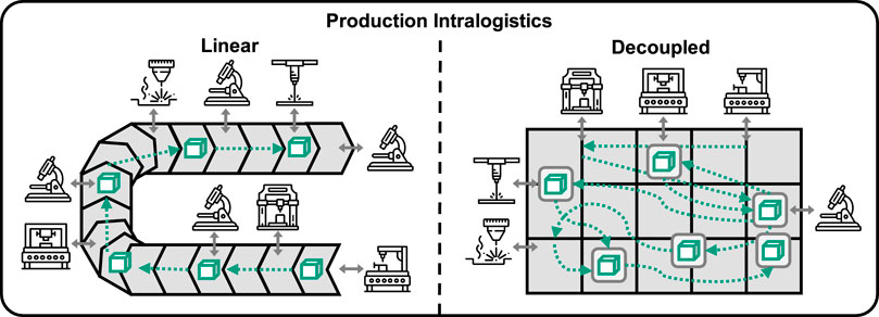
Figure 1. Schematic comparison between linear and decoupled production intrologistics systems.
However, managing multiple autonomous agents to avoid collisions remains a significant challenge. Multi-Agent Path Finding (MAPF) is crucial in applications such as automated warehousing and production intralogistics, where numerous agents handle transportation tasks. Although MAPF algorithms can generate collision-free paths, they often lack real-time monitoring and adaptability to dynamic changes, limiting their effectiveness. In dynamic environments such as on colaborative production sites, adressing these limitations are vital for enhancing the utility of MAS (Komesker et al., 2022).
An exemplary application of MAS is the integration of a magnetic planar drive system for intralogistic processes. A magnetic planar drive allows frictionless product transport and can facilitate flexible, non-linear process chains (Janning et al., 2025; Wang et al., 2024). Planar drive systems consist of a stationary plane (stator) consisting of multiple modular tiles and movable transport units (movers). The stator’s conductor coils generate electromagnetic fields interacting with the movers’ permanent magnets, enabling precise multi-directional movement. This technology suits cleanroom production and modern Industry 4.0 applications, allowing for adaptable path changes and high-precision transport (Janning et al., 2025; Wang et al., 2024). The flexibility and precision of planar drives make them a suitable testbed for evaluating the proposed motion planning algorithm. Figure 2A shows a self-developed MAS demonstrator, which consists of a Beckhoff Automation XPlanar system with 3 × 4 stator tiles and four movers, each embodying an agent, visualized in Figure 2B. The system is controlled via a Beckhoff PLC with the TwinCAT environment. By adding stations for tasks such as pipetting liquids and visual inspections, adaptive processes can be implemented that require flexible modifications of the process chains and thus of the mover paths.
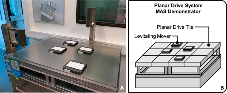
Figure 2. Presentation of a multi-agent system demonstrator based on a magnetic planar drive system with four levitating movers acting as independent transport units (A) and a schematic representation of the system showing the tile-based modular design (B).
The MAPF required for this purpose is a computational problem that entails planning conflict-free paths for multiple agents. Each agent aims to reach a designated target while avoiding collisions with both static obstacles and other agents. The goal is to minimize either the sum of their travel times, the makespan, or other optimization criteria (Stern et al., 2019; Yu, 2016). The mathematical fundamentals of MAPF problems are extensively described by Stern et al. MAPF solvers are generally divided into optimal and suboptimal algorithms. Suboptimal algorithms are further classified into bounded and unbounded solvers (Gao et al., 2024). In the context of production and logistics, suboptimal solvers are prevalent because finding a solution quickly is often more important than finding an optimal solution through high computational effort (Gao et al., 2024; Liu et al., 2024). However, this study investigates whether optimal solvers can also be designed for practical application with sufficient speed and scalability. A common approach for the optimal solution of MAPF problems is conflict-based search (CBS). CBS is particularly well-suited for small to medium-sized scenarios where optimal paths are needed for a limited amount of agents. However, as the number of conflicts grow exponentially with the number of agents, CBS becomes less efficient for large and complex problems. In such cases, extensions are made to employ Improved CBS (ICBS) to provide faster solutions (Sharon et al., 2015; Stern, 2019).
For the MAS demonstrator an ICBS involves representing the planar drive system as a graph where each tile acts as a vertex, and the distance from the center of one tile to the center of an adjacent tile is represented as an edge. This graph representation (Diestel, 2012) is vital for accurately modeling the movement and interaction of movers on the planar drive system. Moreover, defining and communicating the accessible space in this context, a binary map is used, where “true” indicates an obstacle and “false” signifies a free vertex or location. Thus, ICBS can effectively generate optimal collision-free paths by resolving conflicts, but it is limited on path planning and does not monitor the execution of these paths. Consequently, it cannot guarantee that agents will not collide during execution, especially if an agent malfunctions or encounters difficulties executing its plan, due to interruptions from the environment. Additionally, MAPF typically assumes agents can move freely to any node on the graph without constraints, which is not practical for scenarios where agents have specific motion constraints and dynamics. To address these shortcomings, it is essential to combine pathfinding with motion planning. While Networked Model Predictive Control (Net-MPC) can theoretically integrate path planning, collision avoidance, and trajectory following into a single optimization problem, this approach often falls short in complex and non-linear scenarios (Maciejowski, 2002). Therefore, a hybrid approach is proposed, merging the strengths of CBS and Net-MPC. CBS provides preliminary optimal plans, simplifying the task for a centralized MPC (CMPC) (Albin Rajasingham, 2021). The CMPC then monitors these plans, ensuring collision avoidance and optimal motion execution in real-time. In this work, this integration is referred to as Conflict-Based MPC (CB-MPC) to indicate the operating principle. Therefore, a theoretical framework was developed, the corresponding algorithm was implemented for application on the MAS demonstrator, and its performance was evaluated. The objective of these investigations is to validate the CB-MPC approach as an optimal solver for a real-world MAPF problem and to identify its limitations with regard to scalability.
2 Development of CB-MPC
CMPC unifies path planning properties, collision avoidance, and trajectory following for simple scenarios but struggles in complex environments. Conversely, ICBS excels in computing collision-free paths in intricate scenarios, addressing static conflicts but not dynamic constraints, cycle conflicts, or transition conflicts (Stern, 2019).
Figure 3 (left) illustrates how two movers (M1 and M2) are navigated from their initial position (■) to their target position (x) using CBS. Here, the movers are considered as point masses, so that a collision occurs due to the overlapping physical dimensions of the movers, even if the positions of the two movers p1 and p2 are not identical at any point in time t. If CBS is selected as the path finding algorithm and a MPC is used for the execution of these paths, additional constraints can be considered (Figure 3, right). The algorithm then enables constraint-based motion planning to ensure a collision-free solution to the MAPF problem.
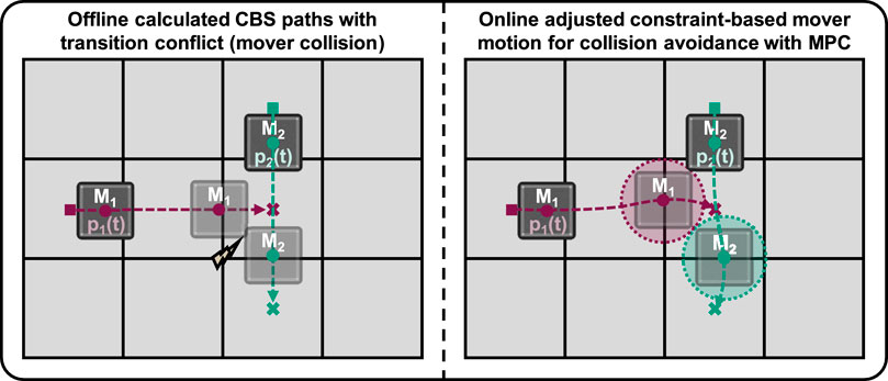
Figure 3. Prevention of transition conflicts in CBS-based mover coordination through MPC.
The CB-MPC framework is a hybrid approach, where ICBS computes conflict-free paths offline, and CMPC executes these paths online in real time. The integration process involves converting ICBS-generated discrete path plans, which may include abrupt transitions and high acceleration variations, into jerk minimized paths via a reference trajectory optimizer. This optimizer smooths the trajectory references, enabling effective execution by CMPC and assuring feasibility for real-world multi-agent coordination applications. The CMPC and ICBS are integrated within a unified CB-MPC framework for MAPF as structurally illustrated in Figure 4.
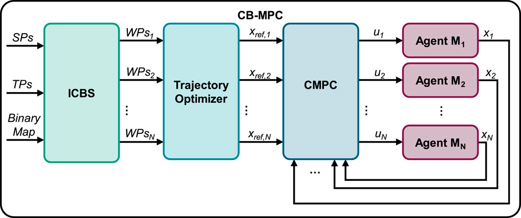
Figure 4. CB-MPC structure.
The ICBS receives the start positions (SPs) and target positions (TPs) of all mover agents involved in the MAPF problem. In addition, a binary map is read out, which indicates whether areas of the grid contain obstacles or are inaccessible. The conflict-free paths determined from this are then converted into waypoints (WPs) for each individual mover. The trajectory optimizer modifies these waypoints as well as the speed and acceleration profiles and returns new reference trajectories (xref,i) for each mover i. These then allow the CMPC to control the state vecors (x) with the control input vectors (u).
The development of the ICBS is explained in Section 2.1, followed by a description of the Trajectory Optimizer in Section 2.2 and the CMPC in Section 2.3. Testing of the entire CB-MPC framework is presented in Section 3.
2.1 Development of a pathfinding algorithm
2.1.1 Conflict-based search
CBS, as a two-level search-based MAPF algorithm, handles collisions by adding constraints at the high level, while at the low level, it computes paths that satisfy these constraints (Sharon et al., 2015). A constraint specifies that a particular agent cannot occupy a specific vertex at a specific time.
At the high level, CBS performs a best-first search on the Conflict Tree (CT) illustrated in Figure 5. Each node in the CT contains a set of constraints that agents must follow as well as the current solution for their paths. The root node starts with no constraints, and each subsequent node adds a new constraint from a detected conflict. The low-level search independently finds paths for each agent while satisfying the constraints imposed by the high-level node. In this work an A* algorithm was chosen due to its optimality, completeness and flexibility (Duchoň et al., 2014). A* is a pathfinding method that evaluates vertices based on their costs to find an optimal path. In this application of mover motion planning, costs are defined as the length of the path from initial to target position of a mover, which is calculated geometrically.
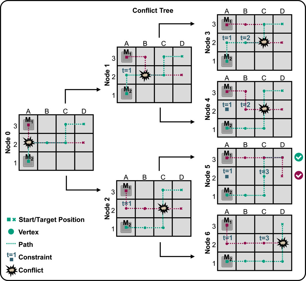
Figure 5. Conflict tree.
Considering a 3 × 4 grid with two mover agents (M1 and M2), initially, an individual, shortest possible path is planned for each agent without any constraints. As shown in Figure 5, the path for M1 is (A3, A2, B2, C2, D2) and the path for M2 is (A1, A2, B2, C2, C3, D3). When these paths are checked, a conflict is found at A2 at time t = 1. The low-level search recomputes individual paths for each agent, considering the new constraint. The CBS high-level search expands the CT with two child nodes with, each forcing one of the agents to avoid A2 at t = 1. In the first node, agent M1 is prohibited from being at A2 at t = 1. The new path for M1 is (A3, B3, B2, C2, D2) and the path for M2 stays the same. In the second node the path for M1 stays the same and a new path for M2 is tested. For both new nodes the paths are again checked for conflicts. If another conflict is found, more nodes are created and more constraints are added. This process is repeated until a solution is found where all agents have collision-free paths and the total cost is minimized. CBS guarantees optimality and completeness by systematically expanding all nodes in the CT until a solution is found or all possibilities are exhausted. Only the possibility of same-cost solutions remain.
2.1.2 CBS improvement
To integrate A* into the CBS framework, modifications were made to allow the algorithm to take constraints as inputs and re-plan paths for multiple constrained agents. Additionally, a specific adjustment enables agents to leave their target positions if the start position was the same as the target, thus avoiding potential deadlocks.
Prior research has introduced numerous techniques to enhance the performance of conflict-based search. These techniques include disjoint splitting (Li et al., 2019b), meta-agent utilization (Sharon et al., 2012), conflict prioritization (Yang and Wooldridge, 2015), conflict bypassing (Boyarski et al., 2015), and the integration of heuristics to speed-up CBS (Li et al., 2019a). In this work, Disjoint Splitting and Dependency Graph heuristics are implemented to accelerate CBS. Figure 6 illustrates the overall structure of the improved CBS for MAPF.
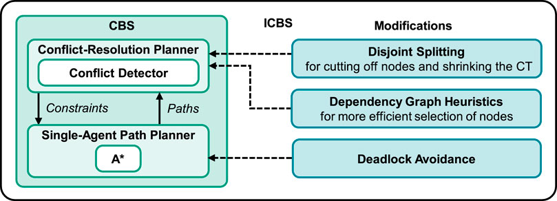
Figure 6. ICBS structure.
Disjoint splitting addresses the inefficiencies of standard CBS splitting by ensuring that subproblems do not share solutions (Li et al., 2019b). This method employs both positive and negative constraints: Positive constraints forcing an agent to be at a specific vertex at a particular time and negative constraints prohibiting an agent from being at a specific vertex at a given time. For every potentially conflict-free plan in a parent CT node, at least one of the two contraints must be satisfied. This approach is called disjoint because both contraints cannot be satisfied simultaneously for a plan. This leads to pruning of nodes, resulting in smaller CTs.
Heuristics are used to enhance the efficiency in selecting possible nodes to be searched for conflicts for expanding the CT (Li et al., 2019a). This research tested three established heuristics: Prioritizing Conflicts (PC), Conflict Graph (CG) and Dependency Graph (DG). The Performance of the heuristics within the ICBS framework was simultatively evaluated using ten random scenarios per agent, with a runtime limit of 5 s. The effectiveness of conflict resolution was tested by comparing the success rates for increasing numbers of agents for each heuristic. In addition, three different grid environments (3 × 4, 4 × 8, 4 × 20) were tested, each with and without the disjoint splitting method. The results shown in Supplementary Material S1 show the highest efficiency using the DG heuristics in every scenario. Due to the superior performance of the dependency graph heuristics combined with disjoint splitting, these are utilized for the implementation of the CB-MPC.
To illustrate the feasibility, Supplementary Material S2, presents the pseudo code of the algorithm used. The improvements to the CBS are based on the approach taken by Felner and Li (Felner et al., 2018; Li et al., 2019a).
2.1.3 Implementation into a programmable logic controller environment
To validate the algorithm in a real-world setting, the Programmable Logic Controller (PLC) environment TwinCAT3 from Beckhoff Automation (Beckhoff Automation GmbH & Co. KG, 2025), which includes Beckhoff’s simulation environment for the XPlanar planar drive system, was utilized. A TwinCAT program was developed to facilitate data exchange between the XPlanar system and the algorithm. This program reads the tile layout, mover dimensions, and positions, transmitting the binary map for the accessible grid, start positions and target positions to the algorithm and receiving way points for collision-free paths in return. These paths are then converted into reference trajectories for execution by the CMPC; compare Figure 4.
As a communication interface between TwinCAT and the algorithm in Python the Automation Device Specification (ADS) protocol (Beckhoff Automation GmbH & Co. KG, 2025) is utilized. Upon initialization, the TwinCAT program sends a handshake signal to the communication program, indicating readiness for data transfer. Following this, the communication program converts the algorithm’s instructions into a format compatible with TwinCAT and transmits them back. This process leverages ADS functions such as read_by_name and write_by_name for efficient data access. Figure 7 partially illustrates the class diagram of the ICBS with PLC communication. Supplementary Material S3 shows the class diagram in detailed form. Additionally, a configuration file in XML format is utilized to define key parameters for the integration, including the AMS Net ID of the PLC, the selection of heuristics for the algorithm, the dimensions of the movers, and the overall layout.
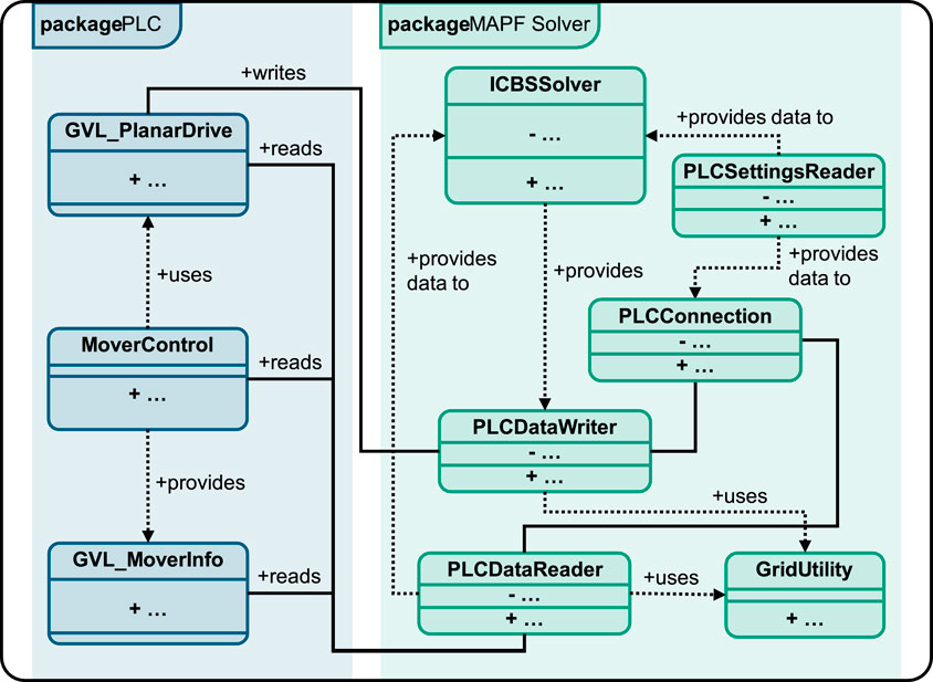
Figure 7. Simplified class diagram showing the communication between ICBS algorithm and PLC.
The GVL_PlanarDrive receives the results of the algorithm in the form of lists with velocities and waypoints of the individual movers, which are written to global variable lists (GVLs). By setting individual trigger GVLs, individual methods of the MoverControl class, such as initializations or the execution of the paths, are activated. In doing so, all current positions of the movers and the obstacle map states are transmitted to the GVL_MoverInfo. The PLCDataReader reads these information and passes them back to the ICBSSolver. The ICBSSolver additionally receives the information of the XML file and the PLC settings from the PLCSettingsReader class. The OPC is then specified with these information and the pathfinding problem is solved. The calculated paths are then passed to the PLCDataWriter, which in turn writes the GVLs of the GVL_PlanarDrive.
Additionally, the ICBS algorithm operates on demand, activated by a user command or a higher-level order. Figure 8 shows the state chart illustrating the ICBS for planning and executing required movements and processes. The ADS and algorithm components are merged and packaged into an executable (.exe) file. Supplementary Material S4 illustrates the ICBS interface, showcasing the algorithm’s real-time execution in a path planning scenario.
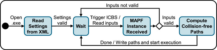
Figure 8. ICBS statechart.
With the start of the path plan execution, the lists with WPs for the individual movers are passed to a trajectory optimizer, whereupon these time-discretized trajectories are executed by the CMPC.
2.2 Reference trajectory optimization
To ensure smooth and dynamically feasible trajectories within the CB-MPC framework, the pre-build Minimum Jerk Trajectory Optimizer, available in MATLAB/Simulink is utilized (The MathWorks, Inc, 2021). This is particularly important for the transportation of delicate items, where smooth trajectories are essential to avoid abrupt motions and high acceleration variations. This optimizer minimizes the jerk, which is the third derivative of position with respect to time (Lozer et al., 2025). The optimization problem can be formulated as minimizing the integral of the squared jerk (Equation 1) over the trajectory duration T:
The calculus of variations is used to determine the function x(t) that minimizes the integral of the squared jerk over the duration of the trajectory. This process ensures that the resulting trajectory is smooth by avoiding abrupt changes in acceleration. This approach shows that the sixth derivative of the position (x) must be zero (Equation 2):
This condition implies that x(t) must be a polynomial of at most fifth order. Thus, a fifth-order polynomial (Equation 3) is chosen to model the position trajectory, ensuring continuity:
Taking the first and second derivatives, the velocity v(t) (Equation 4) and acceleration a(t) (Equation 5) are given by:
The optimizer ensures that the coefficients α0, α1, α2, α3, α4, α5 satisfy the boundary conditions for position, velocity, and acceleration at the initial (t = 0) and final (t = T) times. This results in a smooth trajectory that complies with dynamic constraints, minimizing abrupt changes in movement direction and high acceleration variations, making the trajectories suitable for real-time execution by CMPC; compare Figure 9.
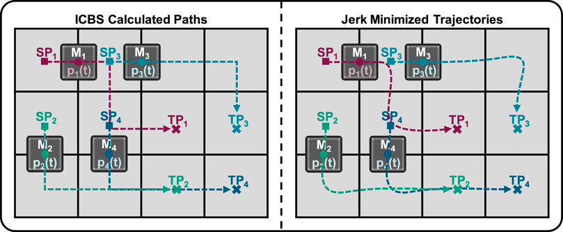
Figure 9. Schematic representation of the optimized and non-optimized trajectories.
The multi-agent path finding problem is initially solved by the ICBS, presented in Section 2.1. This results in collision-free trajectories being output as waypoints for all agents involved. However, these trajectories are not practical for real-world applications, as they do not prohibit abrupt changes in direction (see Figure 9, left). For this reason, these individual trajectories are minimized in terms of their jerks; in other words, the curves are smoothened and less abrupt (Figure 9, right). These individual optimized reference trajectories are then passed to the MPC, which ensures the collision-free execution of the MAPF solution. This is illustrated in Figure 4.
2.3 Development of a centralized model predictive control
To implement the CMPC, the acados software package is utilized (Verschueren et al., 2022). Its core, written in C, enables the use of optimal control methods for real-time applications, while interfaces for C++, Matlab, and Python offer versatile accessibility. These high-level interfaces use CasADi for modeling nonlinear functions and derivatives, allowing comparisons with other optimization libraries (Frey et al., 2023).
The workflow starts by defining the optimal control problem (OCP) using high-level interfaces, which simplifies the problem setup. Next, a self-contained C project is generated, which includes all the necessary functions and solvers needed to solve the OCP. To use this C project within Simulink, a MATLAB S-function is built. The S-function acts as a bridge, allowing Simulink to interface with the C code. This integration enables testing and validation of the control algorithm within Simulink. Once the model is successfully tested, the automatic code generation feature is used to deploy the solution on TwinCAT for real-time implementation.
2.3.1 Prediction model
The CMPC is designed to control multiple agents by solving a centralized optimization problem. Each agent, or mover, is modeled using double integrator dynamics, also known as the point-mass model, to represent its free movement in a two-dimensional (2D) plane. In both the simulation and experimental setup, the state variables (px, py, vx, vy) represent the Mover’s position and velocity, while the control inputs (ax, ay) represent accelerations. The action diagram is represented by Figure 10 (left) and a schematic drawing (right).
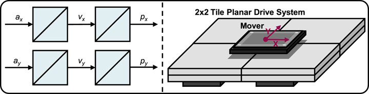
Figure 10. Simplified action diagram of the dynamics of a mover on a planar drive.
The agent state vector (xi) of an individual agent indexed with i and the individual agent control input vector (ui) are defined and form the following point mass model (Equations 6, 7):
For the CMPC, the following state-space model is derived to describe the dynamics of N agents, where each agent i has a state vector xi of size n and an input vector ui of size m. The overall state vector (x) and overall control input vector (u) for the N agents are defined as concatenations of the individual state and input vectors (Equation 8):
The state space representation is given as follows (Equation 9) and the dynamics of each agent are governed by a common system matrix
Each block A in the matrix A describes the internal dynamics of an individual agent, and each block B in the matrix B describes how the inputs affect the states of an individual agent.
2.3.2 Cost function
To fomulate the OCP, the following differentziable cost function (Equation 11) is used that penalizes the running costs ls(x(t),u(t)) and the final stage cost lf(x(tf)). JOCP is the total cost function to be minimized and thus is set 0 and formulated as follows:
subject to:
In this case, the running costs from the initial point in time (t0) to the final state time (tf) are integrated. ls is the stage cost function, which depends on the state x(t) and the control u(t). lf is the end cost portion only depending on the final state x(tf). The differential equation
For the implementation for model predictive control, the OCP must be time discretized, assuming the system input is constant during the sampling period, approximating the input signal by its staircase form. Therefore the multiple shooting method (Bock and Plitt, 1984) is used and employed directly due to the use of Acados. This method discretizes the time horizon into multiple segments and converts the OCP into a structured nonlinear programming problem with continuity constraints, enhancing numerical stability, parallel computation, and robustness to initial estimations.
subject to:
Equation 16 shows the discretized form of the OCP formulation. Here, the deviation between the state x and the reference state xref is minimized, as well as the deviation between the control input u and the reference control input uref, which is set to zero because there is no explicit reference and the control effort should be kept as low as possible.
2.3.3 Collision avoidance constraints
Due to collision avoidance constraints, movers are not allowed to operate in areas occupied by other movers and obstacles. This restriction makes the set of their motion non-convex, leading to a collision avoidance optimization problem that is inherently non-convex. Consequently, this problem falls into the category NP-hard problems (Canny, 1988).
Mathematically, the collision avoidance constraint between two movers M1 and M2 can be modeled using the Euclidean distance. p1(t) and p2(t) denote the positions of M1 and M2 at time t, respectively. The collision avoidance constraint ensures that the squared distance between M1 and M2 at any time t is greater than the square of a minimum safe distance dmin (Equation 22):
In the event that more than two movers are active within a feasible space, as shown in Figure 11, the collision avoidance constraint g(x(t)) is extended accordingly for each respective mover relationship. Further constraints are defined to restrict the x- and y-dimensions of the feasible space.
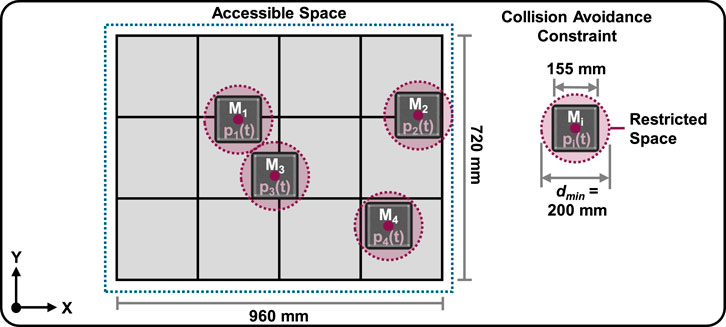
Figure 11. Mover collision avoidance constraint illustration.
Acados uses Sequential Quadratic Programming (SQP) for solving the OCP. SQP solves nonlinear optimization problems through a sequence of quadratic approximations, achieving superlinear convergence for smooth problems (Boggs and Tolle, 1995; Nocedal and Wright, 2006). This method iteratively linearizes the problem to update u(τ), efficiently computing optimal inputs. SQP is advantageous for motion planning in autonomous systems due to its computational efficiency, predictable load, and manageable memory requirements, making it suitable for real-time applications in embedded systems (Nocedal and Wright, 2006). Although Interior Point Methods (IPM) can application-dependent outperform SQP, their complexity and higher memory demands limit their practicality in embedded environments. For real-time tasks, the Real-Time Iteration (RTI) scheme (Diehl et al., 2005) provides suboptimal solutions in each time step, ensuring feasibility within small sampling times.
The SQP method addresses problems with nonlinear constraints by iteratively solving Quadratic Programming (QP) subproblems. In each subproblem, the objective function is approximated quadratically, and the constraints are linearized. For collision avoidance constraints, this involves linearizing the squared Euclidean distance constraint at each iteration and incorporating it into the QP subproblem. In this context, the High-Performance Interior Point Method (HPIPM) solver (Frison and Diehl, 2020) is utilized for solving these QP subproblems.
2.3.4 Implementation workflow
The implementation of the CMPC into a PLC environment from Beckhoff Automation (TwinCAT) involves multiple integration steps, using both software and hardware components. Figure 12 shows the toolchain for developing and deploying the CMPC algorithm.
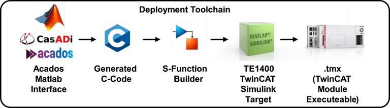
Figure 12. CMPC algorithm deployment toolchain for Beckhoff Automation systems.
The described optimization problem is exported to a JSON file, which serves as a basis for rendering templates via the Tera renderer. The Acados interface includes a MEX wrapper that, along with the generated C code, allows for integration with MATLAB. The next stage involves simulating and deploying the generated C code in Simulink. Since TwinCAT does not allow direct use of external libraries, the S-Function builder in Simulink is used to incorporate the algorithms written in C. This integration is crucial for testing, validating, and deploying the CMPC algorithm in a simulated environment. To ensure real-time execution on Beckhoff hardware, the TE1400 TwinCAT 3 Target for Simulink is used. This tool generates real-time executable code from the Simulink models using Simulink Coder, bridging the gap between simulation and real-world deployment. The result of this automatic code generation process is a function block that can be utilized within the TwinCAT environment. This function block is illustrated in Supplementary Material S5 and encapsulates the entire CMPC algorithm and provides an interface for integration with other components in the control system. The block includes inputs and outputs necessary for executing the CMPC logic, allowing seamless interaction with the hardware and facilitating real-time control operations.
3 Testing and validation
To demonstrate the capabilities of the developed CB-MPC framework, a magnetic planar drive system is utilized with a 3 x 4 tile configuration and with four active movers representing the agents; compare Figure 2. Physical dimensions are illustrated in Figure 11. For evaluating the CB-MPC performance regarding MAPF success rate, computation time and robustness, 10 path finding scenarios are defined representing different challenges for the solver. Figure 13 illustrates the setup for each scenario, highlighting the initial positions (■) and target positions (x) of each mover (M1 – M4). Movers that are locked in place but are still part of the MAPF problem are marked with an anchor. Tiles that are defined as not accessible obstacles are blackened.
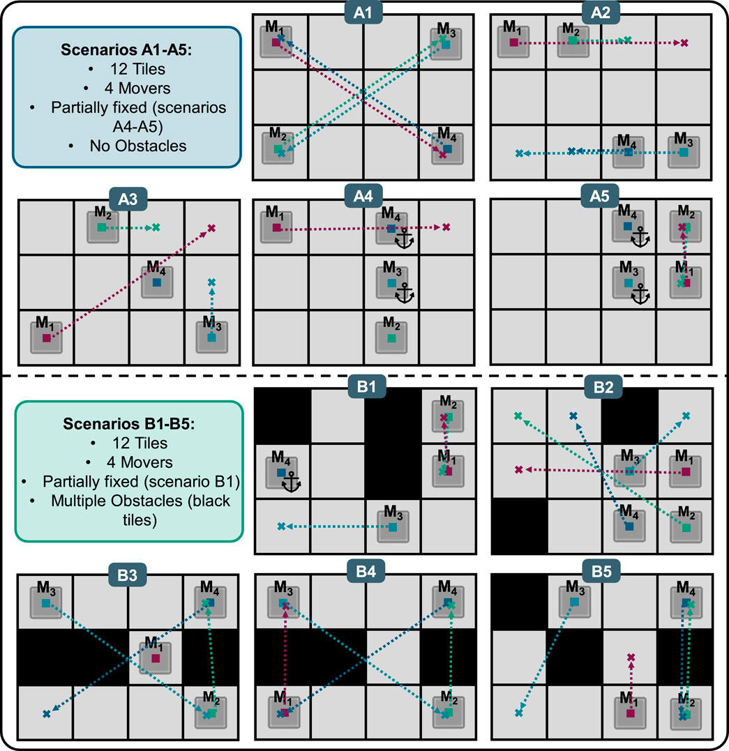
Figure 13. CB-MPC testing scenarios on a magnetic planar drive system.
3.1 Setup and configuration
The formulation of the optimization problem for the experimental setup is presented as follows. The objective is to minimize the deviation of each agent’s state and control inputs from their respective reference trajectories while considering collision avoidance and constraints on states and control inputs. The time-discretized OPC is defined as follows (Equation 23):
subject to:
Equation 24 declare discrete states for each agent. Equation 25 limits the acceleration of the movers to ±150 mm/s2. Equations 26, 27 limit the accessible area of the planar drive system in X- and Y-direction. Equation 28 limits the speeds of the movers to ±250 mm/s. Equation 29 defines the minimum distance that all movers must maintain to all other movers. dmin is specified to 200 mm during all tests, compare Figure 11.
The state vector for the four movers, with their respective positions and velocities is given by (Equation 33):
The Q matrix used for the state weights is a diagonal matrix of size 16 × 16, where the weights 1 and 0,6 alternate for position and velocity respectively. This weighting prioritizes the position limits over the velocity limits. The control input vector is given by (Equation 34):
The R matrix used for the accelarations weights is a diagonal matrix of size 8 × 8 with the following structure (Equation 35):
The CB-MPC framework is further configured with the hyperparameter settings listed in Table 1.
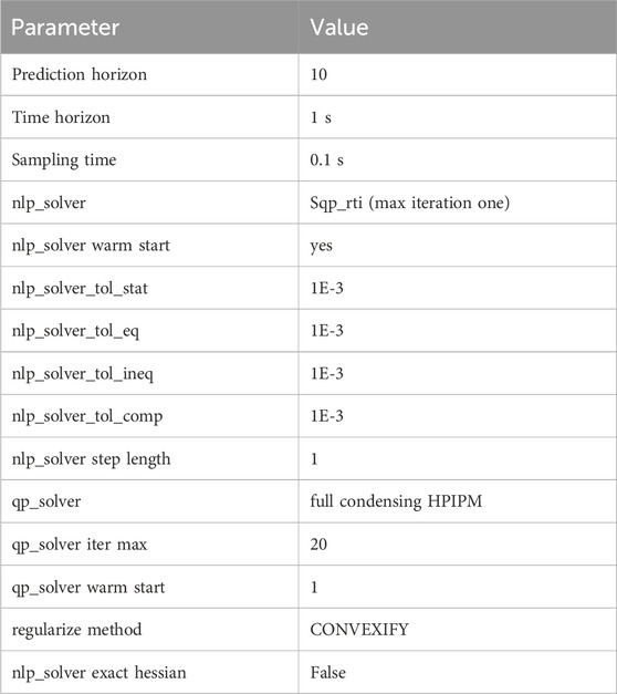
Table 1. CB-MPC hyperparameters.
3.2 Path finding performance evaluation
Table 2 presents the performance evaluation of the CB-MPC framework across a set of simple (A1-A5) and complex scenarios (B1-B5); compare Figure 13. These results highlight the framework’s ability to manage collision avoidance in MAS under different conditions.
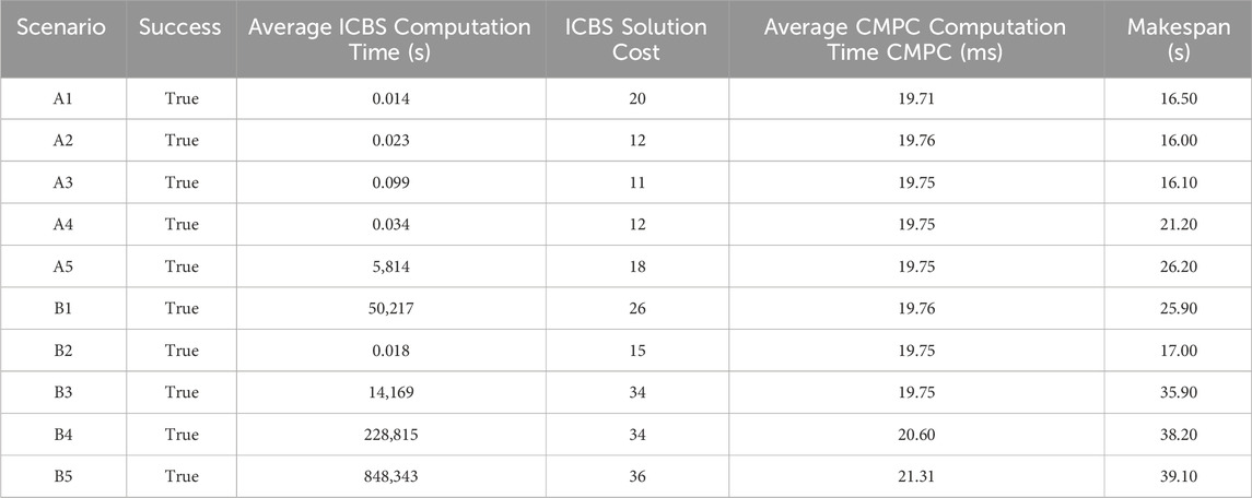
Table 2. Performance evaluation of CB-MPC across different scenarios.
All scenarios achieved a 100% success rate, indicating that CB-MPC can reliably finds collision-free paths. Even Scenario B5, where only one feasible path solution exists, could be solved. The ICBS solution times range from 0.014 to 5,814 s for the A scenarios and from 0.018 to 848,343 s for the B scenarios, indicating the higher complexity. The ICBS solution costs range from 11 to 36. The average CMPC computation times are stable around 20 ms. The makespan, describing the path execution time, ranges from 16 to 39.1 s.
A video showing the motion planning of the movers for all ten scenarios is accessible via the following link: https://owncloud.fraunhofer.de/index.php/s/XRJ02l5Db5MjjOo. This video provides a demonstration of the CB-MPC framework’s performance across different scenarios.
In addition to the uninterrupted execution of all scenarios, another run was performed with all scenarios, in which Mover M1 was temporarily blocked during the execution of the paths by holding it manually in place and then releasing it again after a few seconds. This simulates an external disturbance. In all scenarios, it was observed that this disturbance only affected Mover M1 if Mover M1 did not force other movers to stop due to a blocked path. In no scenario did the disturbance cause a collision or an error. After the disturbance, the paths were completed identically to the undisturbed trial. The makespan was extended in accordance with the duration of the disturbance.
The observations regarding the trajectories executed, which can be seen in the linked videos, are described and discussed hereafter.
4 Discussion
The successful solution of all scenarios demonstrates the suitability of ICBS for offline calculation of mover paths and thus for solving the MAPF problems. The test series with external disturbance and the result that no collisions or errors were generated demonstrate the suitability of MPC for the live execution of the path plans. A proof of principle that CB-MPC is suitable for motion planning on multi-agent systems was thus experimentally provided using a magnetic planar drive MAS demonstrator.
The performance evaluation of the ICBS in Table 2 shows that the solution of some MAPF scenarios (A5, B1, B3, B4, B5) requires significantly more computing time (>1 s) and may therefore not be suitable for applications requiring fast response times. It was observed that the increased computing time occurs more frequently with specific properties of the scenarios: Firstly, when two movers must change positions in a narrow space, which causes both movers to move further away from their destination to enable the position swap. Secondly, when movers that have already reached their destination, must move away so that the other movers can reach their destination. Thirdly, when only few theoretical solutions exist for the MAPF problem in general. From these observations, it can be deduced that the quotient of free space and space blocked by movers should be above a certain value in order to reduce the complexity of the MAPF problem. At the same time, it must also be ensured that there are as few bottlenecks as possible. These bottleneck locations can be identified by analyzing all durations that individual tiles are blocked by traveling movers within a MAPF scenario. This could be visualized with a traffic heatmap. If these two aspects are considered when designing the layout of the system, the solution speed can be increased.
The number of agents involved in route planning also affects the performance of the solver. The scalability of the algorithm is a major limitation. With increasing the number of movers on the system, the number of collision constraints grows quadratically, significantly raising computational complexity. This increase leads to a greater number of optimization variables that the CB-MPC must solve in each iteration, resulting in higher computational loads. Also, more SQP iterations are required for the MPC to find acceptable solutions with more agents. Supplementary Material S6 investigates the average MPC computation time depended on the number of agents and shows an exponential growth from 19.7 ms (4 Mover) to 2,866.9 ms (10 Mover). This would accordingly increase the MAPF makespan drastically. This underscores the need for advanced heuristics and distributed control strategies to maintain scalability and enhance performance. Approaches to modify the algorithm to a non-optimal solver are also conceivable in order to increase scalability.
One criticism of this work is that no direct comparison was made between different established MAPF approaches and the CB-MPC developed. A direct comparison using the same scenarios would provide more quantitative statements about the performance and potentials. Such comparative studies should be carried out in the future in order to provide evidence that the state of the art was improved.
5 Conclusion
Building upon the results presented, the CB-MPC framework demonstrates its capability to handle complex multi-agent pathfinding and collision avoidance in dynamic environments and guarantees optimality. The integration of ICBS with MPC proves to be effective in balancing optimal path planning and real-time adaptability, which are crucial in modern industrial applications. CB-MPC allows agents to navigate between stations and perform nonlinear process steps without collisions. This adaptability is particularly beneficial in scenarios requiring customized processes and dynamic routing. The inclusion of a minimum jerk trajectory optimizer ensures smooth paths and reduces abrupt movements, enhancing overall system safety.
The main limitations of CB-MPC are linked to its scalability issues. As the number of agents grows, the framework struggles with the exponential increase in collision constraints and optimization variables, impacting real-time performance. Reliance on Euclidean distance for collision detection may introduce inefficiencies. Overall, CB-MPC offers a practical approach to multi-agent pathfinding and collision avoidance but requires further development to address its scalability limitations.
Data availability statement
The original contributions presented in the study are included in the article/Supplementary Material, further inquiries can be directed to the corresponding author.
Author contributions
KJ: Conceptualization, Data curation, Investigation, Methodology, Project administration, Supervision, Validation, Visualization, Writing – original draft, Writing – review and editing. AH: Conceptualization, Formal Analysis, Investigation, Methodology, Software, Validation, Writing – original draft. CS: Conceptualization, Data curation, Methodology, Supervision, Writing – review and editing. FE: Conceptualization, Methodology, Software, Supervision, Writing – review and editing. LF: Investigation, Methodology, Software, Writing – review and editing. LH: Project administration, Writing – review and editing. BN: Funding acquisition, Project administration, Resources, Writing – review and editing. RS: Resources, Writing – review and editing, Funding acquisition.
Funding
The author(s) declare that no financial support was received for the research and/or publication of this article.
Conflict of interest
The authors declare that the research was conducted in the absence of any commercial or financial relationships that could be construed as a potential conflict of interest.
Generative AI statement
The author(s) declare that Generative AI was used in the creation of this manuscript. Generative AI was only used for translations and to help with linguistic phrasing.
Publisher’s note
All claims expressed in this article are solely those of the authors and do not necessarily represent those of their affiliated organizations, or those of the publisher, the editors and the reviewers. Any product that may be evaluated in this article, or claim that may be made by its manufacturer, is not guaranteed or endorsed by the publisher.
Supplementary material
The Supplementary Material for this article can be found online at: https://www.frontiersin.org/articles/10.3389/fcteg.2025.1645918/full#supplementary-material
References
Albin Rajasingham, T. (2021). Nonlinear model predictive control of combustion engines: from fundamentals to applications. Cham: Springer International Publishing AG. Available online at: https://ebookcentral.proquest.com/lib/kxp/detail.action?docID=6577310.
Beckhoff Automation GmbH and Co. KG (2025). TwinCAT 3 ADS introduction, Verl, Germany: Beckhoff Automation GmbH and Co. Available online at: https://download.beckhoff.com/download/Document/Catalog/Beckhoff_TwinCAT3_d.pdf (Accessed 3 June 2025).
Bock, H. G., and Plitt, K. J. (1984). A multiple shooting algorithm for direct solution of optimal control problems. IFAC Proc. Vol. 17 (2), 1603–1608. doi:10.1016/s1474-6670(17)61205-9
Boyarski, E., Felner, A., Sharon, G., and Stern, R. (2015). Don't split, try to work it out: bypassing conflicts in multi-agent pathfinding. Proc. Int. Conf. Automated Plan. Sched. 25, 47–51. doi:10.1609/icaps.v25i1.13725
Brecher, C. (2012). Integrative production technology for high-wage countries. Berlin, Heidelberg: Springer Berlin Heidelberg.
C. Brecher, F. Klocke, R. Schmitt, and G. Schuh (2017). Internet of Production für agile Unternehmen: AWK Aachener Werkzeugmaschinen-Kolloquium 2017, 18. bis 19. Mai, Aachen, Apprimus Verlag.
Canny, J. F. (1988). The complexity of robot motion planning. (Cambridge, Mass: Massachusetts Institut of Technology, Diss).
Diehl, M., Bock, H. G., and Schlöder, J. P. (2005). A real-time iteration scheme for nonlinear optimization in optimal feedback control, SIAM Journal on Control and Optimization, 43, 5, 1714–1736.
Duchoň, F., Babinec, A., Kajan, M., Beňo, P., Florek, M., Fico, T., et al. (2014). Path planning with modified a star algorithm for a mobile robot. Procedia Eng. 96, 59–69. doi:10.1016/j.proeng.2014.12.098
Felner, A., Li, J., Boyarski, E., Ma, H., Cohen, L., Kumar, T. K. S., et al. (2018). Adding heuristics to conflict-based search for multi-agent path finding. Proc. Int. Conf. Automated Plan. Sched. 28, 83–87. doi:10.1609/icaps.v28i1.13883
Frison, G., and Diehl, M. (2020). HPIPM: a high-performance quadratic programming framework for model predictive control, IFAC-PapersOnLine, 53, 2, 6563–6569.
Frey, J., Schutter, J. de, and Diehl, M. (2023). “Fast integrators with sensitivity propagation for use in CasADi,” in 2023 European control conference (ECC). Bucharest, Romania: IEEE, 1–6.
Gao, J., Li, Y., Li, X., Yan, K., Lin, K., and Wu, X. (2024). A review of graph-based multi-agent pathfinding solvers: from classical to beyond classical. Knowledge-Based Syst. 283, 111121. doi:10.1016/j.knosys.2023.111121
Göppert, A., Hüttemann, G., Jung, S., Grunert, D., and Schmitt, R. (2018). Frei verkettete montagesysteme. Z. für Wirtsch. Fabr. 113 (3), 151–155. doi:10.3139/104.111889
Hu, S. J., Ko, J., Weyand, L., ElMaraghy, H. A., Lien, T. K., Koren, Y., et al. (2011). Assembly system design and operations for product variety. CIRP Ann. 60 (2), 715–733. doi:10.1016/j.cirp.2011.05.004
Janning, K., Koenig, S., Herbst, L., Niessing, B., and Schmitt, R. H. (2025). Development of an end-to-end automated production concept for extrusion-based additive manufacturing of personalized medical scaffolds. Front. Manuf. Technol. 5. doi:10.3389/fmtec.2025.1572842
Komesker, S., Motsch, W., Popper, J., Sidorenko, A., Wagner, A., and Ruskowski, M. (2022). 'Enabling a multi-agent system for resilient production flow in modular production systems. Procedia CIRP 107, 991–998. doi:10.1016/j.procir.2022.05.097
Li, J., Boyarski, E., Felner, A., Ma, H., and Koenig, S. (2019a). Improved heuristics for multi-agent path finding with conflict-based search: preliminary results. Proc. Int. Symposium Comb. Search 10 (1), 182–183. doi:10.1609/socs.v10i1.18481
Li, J., Harabor, D., Stuckey, P. J., Felner, A., Ma, H., and Koenig, S. (2019b). Disjoint splitting for multi-agent path finding with conflict-based search. Proc. Int. Conf. Automated Plan. Sched. 29, 279–283. doi:10.1609/icaps.v29i1.3487
Liu, S., Feng, B., Bi, Y., and Yu, D. (2024). An integrated approach to precedence-constrained multi-agent task assignment and path finding for mobile robots in smart manufacturing. Appl. Sci. 14 (7), 3094. doi:10.3390/app14073094
Lozer, F., Scalera, L., Boscariol, P., and Gasparetto, A. (2025). Planning optimal minimum-jerk trajectories for redundant robots. Robotics Aut. Syst. 192, 105049. doi:10.1016/j.robot.2025.105049
Nocedal, J., and Wright, S. J. (2006). Numerical optimization [Online], New York, NY: Springer. Available online at: http://www.loc.gov/catdir/enhancements/fy0818/2006923897-d.html.
Sharon, G., Stern, R., Felner, A., and Sturtevant, N. (2012). Meta-agent conflict-based search for optimal multi-agent path finding. Proc. Int. Symposium Comb. Search 3 (1), 97–104. doi:10.1609/socs.v3i1.18244
Sharon, G., Stern, R., Felner, A., and Sturtevant, N. R. (2015). Conflict-based search for optimal multi-agent pathfinding. Artif. Intell. 219, 40–66. doi:10.1016/j.artint.2014.11.006
Stern, R. (2019). “Multi-agent path finding – an overview,” in Artificial intelligence: 5th RAAI summer School, dolgoprudny, Russia, july 4–7, 2019, tutorial lectures. Editors G. S. Osipov, A. I. Panov, and K. S. Yakovlev (Cham: Springer), 96–115.
Stern, R., Sturtevant, N., Felner, A., Koenig, S., Ma, H., Walker, T., et al. (2019). Multi-agent pathfinding: definitions, variants, and benchmarks.
The MathWorks, Inc (2021). Generate minimum jerk trajectory. Available online at: https://www.mathworks.com/help/robotics/ug/generate-minimum-jerk-trajectory.html.
Verschueren, R., Frison, G., Kouzoupis, D., Frey, J., van Duijkeren, N., Zanelli, A., et al. (2022). 'acados—a modular open-source framework for fast embedded optimal control. Math. Program. Comput. 14 (1), 147–183. doi:10.1007/s12532-021-00208-8
Wang, R., Zhang, L., and Yang, K. (2024). 'Overview of the development of planar motor technology. Energies 17 (16), 3955. doi:10.3390/en17163955
Q. Yang, and M. J. Wooldridge (2015). Proceedings of the twenty-fourth international joint Conference on artificial intelligence: Buenos Aires, Argentina, 25-31 july 2015, palo alto, California, AAAI press international joint conferences on artificial intelligence.
Keywords: conflict-based search, model predictive control, multi-agent coordination, path planning, collision avoidance, sequential quadratic programming, planar drive, automation
Citation: Janning K, Housin A, Schulte C, Erkens F, Frenken L, Herbst L, Nießing B and Schmitt RH (2025) Conflict-based model predictive control for multi-agent path finding experimentally validated on a magnetic planar drive system. Front. Control Eng. 6:1645918. doi: 10.3389/fcteg.2025.1645918
Received: 12 June 2025; Accepted: 09 July 2025;
Published: 31 July 2025.
Edited by:
Giulio Ferro, University of Genoa, ItalyReviewed by:
Anca Maxim, Gheorghe Asachi Technical University of Iași, RomaniaCan Zhao, Northeastern University, China
Copyright © 2025 Janning, Housin, Schulte, Erkens, Frenken, Herbst, Nießing and Schmitt. This is an open-access article distributed under the terms of the Creative Commons Attribution License (CC BY). The use, distribution or reproduction in other forums is permitted, provided the original author(s) and the copyright owner(s) are credited and that the original publication in this journal is cited, in accordance with accepted academic practice. No use, distribution or reproduction is permitted which does not comply with these terms.
*Correspondence: Kai Janning, a2FpLmphbm5pbmdAaXB0LmZyYXVuaG9mZXIuZGU=