 Pablo Amedo Martinez
1
Pablo Amedo Martinez
1 Alexander Deisting2Heriques Frandini Gatti3
 Diego González-Díaz
1
Diego González-Díaz
1
 Adam John Lowe
3*Krishanu Majumdar3Konstantinos Mavrokoridis3Marzio Nessi4Barney Philippou3Francesco Pietropaolo4
Adam John Lowe
3*Krishanu Majumdar3Konstantinos Mavrokoridis3Marzio Nessi4Barney Philippou3Francesco Pietropaolo4
 Sudikshan Ravinthiran
3Filippo Resnati4Adam Roberts3Angela Saá Hernández1Christos Touramanis3Jared Vann3
Sudikshan Ravinthiran
3Filippo Resnati4Adam Roberts3Angela Saá Hernández1Christos Touramanis3Jared Vann3
- 1 Instituto Galego de Física de Altas Enerxías, Universidade de Santiago de Compostela, Santiago de Compostela, Spain
- 2 Institute of Physics, Johannes Gutenberg University Mainz, Mainz, Germany
- 3 Department of Physics, University of Liverpool, Liverpool, United Kingdom
- 4 European Organization for Particle Physics (CERN), Geneva, Switzerland
The ARIADNE programme is focused on the development of a scalable optical readout system for use in future ktonne LAr neutrino experiments, providing high tracking capability and low energy thresholds. Following demonstration at the 1 tonne scale (ARIADNE detector), a 20 tonne experiment has been performed at the CERN Neutrino Platform (
1 Introduction
Traditional wire-based readout methods for Liquid Argon Time Projection Chambers (LAr TPCs) are facing a number of engineering and technological challenges as the next-generation of LAr neutrino experiments see ktonne-scale active volumes. These challenges stem from the various experimental requirements such as spatial resolution and energy thresholds. Therefore, alternative methods of readout are now being looked at to both compliment existing technologies and offer cost-efficient solutions without sacrificing performance. A detailed comparison of LAr TPC readout methods, including the optical readout approach described in this paper, is available in (Majumdar and Mavrokoridis, 2021).
The ARIADNE program has successfully demonstrated the viability of optical readout for dual-phase LAr TPCs using fast, high resolution Timepix3 cameras (Fisher-Levine and Nomerotski, 2016). This includes the readout of the 1 tonne ARIADNE detector at Liverpool with the use of a Thick Gaseous Electron Multiplier (THGEM) to image through-going muons (Hollywood et al., 2020; Lowe et al., 2020). Demonstrating the further scalability of ARIADNE technology is vital if this technology is to be considered an option for large-scale neutrino experiments such as DUNE (DUNE Collaboration, 2018).
Built for testing the vertical drift Charge Readout Planes (CRPs) (DUNE Collaboration, 2023), the ProtoDUNE “cold box” offers an ideal test bed for a modular ARIADNE Light Readout Plane (LRP). This paper begins with an overview of the ARIADNE detection principle and how this approach was scaled up for
2 Materials and methods
2.1 ARIADNE detection principle
In contrast to traditional LArTPC charge readout approaches, ARIADNE takes advantage of the scintillation light generated by an amplification stage within the detector. When an ionising particle passes through the detector volume, electrons are liberated from argon atoms and primary scintillation light (S1) is emitted. This primary scintillation light can be detected and used to give a
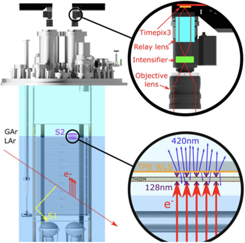
Figure 1. The ARIADNE detection principle. Timepix3 cameras image the secondary scintillation light generated within the THGEM holes in a dual-phase LAr TPC.
Given the optical nature of the readout, a wide range of commercial/off-the-shelf lenses and optical components can be utilised to control the Field-Of-View (FoV), spatial resolution, etc. Each hit the sensor records provides the X,Y position of the hit along with a 1.6ns resolution timestamp (Time of Arrival - ToA) and a 10-bit intensity value (Time over Threshold - ToT). This intensity value is a result of charge accumulation in the pixel electronics which discharges at a constant rate until the amount drops below a set threshold; at this point a ToT value is then determined. Given that the drift velocity of the detector is known, the X,Y and ToA allow for a full 3D reconstruction which can be combined with the S1
The readout is ‘Event-Based’, or data-driven, meaning that only the pixels registering a hit have their data saved so that all data is zero suppressed as standard. This provides for continuous, trigger-free readout and real-time viewing of data-stream. The Timepix3 chip itself is comprised of
Since the cameras are mounted on the outside of the TPC, the readout is completely decoupled from the internal TPC electronics, protecting it from any noise induced by the high voltages of the field cage or cathode. In addition, the technology can be easily accessed for maintenance and future upgrades. For example, Timepix4 has an improved timing resolution of approximately 200ps and larger sensor size of
The ability to image a large active area per single camera is a key advantage of the ARIADNE readout. As detailed later in this paper, one visible light intensifier Timepix3 camera was used to image 1 m
2.2 The
detector components
The next-generation of large scale liquid argon neutrino detectors, such as DUNE, present a number of technological challenges and have large potential to benefit from novel readout techniques (Abed Abud et al., 2024). Given the aforementioned benefits that ARIADNE readout can provide for LArTPCs,
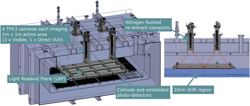
Figure 2. A CAD model of the
2.2.1 Visible image intensifier timepix setup
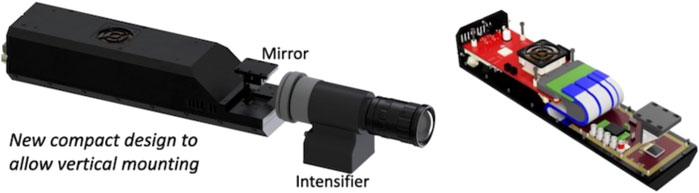
Figure 3. Timepix3 camera setup with redesigned housing.
2.2.2 VUV sensitive image intensifier timepix setup
In order to mitigate the need for the use of wavelength shifters and to increase the light collection efficiency, a custom-made VUV sensitive image intensifier was integrated to one of the Timepix3 cameras. The intensifier is able to directly detect the 128 nm secondary scintillation light produced from the THGEMs and this is relayed to the Timepix3 camera.
Image intensifiers are designed to be sensitive to specific wavelengths of interest through tailoring the photocathode, i.e., the Photonis Cricket mentioned earlier is designed for the visible part of the Electromagnetic (EM) spectrum. A prototype image intensifier, with a photocathode sensitive to VUV light, was purchased from Photek (Photek, 2025) for R&D, assessing its feasibility for future runs.
The quantum efficiency of the VUV image intensifier overlaid with the scintillation spectrum of argon can be seen in Figure 4. Included in this figure is also the scintillation spectrum of xenon, highlighting the potential to use this approach within xenon detectors. In particular, the Photonis image intensifier (Byrnes et al., 2023), has a quoted Quantum Efficiency (QE) of approximately 22% which is an improvement on the approximately 5% achieved by the current Photek intensifier as seen in Figure 4.
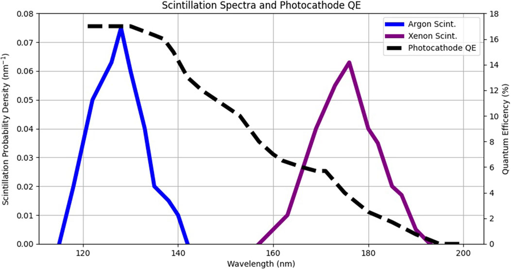
Figure 4. The Quantum Efficiency (QE) spectrum (shown in black) of the VUV image intensifier used within
Most common lens materials will not transmit VUV wavelengths and so alternative materials for both focusing and the window of the intensifier are needed. For the wavelength of light emitted by argon scintillation, the two best-performing materials available are Lithium fluoride (LiF) and Magnesium fluoride (
The layout of the intensifier itself is presented in Figure 5. The Caesium Iodide (CsI) coated Microchannel Plates (MCPs) are 18.8 mm in diameter and 4.171 mm from the back of the input window. Mounted to the MCPs is the phosphor screen which again is 18.8 mm in diameter. It is this screen that the Timepix3 is focused on for readout.
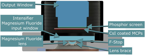
Figure 5. A CAD model showing the internals of the Photek VUV intensifier. The adjustable lens brace and f-stop were designed and added by the ARIADNE group.
The lens design was based on the following constraints; dimensions of the intensifier, the size of the photocathode, the height above the LRP the lens will sit and the desired field-of-view. The final lens used in the setup is 5 mm in diameter, 11 mm focal length and operated at a speed of f/3. The Timepix3 coupled to a VUV sensitive light intensifier had a calculated field-of-view 0.8 m
2.2.3 Light readout plane (LRP)
The LRP is the first key component in the
The LRP consists of the extraction grids, glass-THGEMs and Wavelength Shifting (WLS) polyethylene naphthalate (PEN) layer which are all fixed at well-defined positions within the structure. Figure 6 shows the LRP support frame and a cross-section of the structure.
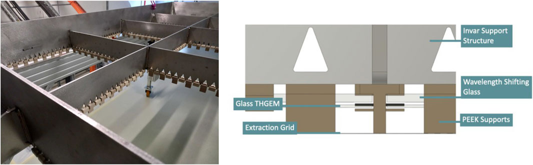
Figure 6. (Left) The invar support frame at CERN. (Right) A CAD model of the LRP cross-section.
2.2.4 Invar support frame
The support frame is designed to keep the three layers of the LRP at the correct distance from each other as the structure cools to cryogenic temperatures (LAr is −185 °C). In addition, the structure minimises the stress on the glass as the structure cools.
In order to minimise the stress on the glass components, the coefficients of thermal expansion
The frame itself is constructed out of 22 individual Invar parts, waterjet-cut from larger blanks. The blanks were all machined to a thickness of 6.0
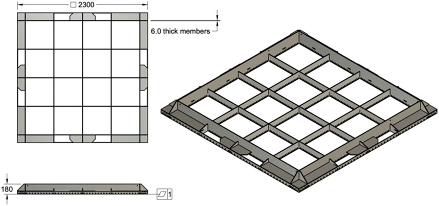
Figure 7. Technical drawing of the Invar support frame showing the dimensions of the frame.
To secure the layers of the LRP into the support structure, a set of PEEK pieces are fastened into holes cut into the frame. The Invar frame consists of 16 segments, within each of these segments the PEEK pieces alternate between those which support the extraction grid and those that secure in place the THGEMs and WLS layers.
2.2.5 Extraction grid
For
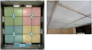
Figure 8. (Left) The THGEM connections that form the four quadrants. (Right) The modular extraction grid.
For the entire
2.2.6 Glass-THGEMs
The
The THGEMs were electrically interconnected using copper tabs that link groups of four THGEMs together. Each THGEM had one top connection and one bottom connection to the adjacent THGEM in each group of four. This arrangement can be seen in Figure 8.
2.2.7 Wavelength shifting layer
Given the close match between the emission spectra for PEN and tetraphenyl-butadiene (TPB) wavelength shifters (discussed in detail within (Kuźniak et al., 2019)), the group has investigated various grades of PEN for use within
Testing of different grades and thicknesses of PEN, in order to decide which one to use within
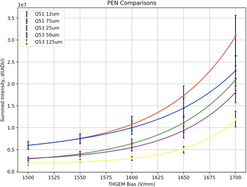
Figure 9. This figure shows a selection of the summed intensity of light, using an alpha source, for different grades and thicknesses of PEN film in tests conducted at Liverpool using the 40L demonstrator vessel. This figure was taken from (Philippou, 2022).
The largest summed intensity came from the Q51 12
2.3 Cathode and ARAPUCAS
The “cold box” cathode is a wire-mesh frame supported by a combination of stainless steel and PTFE, which is connected to a power supply capable of up to −30 kV. Embedded within the cathode are a combination of X-ARAPUCAS and ARAPUCA cells (Machado and Segreto, 2016), which are novelly powered over fibre (Arroyave et al., 2024). ARAPUCAS are the photocells chosen for the first two DUNE modules after their successful runs in both ProtoDUNEs.
2.4 Detector commissioning and operation
Once constructed, the LRP was suspended from the roof of the “cold box” via four stainless steel cables, the height of which can be individually adjusted using four cranks on the lid of the cryostat. In Figure 10, the cables for suspending the LRP underneath the lid are shown. The second image shows the LRP secured under the roof before it was lifted on top of the “cold box”. It was then secured on top of the “cold box” vessel before argon-flushing to remove the trapped impurities. Once this was complete, filling with LAr commenced.
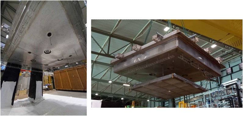
Figure 10. (Left) The roof of the “cold box” with the four camera penetrations in the centre and surrounding those the four lifting hooks that the LRP is suspended from. (Right) Lifting the roof with the LRP attached on the bottom side into the trench where the cryostat is located.
The purified LAr was fed from ProtoDUNE-DP into the “cold box”. This liquid comes filtered by the CERN cryogenic facility and purity is monitored using a Si-PM, mounted on the side of the “cold box”. The purity was continuously monitored and the electron lifetime maintained at approximately 0.5 ms. When the purity dropped below this value the vessel was emptied and refilled - this was done twice during the initial 3 weeks of running.
2.4.1 LRP levelling
For efficient dual-phase operation of the detector, it was necessary to maintain the liquid level at approximately halfway between the extraction grid and THGEM in the 15 mm gap. In order to achieve this, the LRP has a PT100 temperature sensor and a capacitance level meter at each corner as shown in Figure 11. The PT100s are positioned in line with the extraction grid and are crucial for ensuring the LRP was level before lowering the structure.
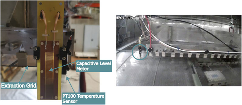
Figure 11. (Left) The liquid argon level sensing at each corner of the LRP. (Right) View of the inside of the “cold box”, during filling, with one corner PT100 and level sensor circled. The red cable visible is the high voltage supply for the extraction grid.
Once the first PT100 was reading LAr temperature, it was then known that the liquid has reached the level of the extraction grid at that position. The filling was then stopped and it was now important to ensure that the LRP is level to the liquid surface. At this stage, the height of the LRP was controlled by hand cranks. By using these hand cranks, the height was adjusted at each corner of the LRP so that all PT100s are measuring liquid temperature. Monitoring was then switched to a combination of the webcam installed in the “cold box”, also seen in Figure 11, and the capacitance level meters (part of the slow control system provided by CERN). The main use of the capacitance meters is for ensuring that all four sides are being lowered at the same rate (relative distance measurement was performed).
2.4.2 TPC biasing
With the cathode voltage set at −15 kV and the extraction grid biased to −6kV, the THGEMs were then biased (typically −2.7 kV). After initially biasing the THGEMs, it was found that grounding the top of the THGEMs and adjusting the bias on the bottom of each quadrant was best for achieving the highest stable THGEM potential.
3 Results
Data collection for the first
3.1 Gallery of events
Presented in Figure 12 are a selection of events from two quadrants of the
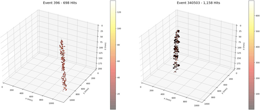
Figure 12. (Left) Visible light cosmic muon event. (Right) VUV light cosmic muon event. The difference in the track appearance is explained by the difference in response (MCP gain, phosphor screen brightness) between the visible and VUV intensifiers.
3.2 Cosmic muon analysis
For the visible and VUV quadrant of the detector, a number of analyses were conducted, the results of which can be seen in Figures 13, 14. A heat map was first produced from 30 s of raw hits. In both heat maps the Invar frame is visible, illustrating the amount of light produced in a short frame of time as well as verifying the field-of-view. The FoV for the visible light intensifier setup was determined to be approximately 1.1 m
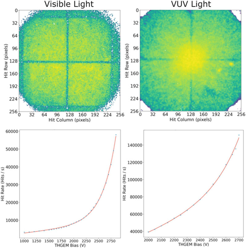
Figure 13. (Top Left) 30 s heat map of one visible quadrant of
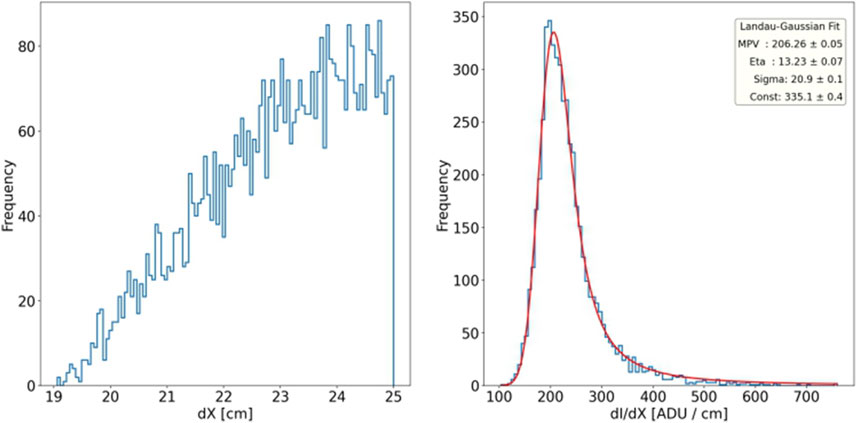
Figure 14. (Left) The
Finally, by using a selection of clustered through-going muon events (those that traverse the majority of the drift region), it is possible to obtain a calibration for the detector. Clustered events are groups of hits that fall within limits set by the user based on pixel separation in X,Y and ToA. Each event’s measured light intensity
The Most-Probable-Value (MPV) of the Landau-Gaussian fit applied to the data (as seen in Figure 14) can be equated to the known deposition rate for cosmic muons in liquid argon (2.12 MeV/cm) to determine a calibration. For the visible light intensifier data, the Analogue-to-Digital Unit (ADU) per MeV is determined to be (100.15
Using the fits seen in Figure 14, the energy resolution was calculated to be approximately 11.5%.
4 Discussion
This paper provides a comprehensive overview of the
The
By collecting cosmic muon data, the FoV for the cameras (1.1 m
Planning is currently taking place for the next test of this technology on an even larger scale relevant for DUNE. This would see the ProtoDUNE NP-02 cryostat instrumented with an 6 m
The ARIADNE project has demonstrated the scalability of this high resolution, ultra-fast optical readout. The ability to image large areas of the detector with very few cameras makes this a cost-effective readout method without sacrificing physics capabilities. The number of cameras required to instrument a DUNE far-detector will depend on the desired spatial resolution for each camera. For example, 320 Timepix4 cameras will be able to image the 60 m
Data availability statement
The raw data supporting the conclusions of this article will be made available by the authors, without undue reservation.
Author contributions
PM: Writing – review and editing. AD: Writing – review and editing. HG: Writing – review and editing, Supervision. DG-D: Writing – review and editing. AL: Writing – original draft, Writing – review and editing. KrM: Writing – review and editing. KoM: Writing – original draft, Writing – review and editing. MN: Writing – review and editing. BP: Writing – review and editing. FP: Writing – review and editing. SR: Writing – review and editing, Writing – original draft. FR: Writing – review and editing. AR: Writing – original draft, Writing – review and editing. AH: Writing – review and editing. CT: Writing – review and editing. JV: Writing – review and editing.
Funding
The author(s) declare that financial support was received for the research and/or publication of this article. This research was funded by STFC UKRI Grant No. ST/T007265/1 and ARIADNE ERC Grant No. 677927.
Acknowledgments
The authors would like to thank the members of the Mechanical Workshop of the University of Liverpool’s Physics Department, for their contributions and invaluable expertise. The authors would also like to thank the members of the CERN Neutrino Platform cryogenic team.
Conflict of interest
The authors declare that the research was conducted in the absence of any commercial or financial relationships that could be construed as a potential conflict of interest.
The reviewer MB declared a past collaboration with the author DGAD to the handling editor.
Generative AI statement
The author(s) declare that no Generative AI was used in the creation of this manuscript.
Any alternative text (alt text) provided alongside figures in this article has been generated by Frontiers with the support of artificial intelligence and reasonable efforts have been made to ensure accuracy, including review by the authors wherever possible. If you identify any issues, please contact us.
Publisher’s note
All claims expressed in this article are solely those of the authors and do not necessarily represent those of their affiliated organizations, or those of the publisher, the editors and the reviewers. Any product that may be evaluated in this article, or claim that may be made by its manufacturer, is not guaranteed or endorsed by the publisher.
References
Abed Abud, A., Abi, B., Acciarri, R., Acero, M., Adames, M., Adamov, G., et al. (2024). DUNE phase II: scientific opportunities, detector concepts, technological solutions. J. Instrum. 19, P12005. doi:10.1088/1748-0221/19/12/p12005
Arroyave, M., Behera, B., Cavanna, F., Feld, A., Guo, F., Heindel, A., et al. (2024). Characterization and novel application of power over fiber for electronics in a harsh environment. J. Instrum. 19, P10019. doi:10.1088/1748-0221/19/10/p10019
Byrnes, N., Parmaksiz, I., Adams, C., Asaadi, J., Baeza-Rubio, J., Bailey, K., et al. (2023). Next-crab-0: a high pressure gaseous xenon time projection chamber with a direct vuv camera based readout. J. Instrum. 18, P08006. doi:10.1088/1748-0221/18/08/p08006
Chardonnet, E. (2020). The dune dual-phase liquid argon tpc. J. Instrum. 15, C05064. doi:10.1088/1748-0221/15/05/c05064
DUNE Collaboration (2018). The DUNE far detector interim design report volume 1: physics, technology and strategies. arxiv Preprint.
DUNE Collaboration (2023). The DUNE far detector vertical drift technology, technical design report. arxiv Preprint.
Fisher-Levine, M., and Nomerotski, A. (2016). Timepixcam: a fast optical imager with time-stamping. J. Instrum. 11, C03016. doi:10.1088/1748-0221/11/03/c03016
Gehman, V., Seibert, S., Rielage, K., Hime, A., Sun, Y., Mei, D. M., et al. (2011). Fluorescence efficiency and visible re-emission spectrum of tetraphenyl butadiene films at extreme ultraviolet wavelengths. Nucl. Instrum. Methods Phys. Res. Sect. A Accel. Spectrom. Detect. Assoc. Equip. 654, 116–121. doi:10.1016/j.nima.2011.06.088
Hollywood, D., Majumdar, K., Mavrokoridis, K., McCormick, K., Philippou, B., Powell, S., et al. (2020). Ariadne—a novel optical lartpc: technical design report and initial characterisation using a secondary beam from the cern ps and cosmic muons. J. Instrum. 15, P03003. doi:10.1088/1748-0221/15/03/p03003
Horiba (2025). What detector can be used together with a vuv system? Minami-ku, Japan: Horiba. Available online at: https://www.horiba.com/int/scientific/technologies/vacuum-ultra-violet-spectroscopy/vuv-system-detector/.
Kuźniak, M., Broerman, B., Pollmann, T., and Araujo, G. (2019). Polyethylene naphthalate film as a wavelength shifter in liquid argon detectors. Eur. Phys. J. C 79, 291–296. doi:10.1140/epjc/s10052-019-6810-8
Llopart, X., Alozy, J., Ballabriga, R., Campbell, M., Casanova, R., Gromov, V., et al. (2022). Timepix4, a large area pixel detector readout chip which can be tiled on 4 sides providing sub-200 ps timestamp binning. J. Instrum. 17, C01044. doi:10.1088/1748-0221/17/01/c01044
Lowe, A., Majumdar, K., Mavrokoridis, K., Philippou, B., Roberts, A., Touramanis, C., et al. (2020). Optical readout of the ariadne lartpc using a timepix3-based camera. Instruments 4, 35. doi:10.3390/instruments4040035
Lowe, A., Majumdar, K., Mavrokoridis, K., Philippou, B., Roberts, A., and Touramanis, C. (2021). A novel manufacturing process for glass thgems and first characterisation in an optical gaseous argon tpc. Appl. Sci. 11, 9450. doi:10.3390/app11209450
Machado, A., and Segreto, E. (2016). Arapuca a new device for liquid argon scintillation light detection. J. Instrum. 11, C02004. doi:10.1088/1748-0221/11/02/c02004
Majumdar, K., and Mavrokoridis, K. (2021). Review of liquid argon detector technologies in the neutrino sector. Appl. Sci. 11, 2455. doi:10.3390/app11062455
Mavrokoridis, K., Ball, F., Carroll, J., Lazos, M., McCormick, K., Smith, N., et al. (2014). Optical readout of a two phase liquid argon tpc using ccd camera and thgems. J. Instrum. 9, P02006. doi:10.1088/1748-0221/9/02/p02006
Philippou, B. (2022). Design, construction and initial characterisation of Ariadne–A novel dual-phase LArTPC with an optical readout system, and development towards light readout planes for optical, large-scale, dual-phase, LArTPCs within the neutrino sector. Liverpool, United Kingdom: University of Liverpool. Ph.D. thesis.
Photek (2025). Photek. East Sussex, UK: Photek. Available online at: https://www.photek.com/.
Photonis (2025). Cricket™2 advanced image intensifier adapter. Brive-la-Gaillarde, France: Photonis. Available online at: https://www.photonisdefense.com/Cricket-Advanced-Image-Intensifier-Adapter.
Keywords: time projection chambers (TPC), noble liquid detectors, micropattern gaseous detectors, glass thick gaseous electron multipliers (G-THGEMs), photon detectors for UV, visible and IR photons (solid-state)
Citation: Martinez PA, Deisting A, Gatti HF, González-Díaz D, Lowe AJ, Majumdar K, Mavrokoridis K, Nessi M, Philippou B, Pietropaolo F, Ravinthiran S, Resnati F, Roberts A, Hernández AS, Touramanis C and Vann J (2025) Design and performance of the ARIADNE+ detector, bringing novel 3D optical dual-phase LArTPCs to the large scale. Front. Detect. Sci. Technol. 3:1593087. doi: 10.3389/fdest.2025.1593087
Received: 13 March 2025; Accepted: 30 September 2025;
Published: 20 October 2025.
Edited by:
Michael Lupberger, University of Bonn, GermanyReviewed by:
Maurizio Bonesini, National Institute of Nuclear Physics of Milano Bicocca, ItalyJacopo Pazzini, University of Padua, Italy
Giovanni Carugno, National Institute of Nuclear Physics of Padova, Italy
Copyright © 2025 Martinez, Deisting, Gatti, González-Díaz, Lowe, Majumdar, Mavrokoridis, Nessi, Philippou, Pietropaolo, Ravinthiran, Resnati, Roberts, Hernández, Touramanis and Vann. This is an open-access article distributed under the terms of the Creative Commons Attribution License (CC BY). The use, distribution or reproduction in other forums is permitted, provided the original author(s) and the copyright owner(s) are credited and that the original publication in this journal is cited, in accordance with accepted academic practice. No use, distribution or reproduction is permitted which does not comply with these terms.
*Correspondence: Adam John Lowe, YWxvd2VAbGl2ZXJwb29sLmFjLnVr