 Maolan Peng1*
 Wen Jiang
- 1Electric Power Research Institute, CSG EHV Power Transmission Company, Guangzhou, China
- 2State Key Laboratory of Alternate Electrical Power System with Renewable Energy Sources, North China Electric Power University, Beijing, China
Line Commutated Converter based High Voltage Direct Current (LCC-HVDC) transmission technology has the advantages of high withstand voltage and large current capability and has been widely used in renewable energy transmission. However, the power intermittency and fluctuation of renewable energy sources (RESs) such as wind and solar power will result in complex and variable operating conditions of the AC power grid. A single converter control strategy is difficult to adapt to all operating conditions, affecting the safety and stability of the system. Therefore, this paper first establishes the state-space model of the LCC-HVDC system with renewable energy at the sending-end and analyzes the small-signal stability and stable operating range of the system under different control strategies. Then, based on the designed control switching principles, a flexible control switching method applicable to the LCC-HVDC system is proposed. This method can not only enhance the stability of the system, but also ensure a smooth switching between different control strategies with minimal disturbance to the system. Finally, a simulation model is built on the PSCAD/EMTDC platform to verify the feasibility of this flexible control switching method. The simulation results show that the disturbance during the control switching is relatively small, and the flexible control switching method can effectively ensure the stable operation of the LCC-HVDC system under different operating conditions.
1 Introduction
With the continuous promotion of the global energy transition, renewable energy sources (RESs) such as wind and solar power are gradually replacing traditional fossil energy, driving the power system to develop in a green and low-carbon direction (Liu et al., 2014). Due to the regional distribution differences of RESs, cross-regional power transmission plays an important role in optimizing resource allocation and keeping balance between supply and demand. Against this backdrop, the Line Commutated Converter based High Voltage Direct Current (LCC-HVDC) has become an important technology for the large-scale transmission of RESs (Mirsaeidi et al., 2019), providing a strong support for the high-level consumption of renewable energy. However, the large-scale integration of renewable energy and the increased capacity of LCC-HVDC have led to a trend of “strong DC and weak AC” in the AC-DC power system (Zhou et al., 2021). The inherent intermittency and fluctuation of renewable energy also causes a wide variation range of the AC grid strength (Hao et al., 2023). Under such complex operating conditions, a single converter control strategy is usually insufficient to adapt to all system operating conditions, thus affecting the safety and stability of the whole AC-DC system.
At present, extensive literature have studied the control strategies of the LCC-HVDC system. In Chen et al. (2020), the eigenvalue analysis method, combined with sensitivity and participation factor indicators, were used to investigate the impact of constant voltage and predictive constant extinction angle control on system small signal stability. He et al. (2021) proposed a linearized model of LCC-HVDC system based on improved dynamic phasors and analyzed the influence of PI controller parameters on system stability through the eigenvalue analysis method. Mo et al. (2022) established a mathematical model of DC impedance based on an improved converter switching function and analyzed the influence of various control parameters on the system stability, proving the accuracy of its modeling and analysis methods. Liu et al. (2024) studied the influence of PI parameters from phase-locked loop (PLL) on the stability of the DC control loop when different PLLs are used in the LCC inverter station.
In addition, many studies have proposed methods for optimizing control parameters to enhance system stability. Guo et al. (2023) proposed an energy decay index as objective function that can simultaneously evaluate the stability and dynamic performance of the system, based on which the paper further proposed a parameter optimization method to improve the system stability. Yang et al. (2006) investigated the range of PI parameters to ensure system stability based on the Bode diagram. Within this range, it conducted an optimization search to find the optimal parameters and enhance the system stability. Yu et al. (2014) proposed a hybrid simplex-genetic algorithm, which combines the advantages of both types of algorithms. Based on the quasi-steady-state model of the LCC-HVDC system, this algorithm is used to optimize the control parameters with the Integral of Time and Absolute Error (ITAE) index as the objective function. Cui et al. (2020) established a small-signal model of LCC-HVDC system with a Static Synchronous Compensator (STATCOM). According to the eigenvalue analysis results, the key control parameters affecting the system stability were identified. A quadratic index to quantitatively measuring the system stability was derived as the objective function, and the Monte Carlo method was used for parameter optimization. As a result, the system stability was improved under low short-circuit ratio (SCR) conditions.
There are also some literature proposing stability improvement solutions from the perspective of supplementary controls. Guo et al. (2018) proposed a supplementary coordinated damping control method for the LCC-HVDC system with STATCOM, which introduces the frequency information from PLL in LCC converter with a damping coefficient and feeds it to the constant AC voltage control of STATCOM, thus improving the overall system stability margin. Guo et al (2019) introduced additional damping to the tie-line at the receiving-end. The additional damping generated by the virtual resistance is fed back to the constant AC voltage outer control, enhancing the stability of the system.
In summary, the current studies have been focusing on the control strategies and optimization methods of the LCC-HVDC system, however, the existing solutions often target a single control strategy or a single operating condition. With the increased penetration of renewable energy and the complexity of system operating conditions, a single control strategy is increasingly unable to meet the needs of stable system operation under different operating conditions.
To address the above issues, this paper proposes a flexible control switching method for the LCC-HVDC converter at sending-end based on the AC grid strength. Firstly, the state-space models of the LCC-HVDC system with integration of wind farm are established when the LCC converter adopts constant active power control and constant DC current control respectively. The small-signal stability and stable operating regions of the system under different control strategies are analyzed. Then, based on the designed control switching principles, a flexible control switching method between constant active power control and constant DC current control is proposed. The proposed method can not only enhance the system stability, but also ensure smooth switching between different control strategies, causing minimal disturbance to the system. Finally, a simulation model is built on the PSCAD/EMTDC platform to verify the feasibility of this flexible control switching method.
2 Small-signal stability of LCC-HVDC system under different control strategies
In this section, the state-space models of the LCC-HVDC system with wind power integration under constant active power control and constant DC current control are first established. Based on these models, the small-signal stability of the system under different operating conditions is analyzed. Based on the stability analysis, the stable operating range of different converter control strategies is investigated, providing the control boundaries for the flexible control switching.
2.1 System structure and control strategies
The structure and control strategies of the LCC-HVDC system with wind power integration are shown in Figure 1.
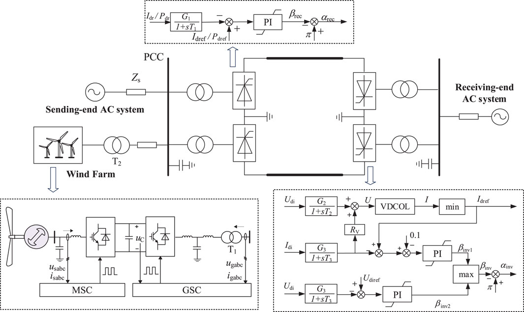
Figure 1. Structure of the LCC-HVDC system with wind power integration.
As shown in the above figure, the sending-end AC power grid consists of an equivalent AC system and a wind farm. The equivalent AC system represents the traditional synchronous power sources, and the wind farm is equivalently modeled as a single machine. Both equivalent AC system and wind farm are connected to the Point of Common Coupling (PCC). The LCC-HVDC adopts bipolar configuration with 12-pulse converter at both rectifier and inverter stations in each pole. The passive AC filters are configured at PCC for reactive power compensation and harmonic filtering. The receiving-end AC grid is modeled as an equivalent voltage source and an impedance.
In Figure 1, the wind farm consists of permanent magnet synchronous generator (PMSG) based wind turbines. The machine-side converter (MSC) adopts constant DC voltage control and maximum power point tracking (MPPT) control, while the grid-side converter (GSC) adopts constant active power control and constant reactive power control. The LCC rectifier station has two control modes: constant active power control and constant DC current control. The LCC inverter station adopts constant DC voltage control, equipped with a Voltage Dependent Current Order Limiter (VDCOL).
The main parameters of the LCC-HVDC system are shown in Table 1, and the main control parameters are shown in Table 2.
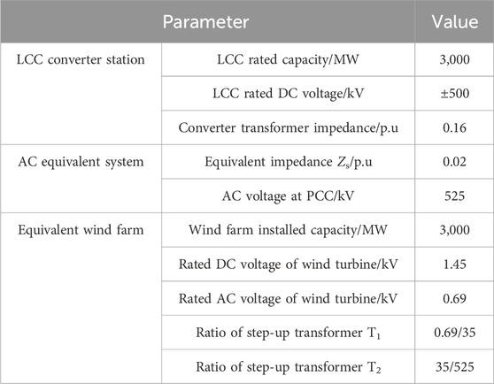
Table 1. The main parameters of the LCC-HVDC system with wind farm.
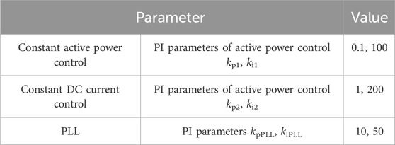
Table 2. Main control parameters of the LCC-HVDC system.
2.2 State-space models of LCC-HVDC system under different control strategies
2.2.1 Constant active power control
The constant active power control can ensure that the DC transmission power remains at a fixed value. The control block diagram is shown in Figure 2. The measured active power is filtered through a first-order filter and then compared with the given power reference. A proportional-integral controller with a saturation is used to generate the conduction angle, and further give the firing angle reference.

Figure 2. Block diagram of constant active power control.
From the above figure, the mathematical model of the constant active power control is given in Equation 1:
Where, Pdref and Pdr are the reference and measured values of active power respectively; kp1 and ki1 are the proportional gain and integral gain of the constant active power control respectively, and βmax and βmin are the maximum and minimum values of the conduction angle respectively.
Introduce an intermediate variable x1 as in Equation 2:
Then the generated firing angle reference can be expressed in Equation 3:
2.2.2 Constant DC current control
The constant DC current control strategy can ensure that the DC current remains at a fixed value. The control block diagram is similar to that of the constant active power control, as shown in Figure 3.
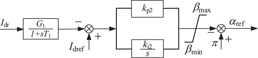
Figure 3. Block diagram of constant DC current control.
As shown in Figure 3, the mathematical model of the constant DC current control is given in Equation 4:
Where, Idref and Idr are the reference and measured value of the DC current respectively; kp2 and ki2 are the proportional and integral gain of the constant DC current control respectively, and βmax and βmin are the maximum and minimum values of the conduction angle respectively.
Introduce an intermediate variable x2 as in Equation 5:
Then the generated firing angle reference can be expressed in Equation 6:
2.2.3 State-space model
The LCC-HVDC system with wind power integration consists of two subsystems: the wind farm and the LCC-HVDC system. According to Tan et al. (2022), the state-space model of the wind farm composed of PMSG wind turbines can be expressed in Equation 7:
In the equation, XWT is the state vector, and UWT is the input vector of the wind turbine.
According to Guo et al. (2023), the state-space model of the LCC-HVDC subsystem can be expressed in Equation 8:
In the equation, XLCC is the state vector, and ULCC is the input vector of the LCC-HVDC subsystem. When the constant active power control is adopted, ULCC = Pdref; when the constant DC current control is adopted, ULCC = Idref.
Since the control systems of PMSG and LCC-HVDC are based on different dq rotating frames, it is necessary to establish an interface between the state-space models of each subsystem. The relative position of the dq rotating frames of the two subsystems, PMSG and LCC-HVDC, is shown in Figure 4.
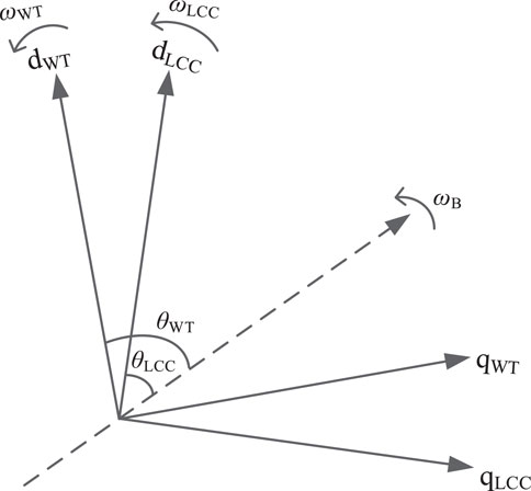
Figure 4. Relative position of the dq rotating frames of the two subsystems.
In Figure 4, the dashed line represents the synchronous rotating axis, with the rotational frequency equal to the rated angular frequency ωB. The frequencies and phase angles output by the PLLs of the PMSG and LCC-HVDC are represented by ωWT, θWT, and ωLCC, θLCC respectively. The conversion between two dq reference frames is shown in Equation 9.
Based on the models of the above two subsystems and the interface, the state-space model of the LCC-HVDC system with wind power integration can be expressed in Equation 10:
In the equation, X is the state vector, and U is the input vector of the overall system.
By linearizing the above state-space equations, the small-signal models of the LCC-HVDC system under different control strategies can be obtained, as shown in Equation 11.
In the equation, A is the state matrix, and B is the input matrix.
2.3 Small-signal stability analysis of LCC-HVDC system under different control strategies
Based on the small-signal model established in the previous section, this section carries out an eigenvalue analysis when the LCC converter operates with different control strategies and evaluates the influence of AC system impedance and output power of wind farm on the system stability, thus providing the stable operating range of different control strategies.
2.3.1 Stable operating range of constant active power control
When the LCC rectifier station adopts constant active power control, the output power of the renewable energy station remains unchanged at 0.25 pu (with respect to the renewable energy capacity of 3000 MW). By changing the equivalent impedance of AC system (Zs_r in below figure), the system root-locus is obtained as follows:
It can be seen from Figure 5 that when the equivalent impedance of AC system is increased, the root-locus moves to the right, indicating that the system stability margin is decreasing. When the equivalent impedance increases to 0.45pu, the real part of eigenvalue will become positive, and the system will experience small-signal instability with an oscillation frequency of 16.61 Hz. To verify the above results, a simulation model was built in PSCAD/EMTDC. The equivalent impedance of the AC system was gradually increased, and the simulation results are shown in Figure 6. It can be observed that when the equivalent impedance increases to 0.45 pu, the system becomes unstable with an oscillation frequency of 16.23 Hz, which is close to the oscillation frequency obtained from the eigenvalue analysis, verifying the accuracy of small-signal model.
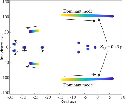
Figure 5. System root-locus when the equivalent impedance of AC system changes.
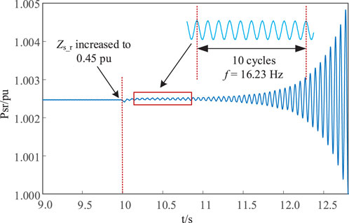
Figure 6. Active power Waveform when the equivalent impedance changes.
When the LCC rectifier station adopts constant active power control, the equivalent impedance of AC system is maintained at 0.33 pu. By changing the output power of the renewable energy station (P0 in below figure), the system root-locus is obtained as follows:
It can be seen from Figure 7 that when increasing the output power of the renewable energy station, the root-locus moves to the right, indicating that the system stability margin is decreasing. When the output power of renewable energy station reaches 0.39 pu, the real part of eigenvalue will become positive, and the system will experience small-signal instability.
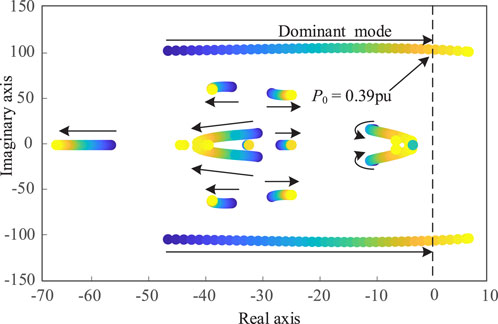
Figure 7. System root-locus when the output power of renewable energy changes.
2.3.2 Stable operating range of constant DC current control
When the LCC rectifier station adopts constant DC current control, the output power of the renewable energy station remains unchanged at 0.25 pu. By changing the equivalent impedance of AC system (Zs_r in below figure), the system root-locus is obtained as shown in Figure 8.
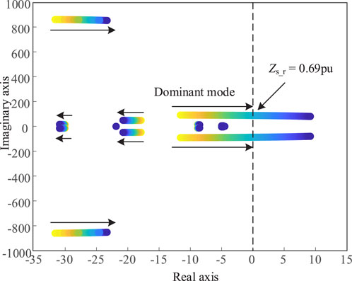
Figure 8. System root-locus when the equivalent impedance of AC system changes.
It can be seen from Figure 8 that when the equivalent impedance of AC system is increased, the root-locus moves to the right, indicating that the system stability margin is decreasing. When the equivalent impedance increases to 0.69 pu, the real part of eigenvalue will become positive, and the system will experience small-signal instability with an oscillation frequency of 13.95 Hz. To verify the above results, a simulation model was built in PSCAD/EMTDC. The equivalent impedance of the AC system was gradually increased, and the simulation results are shown in Figure 9. It can be observed that when the equivalent impedance increases to 0.69 pu, the system becomes unstable with an oscillation frequency of 13.56 Hz, which is close to the oscillation frequency obtained from the eigenvalue analysis, verifying the accuracy of small-signal model.
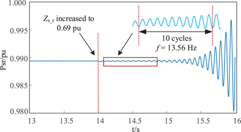
Figure 9. Active power waveform when the equivalent impedance changes.
When the LCC rectifier station adopts constant DC current control, the equivalent impedance of AC system is maintained at 0.33 pu. By changing the output power of the renewable energy station (P0 in below figure), the system root-locus is obtained as shown in Figure 10. It can be seen from Figure 10 that when increasing the output power of the renewable energy station, the root-locus moves to the right, indicating a decreased system stability margin. When the output power of renewable energy station reaches 0.46 pu, the real part of eigenvalue will become positive, indicating system instability.
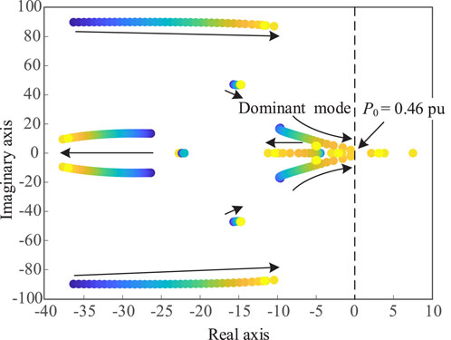
Figure 10. System root-locus when the output power of renewable energy changes.
Based on the above eigenvalue analysis of different control strategies, it can be concluded that when increasing the equivalent impedance of AC system or the output power of renewable energy, the system root-locus will move to the right, indicating a decreased system stability margin. Based on the eigenvalue analysis, the stable operating ranges of different control strategies have been obtained, which provides the control boundaries for the control switching in the next section.
3 Flexible control switching method for converter station in LCC-HVDC system
Due to the power intermittency and fluctuation, the large-scale integration of renewable energy into the grid inevitably leads to complex and variable operating conditions. A single control strategy is often insufficient to accommodate all operating scenarios. To maintain the stable operation of the system, it is essential to implement flexible control switching for converter station.
3.1 Flexible control switching principles
Based on the analysis in the previous section, the selection of control strategies should be adapted to the current operating conditions of the system. An inappropriate control strategy can directly exacerbate system instability. Considering the complex and variable system operating conditions, the flexible switching of control strategies has become a crucial approach to ensure the safe and stable operation of the LCC-HVDC system. Therefore, this paper proposes a flexible control switching method, with the main principles outlined as follows:
1) When switching control strategies, the primary principle is to ensure the stability of the system. When the system state changes, the original control strategy may no longer be applicable and need to be switched to a new one. The traditional direct switching method is often prone to cause instantaneous fluctuations that affect the power supply quality and even cause system failures, which is contrary to the original intention of control switching. Therefore, it is crucial to ensure that key electrical parameters, such as voltage and frequency, stay within safe and stable ranges during the control switching.
2) The switching of control strategies should ensure a smooth transition between different operating points, meaning that there should be no abrupt changes in the controller output during the control switching. The proposed flexible control switching method achieves this by real-time monitoring and synchronization of system parameters and control variables. Along with the original control, the backup control can dynamically adjust the required electrical quantities and the necessary inputs and intermediate variables for the control system, thus allowing a smooth transition of control strategies without introducing any sudden changes that could disrupt the system.
This flexible switching mechanism can not only ensure the continuity of system performance, but also flexibly respond to the needs of different system operating conditions.
3.2 Flexible control switching method
Based on the control switching principles introduced in the previous section, this section mainly presents the implementation of the flexible control switching method. For the LCC-HVDC system, the control strategies of the rectifier station generally include constant active power control and constant DC current control. From their control diagrams, it can be seen that the outputs of the two control strategies are both conduction angle/firing angle required by the rectifier. Therefore, only the input to the control link needs to be changed. The diagram of flexible control switching method is shown in Figure 11.
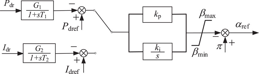
Figure 11. Diagram of flexible control switching.
Assuming that the converter station adopts constant active power control with constant DC current control on standby. The input of the active power control is the difference between the active power and the reference value, while the input of the standby control is the difference between the DC current and its reference value. Therefore, it is necessary to monitor the DC current in real time and synchronize it to the standby control. According to the monitored electrical quantity, the DC current reference is changed in real time so that the output of the PI controller is always zero before the control switching. When the control switching is activated, the controller does not introduce big error, thus ensuring a smoothly switching of the control strategies. After the control switching, the DC current reference can be adjusted to the given value gradually. Similarly, when the constant DC current control needs to be switched to constant active power control, the active power is monitored in real time to ensure a flexible switching of the control strategies. In this way, no matter how the system operating conditions change, the electrical quantity required for the standby control can be accurately tracked. If the original control strategy cannot operate stably under the change in the equivalent impedance of AC system or the output power of renewable energy, it can be switched to the new control stably and smoothly. The change of grid condition can be reflected by the equivalent grid impedance, which can be sensed by online grid impedance estimation techniques. With coordination of online grid impedance estimation, the flexible control switching method can be applied to effectively maintain the stable operation of LCC-HVDC system under different operating conditions, which is not discussed in this paper due to limited space.
4 Verification of flexible control switching method for LCC-HVDC system
Based on the analysis of the control boundaries for LCC converter stations in the previous section, a corresponding simulation model is built in PSCAD/EMTDC. The feasibility and effectiveness of the flexible control switching method for LCC-HVDC system are verified from two cases: change in the AC grid impedance and change in the output power of renewable energy.
Case 1: Verifying the feasibility and effectiveness of flexible control switching method when the AC equivalent impedance changes. The initial control strategy for LCC converter station is set to constant active power control. The AC grid impedance is increased to 0.45 pu at t = 10s. Based on the eigenvalue analysis in Figure 5, the LCC-HVDC system with constant active power control will become unstable. At t = 11s, the converter control is switched to constant DC current control. Figure 12 shows the simulated active power at PCC before and after the flexible control switching of the converter. When adopting constant active power control, the LCC rectifier is controlled to provide 1.0 pu DC power to the inverter side; while with constant DC current control, the DC current is controlled to 1.0 pu but the DC power at rectifier side is not exactly at 1.0 pu depending on the DC voltage at rectifier station. Thus, with constant active power control or constant DC current control, the LCC rectifier is at different operating conditions. The step-change in the active power in Figure 12 indicates the change of operating point before and after the control switching.
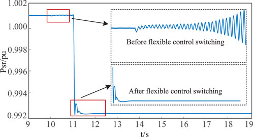
Figure 12. Simulation results before and after the flexible control switching.
As seen in the figure above, when the equivalent impedance of AC grid is changed to 0.45 pu at t = 10s, the LCC-HVDC system with constant active power control becomes unstable. At t = 11s when the converter control is switched to constant DC current control, the system gradually converges and eventually operates stably. Therefore, Case 1 demonstrates the feasibility and effectiveness of the flexible control switching method when the equivalent impedance of AC system changes.
Case 2: Verifying the feasibility and effectiveness of flexible control switching method when the output power of renewable energy changes. At t = 8s, the output power of the renewable energy station increases to 0.39 pu. Based on the eigenvalue analysis in Figure 7, the LCC-HVDC system with constant active power control will become unstable. At t = 9s, the converter control is switched to constant DC current control. Figure 13 shows the simulated active power at PCC before and after the flexible control switching of the converter.
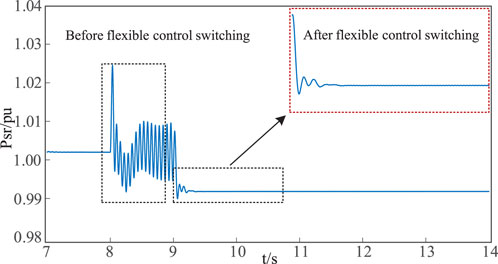
Figure 13. Simulation results before and after the flexible control switching.
As seen in the figure above, when the output power of the renewable energy station increases at t = 8s, the LCC-HVDC system with constant active power control becomes unstable. At t = 9s, when the converter control is switched to constant DC current control, the system gradually converges and eventually operates stably. Therefore, Case 2 verifies the feasibility and effectiveness of the flexible control switching method when the output power of the renewable energy changes.
5 Conclusion
In this paper, the state-space model of the LCC-HVDC system with renewable energy at the sending-end is established and the small-signal stability and stable operating range of the system under different control strategies are analyzed. Then, based on the designed control switching principles, a flexible control switching method applicable to the LCC-HVDC system is proposed. The main conclusions are as follows:
1) A single converter control strategy is difficult to adapt to all operating conditions, such as different AC grid strength or output power from renewable energy station, thus affecting the safety and stability of the LCC-HVDC system.
2) From small-signal analysis, the stable operating range of different control strategies in LCC converter station are compared and analyzed. Based on the obtained control boundaries, a flexible control switching method is proposed to enhance the stable operation of LCC-HVDC system under different operating conditions.
3) The simulation results show that the LCC converter can smoothly switch between different control strategies without imposing big disturbances to the overall system, proving the feasibility and effectiveness of the proposed flexible control switching method.
Data availability statement
The original contributions presented in the study are included in the article/supplementary material, further inquiries can be directed to the corresponding author.
Author contributions
MP: Writing–original draft. XH: Writing–original draft. RX: Writing–original draft. LF: Writing–review and editing. FL: Writing–review and editing. WJ: Writing–review and editing.
Funding
The author(s) declare that financial support was received for the research, authorship, and/or publication of this article. This work is supported by the Science and Technology Project of China Southern Power Grid EHV Power Transmission Company, China Southern Power Grid Joint Laboratory of DC transmission Equipment and Submarine Cable Safety Operation (Research on Identification of Short Circuit Capacity and Stability Control Technology of HVDC System, No. 0120002023030301SJ00078).
Conflict of interest
Authors MP, LF, and FL were employed by CSG EHV Power Transmission Company.
The authors declare that this study received funding from the Science and Technology Project of China Southern Power Grid EHV Power Transmission Company. The funder had the following involvement in the study: study design.
Generative AI statement
The author(s) declare that no Generative AI was used in the creation of this manuscript.
Publisher’s note
All claims expressed in this article are solely those of the authors and do not necessarily represent those of their affiliated organizations, or those of the publisher, the editors and the reviewers. Any product that may be evaluated in this article, or claim that may be made by its manufacturer, is not guaranteed or endorsed by the publisher.
References
Chen, W., Ye, Y., Zhou, B., Yang, J., Wang, J., and Fu, C. (2020). Influence of constant voltage control and predictive constant extinction angle control on small-signal stability of HVDC. Automation Electr. Power Syst. 44 (18), 98–111.
Cui, P., Guo, C., Jiang, W., and Zhao, C. (2020). Optimization of control parameters of LCC-HVDC system with STATCOM based on Lyapunov stability and Monte Carlo algorithm. Proc. CSEE 40 (12), 3858–3866. doi:10.13334/j.0258-8013.pcsee.190358
Guo, C., Jiang, W., Yin, Z., and Zhao, C. (2018). A supplementary damping coordination control for LCC-HVDC system with STATCOM under weak AC grid conditions. Proc. CSEE 38 (20), 5957–5964. doi:10.13334/j.0258-8013.pcsee.172179
Guo, C., Lü, N., and Zhang, J. (2023). Optimization of control parameters to enhance stability and dynamic performance of LCC-HVDC under weak AC condition. Trans. China Electrotech. Soc. 38 (07), 1751–1764. doi:10.19595/j.cnki.1000-6753.tces.211915
Guo, C., Zhao, J., Liu, W., and Zhao, C. (2019). A supplementary virtual-resistor damping control for hybrid multi-infeed HVDC system. Proc. CSEE 39 (12), 3400–3409. doi:10.13334/j.0258-8013.pcsee.180776
Hao, X., Guo, C., Jiang, W., Peng, M., and Lin, X. (2023). Identification method for equivalent impedance of AC power grid connected to MMC-HVDC system based on reactive power injection. Automation Electr. Power Syst. 47 (9), 184–192.
He, Y., Xiang, W., Zhao, J., Zhou, J., Lu, X., Ni, B., et al. (2021). A modified dynamic phasor model for small-signal stability analysis of LCC HVDC system. Power Syst. Technol. 45 (4), 1417–1428. doi:10.13335/j.1000-3673.pst.2020.0226
Liu, J., Wang, J., Ye, Y., and Wang, Z. (2024). Influence of different PLLs on stability of LCC-HVDC control loop. Power Syst. Technol. 48 (03), 1202–1217. doi:10.13335/j.1000-3673.pst.2023.0121
Liu, Z., Zhang, Q., Dong, C., Zhang, L., and Wang, Z. (2014). Efficient and security transmission of wind, photovoltaic and thermal power of large-scale energy resource bases through UHVDC projects. Proc. CSEE 34 (16), 2513–2522. doi:10.13334/j.0258-8013.pcsee
Mirsaeidi, S., Dong, X., Tzelepis, D., Mat Said, D., Dyśko, A., and Booth, C. (2019). A predictive control strategy for mitigation of commutation failure in LCC-based HVDC system. IEEE Trans. Power Electron. 42 (9), 160–172. doi:10.1109/TPEL.2018.2820152
Mo, Z., Wang, J., Ding, T., Liu, Y., Ye, Y., Wang, J., et al. (2022). LCC-HVDC impedance modeling and small disturbance stability analysis based on improved switching function. Power Syst. Technol. 46 (11), 4491–4505. doi:10.13335/j.1000-3673
Tan, S., Guo, C., and Du, D. (2022). Fidelity analysis and evaluation of subsynchronous oscillation mode characteristics of PMSG-based wind farm aggregation model. Proc. CSEE 42 (S1), 26–38. doi:10.13334/j.0258-8013.pcsee.221092
Yang, F., Xu, Z., and Zhang, J. (2006). Study on parameter optimization of HVDC PI controllers. Power Syst. Technol. (11), 15–20. doi:10.13335/j.1000-3673.pst.2006.11.005
Yu, F., Wang, X., Yang, Y., and Li, X. (2014). An application of hybrid genetic algorithm in the parameters optimization of HVDC constant current controller. Power Syst. Prot. Control 42 (9), 126–131.
Keywords: LCC-HVDC system, constant power control, constant current control, flexible switching method, renewable energy
Citation: Peng M, He X, Xiao R, Feng L, Liao F and Jiang W (2025) Flexible control switching method for converter station in LCC-HVDC transmission system. Front. Electron. 6:1558929. doi: 10.3389/felec.2025.1558929
Received: 11 January 2025; Accepted: 10 February 2025;
Published: 27 February 2025.
Edited by:
Wenjie Liu, Northwestern Polytechnical University, ChinaReviewed by:
Donghai Zhu, Huazhong University of Science and Technology, ChinaXiaoping Zhou, Hunan University, China
Yang Wang, Sichuan University, China
Copyright © 2025 Peng, He, Xiao, Feng, Liao and Jiang. This is an open-access article distributed under the terms of the Creative Commons Attribution License (CC BY). The use, distribution or reproduction in other forums is permitted, provided the original author(s) and the copyright owner(s) are credited and that the original publication in this journal is cited, in accordance with accepted academic practice. No use, distribution or reproduction is permitted which does not comply with these terms.
*Correspondence: Maolan Peng, cG1sMTA4MTE3MDkxMkAxNjMuY29t