 Gang Hu1,2
 Xuanhua Tian
 Pengchun Li
 Xi Liang
- 1Energy Resource School (State Key Laboratory of Oil and Gas Reservoir Geology and Exploitation), Chengdu University of Technology, Chengdu, China
- 2School of Petroleum Engineering (Engineering Technology Research Center of Guangdong Province for Unconventional Energy), Guangdong University of Petrochemical Technology, Maoming, China
- 3China Research Institute of Petroleum Exploration and Development of Shengli Oilfield, Sinopec Corp., Dongying, China
- 4Key Laboratory of Ocean and Marginal Sea Geology, South China Sea Institute of Oceanology, Chinese Academy of Sciences, Guangzhou, China
- 5Bartlett School of Sustainable Construction, University College London, London, United Kingdom
The geological storage of CO2 in offshore saline aquifers has been implemented at various sites worldwide. While subsea sediments can serve as a critical barrier against potential leakage from deep storage formations, the mechanisms and storage capacity for CO2 trapping within these sediments remain inadequately understood. This study developed a two-dimensional conceptual model of shallow sediments based on the Enping15–1 Carbon Capture and Storage (CCS) project site in the South China Sea. Furthermore, the CO2-water-rock reaction and storage mechanism were simulated using CMG-GEM, and the process of CO2 leakage into the sediments was investigated. The results indicate that CO2 leakage into the shallow seabed sediments is primarily sequestered through dissolution in pore water, accounting for 70% of the total sequestration, while residual and mineral trapping contribute 10–20%. The dissolution of CO2 leads to pore water acidification, which triggers the dissolution of anorthite and K-feldspar under the prevailing initial geochemical conditions. Dynamic reaction behavior is mainly observed at the leading edge of the acidified plume. However, if the leakage rate exceeds a critical threshold, the advancing acidified plume front causes partial dissolution of previously precipitated carbonate minerals. The critical leakage rate is determined to be 0.2 m³/day for single-point leakage and 0.3 m³/day for multi-point leakage. Notably, multi-point, low-velocity leakage enhances secondary storage within the sediment, thereby reducing the risk of CO2 release into the overlying seawater.
1 Introduction
The adverse consequences of global warming and climate change are presently escalating, with related impacts extending from social, economic and food security to the overall environment, including the living environment of the Earth (Li et al., 2023). Currently, Offshore Carbon Capture, Utilization, and Storage (OCCUS) technology has emerged as a central focus for coastal nations and regions seeking to develop new industrial value chains based on the sea. This constitutes an efficacious strategy for attaining reductions in carbon emissions (Li, 2025; Qin et al., 2023). In contrast to land-based storage, offshore CO2 storage sites typically situated at considerable distances from populated areas, lowering their impact on human life and health while exhibiting the advantage of low or no land occupation. Moreover, in addition to the seal of cap rock, the sedimentary layers and surface are likewise safeguarded by the pressure and barrier effects of seawater, greatly reducing the systemic risk of long-term storage (Mi, 2023; Qin et al., 2023). Especially, the near-surface sediments assume a pivotal role in the state and health of the marine environment as they convert, store and release chemical compounds (Figure 1). Laboratory experiments on sediment-CO2 reactions have exhibited mineral dissolution and metal release from aquifers and near-surface sediments as a result of desorption and pH reduction, with release of potentially harmful substances, such as toxic metals, into the benthic environment at low pH (Kirsch et al., 2014). However, the processes governing CO2 migration in near-seabed shallow sediments under more realistic CO2 leakage conditions are significantly more intricate than simulations in the laboratory due to tidal influences, specific seabed properties and the complex movement of the CO2 through the sediments, including lateral migration (Blackford et al., 2014; Cevatoglu et al., 2015). The nearshore in-situ CO2 release experiments conducted in shallow waters (STEMM-CCS) in the North Sea have shown that carbonate and silicate minerals reacted quickly with the dissolved CO2, increasing porewater alkalinity and neutralizing about 5% of the injected CO2. and the metals will also be released into porewaters. It also showed that the porewater composition and temperature are effective indicators for leakage detection, even at low CO2 leakage rates (Lichtschlag et al., 2021). However, the degree to which leaking CO2-rich fluids react under realistic conditions remains inadequately understood. A better understanding of the reactions of near-surface sediments with leaking CO2 is needed for the safe implementation of offshore geologic carbon storage and risk assessments and legislation.
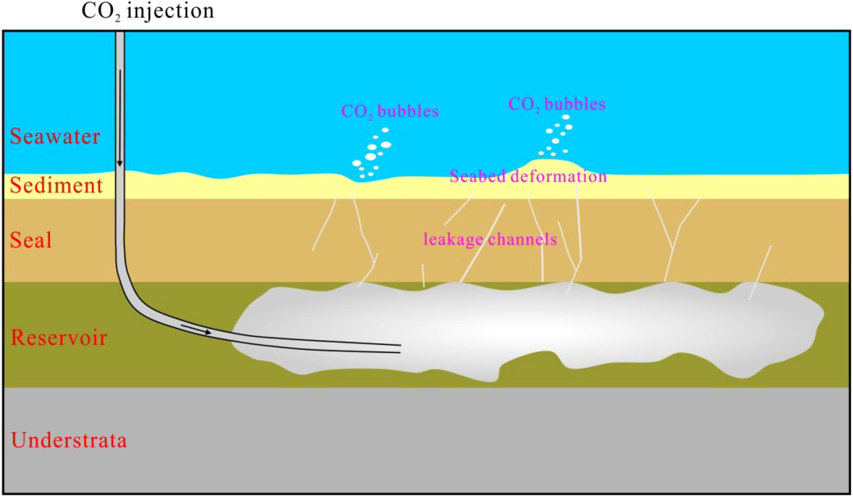
Figure 1. Schematic representation of marine environment effects above offshore CO2 geological storage site [modified according to Xiong et al. (2024)].
The offshore CO2 storage project at the Enping 15–1 oil field in the northern South China Sea, representing China’s inaugural offshore CCUS demonstration project, commenced production in June 2023, signifying the initiation of the demonstration phase for China’s offshore CCUS endeavors (Yi et al., 2023). The project is located in the Pearl River Mouth Basin, approximately 200 km southwest of Shenzhen, with an average water depth of approximately 90 meters. The saline aquifer for injection is situated at a depth of 820 meters below the seabed, and the project is expected to store approximately 300,000 tons of CO2 annually, with a cumulative storage total projected to exceed 14.6 million tons of CO2 over its operational lifetime (Zhao, 2023; Zhou et al., 2024). Furthermore, a joint research agreement for the development and operation of CCUS projects in the Daya Bay Area of China was signed in January 2023 by Shell, ExxonMobil, Guangdong DRC and CNOOC (Zhang et al., 2024). This agreement signifies the official commencement of collaborative research efforts for China’s pioneering offshore CCUS cluster demonstration project, which has a capacity of tens of millions of tons of CO2. The implementation of these projects will facilitate the rapid development of offshore CCS initiatives. However, research on the leakage risks and environmental impacts of CO2 geological storage in offshore China remains limited and requires further development. This paper employs the seabed sediments in the vicinity of the Enping 15–1 project as a case study to investigate the potential risks associated with CO2 leakage on the seabed sediment environment. This is accomplished through an examination of sedimentological characteristics and the modelling of the migration and chemical reactions of leaked CO2 within the sedimentary environment. This will facilitate a more comprehensive understanding of the environmental impact mechanisms of CO2 leakage, which holds substantial practical significance for guaranteeing the secure execution of subsea carbon storage.
2 Sediment compositions
Previous investigations have shown that the composition of seabed sediments in the northern region of the South China Sea is highly complex, consisting of a diverse array of materials. These materials include land-sourced debris, biogenic components, autochthonous minerals, volcanic debris, and various other elements. Surface sediment particles can be classified into four primary grain-size categories: gravel, sand, silt, and clay. Further categorization of surface sediment types includes gravel, coarse sand, medium sand, fine sand, silty sand, sandy silt, sand-clay mixtures, clay silt, silty clay, clay, and other types (Li et al., 2014). The sedimentary characteristics of shallow sediments, located at depths of 0 to 3 meters below the seafloor, indicate that they are predominantly composed of chalky sand and sandy silt. The fine sand and silt particles primarily consist of quartz, feldspar, and mica, along with a variety of heavy minerals, including ilmenite, pyrrhotite, zircon, rutile, and tourmaline. Clay minerals primarily include illite, montmorillonite, kaolinite, and chlorite. Sand grains constitute between 53.60% and 68.33% of the total mineral composition, while clay grains account for 10.97% to 16.33%. The carbonate mineral content averages approximately 14% (Gao et al., 2008; Li et al., 2014).
The Enping 15–1 Oilfield CO2 Storage Project is located in the shallow water shelf region of the Pearl River Mouth Basin in the northern South China Sea, approximately 200 km southwest of Shenzhen City. The mean water depth in this region is approximately 90 m (Yi et al., 2023). Based on seabed column sampling, sub-bottom profiling, as well as drilling and logging data, the shallow sediments at depths of up to 100 meters are primarily composed of fine sandy and muddy materials (Mei et al., 2020; Shang, 2023; Yi et al., 2023). The sedimentary structure consists of interbedded layers of fine sand and mud, exhibiting relatively stable lateral distribution, as illustrated in Figure 2. The seafloor sediments distributed in this area are primarily fine sandy muddy sediments, comprising an assemblage of clay minerals including illite, chlorite, montmorillonite and kaolinite. The detrital minerals are predominantly light minerals, including quartz, plagioclase feldspar, potassium feldspar, and other minerals such as hornblende, chloroclase, tourmaline, magnetite, ilmenite, sillimanite, apatite, and pyroxene analogs (Li et al., 2014). The proportion of sandy detrital particles ranges from 53.6 to 68.33%, while clay particles constitute between 10.97 and 16.33% of the total (Zhu et al., 2017). These sediments are largely dominated by clay minerals, with the highest clay mineral content comprising illite (43.8% to 49.3%), montmorillonite (26.7% to 35.7%), kaolinite (13.2% to 25.1%), and chlorite (3.7% to 9.6%). The chemical composition is primarily composed of SiO2, Al2O3, CaO, and Fe2O3, which together can account for up to approximately 90% of the total composition. Additionally, trace amounts of K2O, Na2O, MgO, P2O5, and TiO2 are present. The porosity of the sediments ranges from 48.82% to 66.2%, while their density varies from 1.6 to 1.84 g/cm³. Water saturation levels are high, ranging from 54.98% to 72.13%. The compressibility is notable, with a compression coefficient ranging from 1.26 to 2.26 MPa-¹ and a cohesion range of 5 to 15 kPa (Niu, 1992).
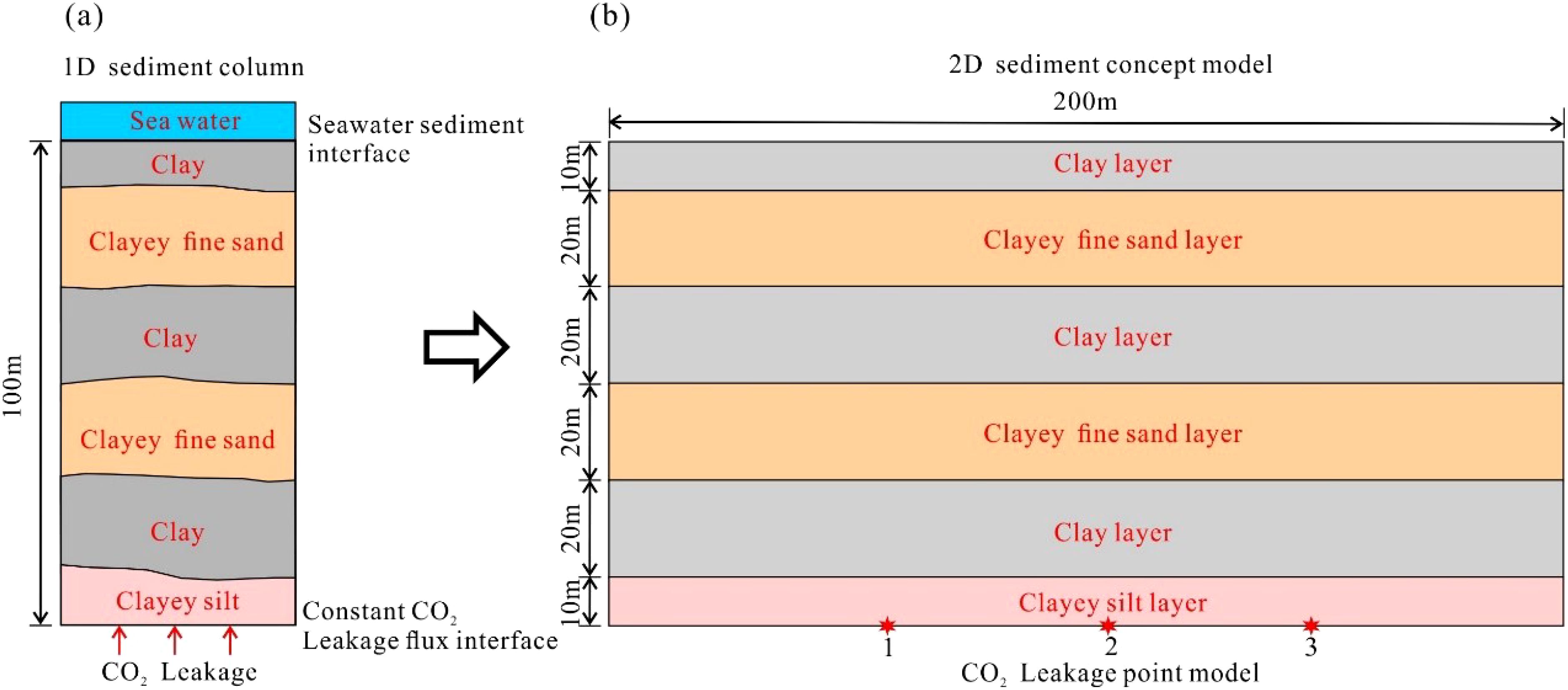
Figure 2. 1D column diagram (a) of the seabed shallow sediments based on offshore CO2 injection site of South China sea and 2D concept layer model (b) for CO2 leakage simulation.
3 Methodology
To enhance our understanding of the transport and geochemical reaction processes involved in CO2 leakage into seafloor sediments, this simulation focuses on the development characteristics of shallow sediments in the area surrounding the offshore CO2 storage project at the Enping 15–1 oilfield. This approach aligns with the findings of previous studies, which highlighted the importance of seafloor sediment characteristics in understanding these processes. Consequently, a two-dimensional conceptual similarity model has been developed to analyze and simulate the dynamics of CO2 transport and the kinetic processes of mineral dissolution and precipitation within the sediments, utilizing numerical simulation methods. The numerical simulation employs CMG-GEM software, a leading tool in reservoir simulation technology that has recently enhanced its capabilities for carbon sequestration research and development. To date, CMG-GEM has been adopted by over 600 companies and research institutions across more than 60 countries. This software utilizes the Peng-Robinson and Soave-Redlich-Kwong equations of state to calculate phase equilibrium compositions, allowing for accurate simulations of seepage and geochemical processes, including mineral precipitation, dissolution, and transport, in the context of CO2–water–rock interactions (CMG, 2023).
3.1 Model description
To investigate the effect of CO2 leakage in the seafloor sediment layer, we based our model on the sediment layer structure revealed by on-site drilling and logging data. The top surface of the model, which includes the seawater transition zone, is set at a depth of 10 meters. The sediment layer is defined as 80 meters thick, consisting of muddy sediment beneath the seafloor surface. Above this, a turbidite sand layer of 10 meters in thickness is included, with a horizontal well established at the base of the layer to simulate leakage fluxes. In order to simulate the leakage of CO2 into the sediment layer, a low-velocity injection of horizontal wells is employed at the bottom of the model. The depth of the water at the site is 100 meters, and the seafloor temperature of the seafloor is 5 degrees Celsius. Accordingly, the horizontal length of the 2D model is defined as 200 m, divided into 100 grids of 2 m each, while the vertical direction extends to 100 m, comprising 50 grids of 2 m each. This results in a total of 5–000 grids within the model (Figure 3).
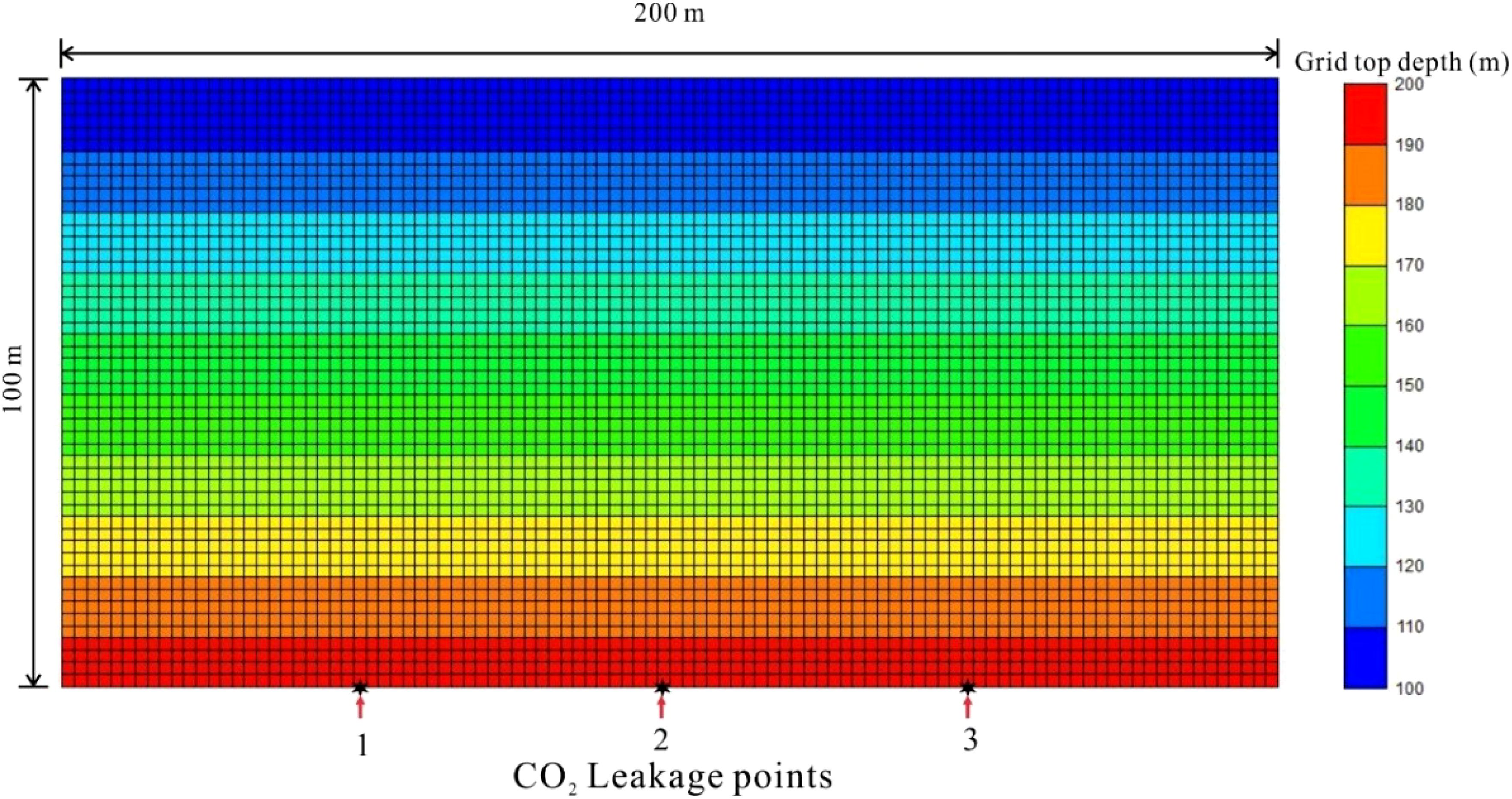
Figure 3. A 2D grid layer model showing grid tops and position of operating leakage points for CO2 leakage process simulation.
The sedimentary layers can be classified into three main categories: clay, fine-grained sand, and turbidite silt. Given the minimal variation in the seafloor sedimentary environment within the 200-meter range, the lateral distribution of the sediment layers is stable, and the heterogeneity is limited. Therefore, for simplification, each layer is treated as a homogeneous unit in the model. The mean characteristics of these three sedimentary units are detailed in Table 1. The initial conditions of the model are consistent with the hydrostatic pressure gradient, with a pressure of 1.96 MPa at a depth of 200 m (in the target leakage point zone). In the seabed sedimentary system, the unit is filled with sea water, which gives a saturation value of Sw = 1.
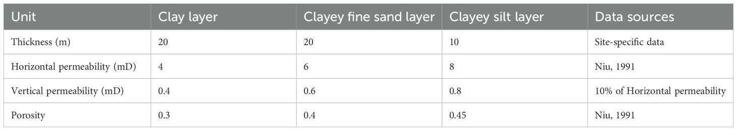
Table 1. Properties of sedimental units in the leakage Model.
3.2 Fluid properties and CO2 solubility
The CMG-Winprop software was utilized to determine the properties of the sedimentary fluid. The fluid compositional model comprises CO2 and CH4, with the Peng-Robinson equation of state employed to calculate the fluid properties. In the event of leakage, the CO2 will experience mainly residual, solubility and mineral trapping, given the critical point of carbon dioxide (critical pressure 7.376 MPa, critical temperature 31.05°C) versus the initial conditions of the seabed sediments layers (100 m water depth). The solubility of CO2 in the sedimentary pore water is dependent upon pressure and temperature. This is expressed by the Henry’s law correlation, which is a commonly used method for describing the solubility of gases in liquids at low and moderate partial pressures (Harvey, 1996).
3.3 Initial compositions
The principal minerals of the seabed sediments in the target zone are composed of clay and clastic minerals. The primary clay minerals identified were illite, kaolinite and smectite, with respective volume fractions of 9%, 9.7% and 3.7%. The clastic minerals identified include quartz, K-feldspar and anorthite, with respective volume fractions of 30%, 3.7% and 22.3%. The precipitate minerals resulting from the CO2 mineralization reaction may include ankerite, calcite, magnesite and siderite. The probability of these minerals forming is dependent on the relative abundance of the primary minerals present in the sediments, the dissolution rate and the thermodynamic stability of the carbonate minerals. In light of the aforementioned findings, calcite, dolomite, dawsonite, magnesite and siderite were identified as secondary minerals on the basis of the ions formed by the dissolution of the primary mineral and the reaction equations. The initial compositions of the sediments are presented in Tables 2 and 3. The highest concentrations of ions in the sedimentary pore water are observed for sodium, chloride, magnesium, calcium and bicarbonate.
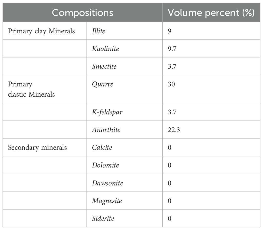
Table 2. Initial mineral compositions of sediments and pore waters in the model.
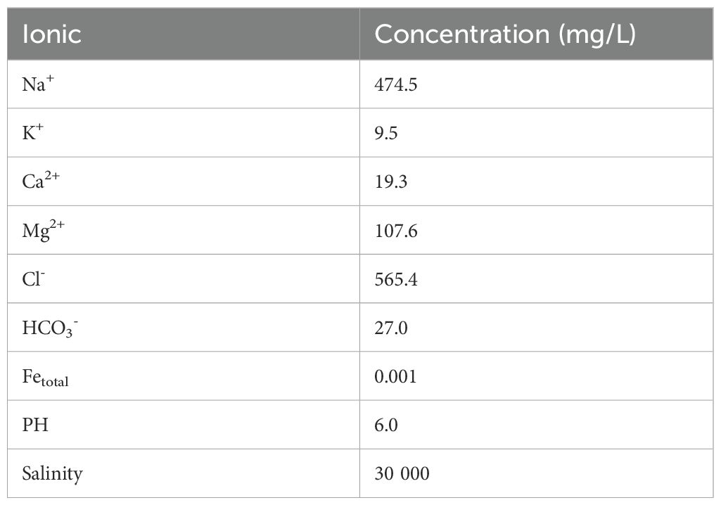
Table 3. Initial pore water compositions of sedimental layer in the model.
3.4 Mineral dissolution and precipitation reactions
Chemical reactions occur between minerals and aqueous components, referred to as heterogeneous reactions, as well as among components within the aqueous phase, known as homogeneous reactions. This includes gaseous components, such as dissolved CO2, as well as substances that exist solely in the aqueous phase. Typically, intra-aqueous reactions are characterized as chemical equilibrium reactions due to their relatively fast rates compared to mineral dissolution and precipitation reactions, which are described as rate-dependent processes. Below, we present the relevant equations utilized in this model, which have been implemented in CMG-GEM.
The aqueous chemical equilibrium reactions are as follows:
The mineral reactions considered in this study are as follows:
The rate law for the mineral dissolution and precipitation reaction is dictated by the composition and pH as the mineral reaction rate model given by (Bethke, 1996) is:
where rj is the reaction rate, is the reactive surface area for mineral j, kj is the rate constant of mineral reaction j, Keq,j is the chemical equilibrium constant for mineral reaction j, and Qj is the activity product of mineral reaction j. The activity product Qj is analogous to the activity product for aqueous chemical equilibrium reactions. The chemical equilibrium constants Keq,j for many minerals are also available in the literature (Bethke, 1996; Kharaka et al., 1988). The ratio (Qj/Keq,j) is called the saturation index of the reaction. If (Qj/Keq,j) > 1, mineral dissolution occurs in the system, if (Qj/Keq,j)< 1, mineral precipitation occurs (Nghiem et al., 2004). The simulator calculates the reaction rate constant (kj) at the reservoir temperature from its known value at a reference temperature T0 (T0 = 25°C) (CMG, 2023). The reactive surface area is another important parameter in the calculation of the rate. The following equation is used to calculate the reactive surface area with change in the moles of minerals through dissolution or precipitation:
where is the reactive surface area at time T0, Nj is the mole number of mineral j per unit grid block volume at current time and is the mole number of mineral j per unit grid block bulk volume at time T0.
The kinetic parameters of the mineral reactions considered in this study are presented in Table 4. The reactive surface areas of the reactants and the activation energies at the formation temperature are obtained from the Wolery database (Wolery, 2013). The corresponding reaction rates and reactive surface areas are calculated using Equation 1 and Equation 2, respectively.
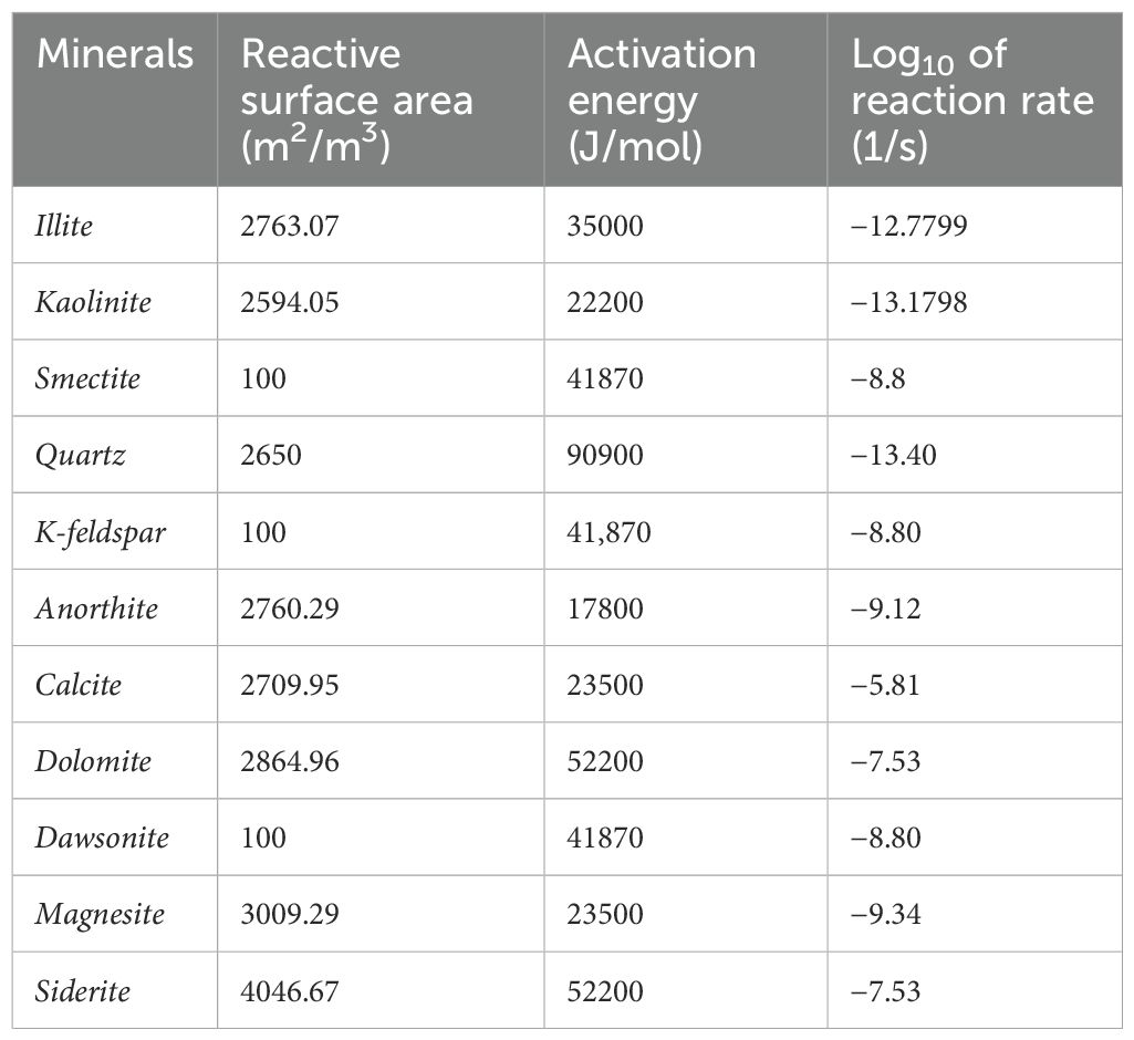
Table 4. Kinetic parameters of mineral reactions [adapted from Wolery (2013)].
3.5 Simulation scenarios
In this study, the fault leakage method simulates CO2 leakage through low-rate injection from a horizontal well at the bottom of the simulation. The locations of the leakage points are indicated at the bottom of Figure 3, specifically at points 1, 2, and 3. The simulation encompasses both single-point and multi-point leakage scenarios. To assess the mineralization reaction and long-term stability, the simulation duration is set to 100 years, allowing for the observation and analysis of the interactions between CO2 and the sedimentary layer under varying leakage rates and locations. Given the low leakage rate considered, which is unlikely to cause significant changes in seafloor stress, mechanical effects are not included in this study.
For the 2D simulation of the leakage scenario, the leakage rate is established at 0.005 to 0.5 m³/d, based on natural submarine gas leakage, particularly the typical flux of submarine natural gas and seepage, which ranges from 0.081 to 4.050 mmol·C/day/m². Two leakage modes are examined: single-point leakage and multi-point leakage. The cases evaluated in this study are summarized in Table 4 and illustrated in Figure 3. As detailed in Table 5, these cases involve either one or three leakage points, as depicted in Figure 3. In the single-point leakage simulation, point 2 serves as the leakage point, with a leakage rate of 0.005 to 0.3 m³/d. In the multi-point leakage simulation, leakage points 1, 2, and 3, as shown in Figure 3, have a range of leakage rates from 0.005 to 0.5 m³/d.
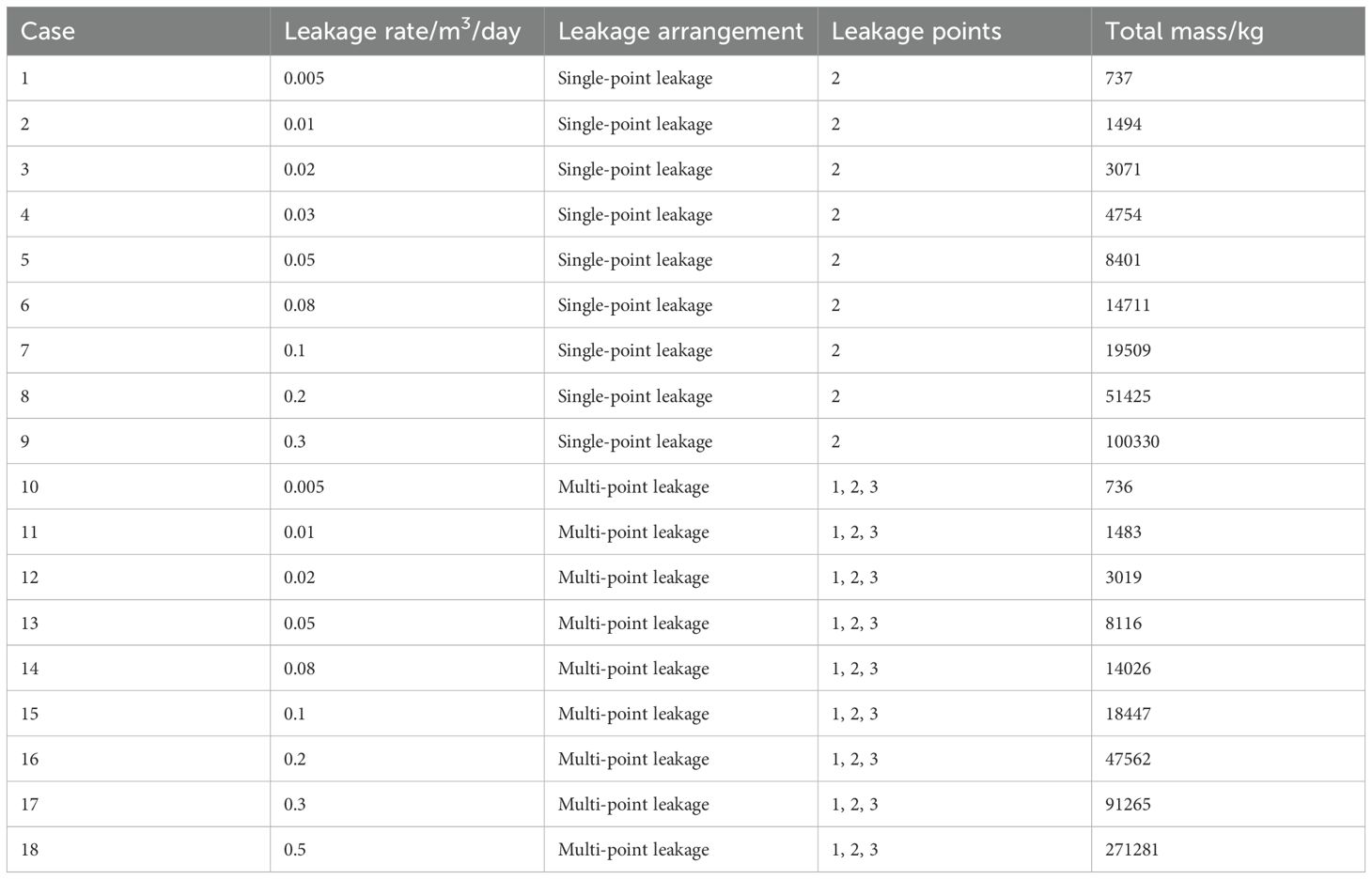
Table 5. List of cases in the model.
In line with the conventional timeline for carbon capture, utilization, and storage (CCUS) projects, the leakage simulation period is set at 10 years, assuming that leakage occurs at the midpoint of the project. An additional 100-year simulation will be conducted to facilitate a more detailed examination of mineral dynamics and the long-term conditions of the seeped CO2. This approach enables a comprehensive consideration of the dynamic and long-term conditions of seeped CO2.
4 Results and analysis
4.1 Single-point leakage
Figure 4 illustrates the cumulative leakage CO2 and the variations in the amounts of dissolved CO2, trapped CO2, and mineralized CO2 within the target sediments over a 100-year period under different single-point scenario rates. The profiles indicate that during the initial 10-year leakage phase, the CO2 rapidly dissolves into the sedimentary pore water. Following this phase, the rate of CO2 dissolution slows and transitions into a nearly linear increase over time. The initial dissolution rate during the leakage phase is associated with the convective transport of CO2 into the sediments, which enhances the interfacial contact area between the CO2 gas phase and the aqueous phase, thereby accelerating the dissolution process (Figure 4). Once the leakage ceases, the lack of convective movement in the gas phase means that diffusive transport of CO2 from the surrounding area becomes the primary process. Consequently, during this phase, the interfacial area no longer expands, leading to a reduction in the concentration of dissolved CO2 in the pore water surrounding sediments. This results in the nearly linear profiles observed in Figure 4 after year 10. However, at higher leakage rates, as shown in Figure 4a, the dissolution curve exhibits a slight decline between 40–50 years, which may be attributed to increased mineralization and bound sequestration.
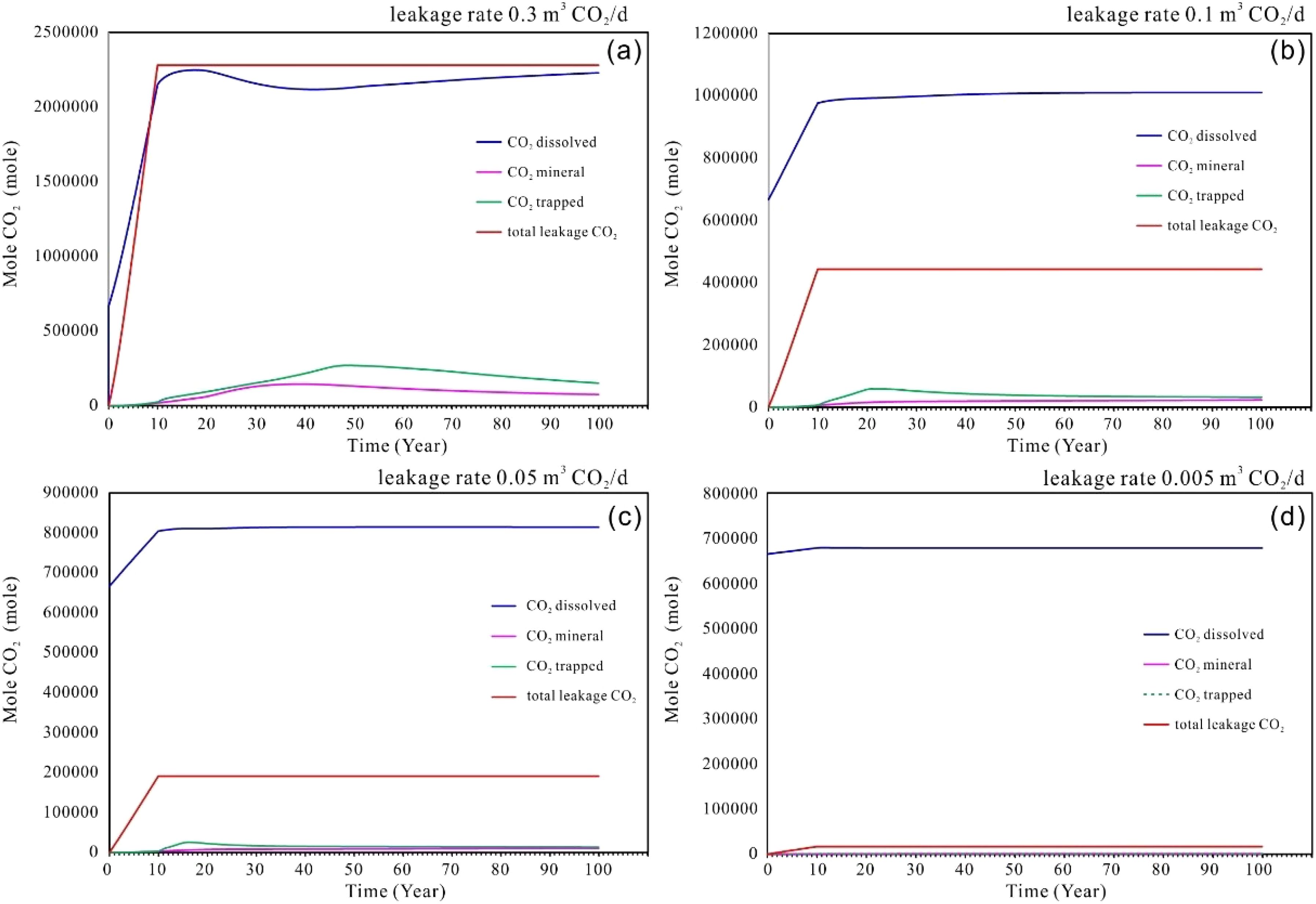
Figure 4. (a–d) Cumulative amounts of CO2 leakage into the seabed shallow sediments, dissolved CO2, trapped CO2 and mineral CO2 at different leakage rate of single point scenarios.
In addition to the dissolved CO2 within the system, a proportion of the total volume can be attributed to residual trapping and mineralized CO2. However, the proportion of residual and mineralized CO2 vary according to the mount of CO2 released. As the leakage rate increases, the volumes of residual and mineralized CO2 also rise proportionally. However, the total volume of residual trapping CO2 exceeds that of mineralized CO2 when considered collectively. As depicted in Figure 4, at minimal leakage rate (e.g., 0.005-0.05 m³/day), the contributions of mineralized CO2 and residual trapping CO2 are negligible. Conversely, at higher leakage rate, (e.g., 0.1~0.3 m³/day), mineralization becomes evident, with all samples showing an upward trend during the 20–40 years following the leakage event. This trend reaches a maximum content, after which a slight decline occurs, followed by a period of relative stability. This indicates that mineralized forms of CO2 remain stable over the long term, once dissolution and sedimentation have achieved equilibrium.
As leaked CO2 is primarily in a dissolved state, its dissolution in the aqueous phase leads to the production of hydrogen ions (H+) and bicarbonate ions (HCO3−). This process causes the acidification of sediment pore water and a decrease in the pH of the aqueous phase. Figure 5 illustrates the temporal evolution of pH distributions within the sediment layer of the seabed formation. The changes in pH distribution correspond to the movement of the CO2 leakage point within the sediment. The initial pH of the sediment pore water was recorded at 6.0. Subsequently, the dissolution of CO2 within the sediment produces carbonic acid, which dissociates into hydrogen and bicarbonate ions, resulting in a decrease in pH to approximately 4.4 in the pore water of the CO2 leakage area. This area, which has a flame-like shape, propagates upwards during a leak, as illustrated in Figure 5a. After the leakage ceases, the buoyancy-driven movement of CO2 within the system allows the pH distribution to continue evolving upwards within the sediment. After 17 years, the pH value at the surface approaches that of the seafloor. However, as the pH gradually reaches equilibrium, the pH pattern elongates, and the value decreases to 4.6-5.2 (Figure 5b). Eventually, the pH values stabilize, reaching approximately 5.4 (Figures 5c, d).
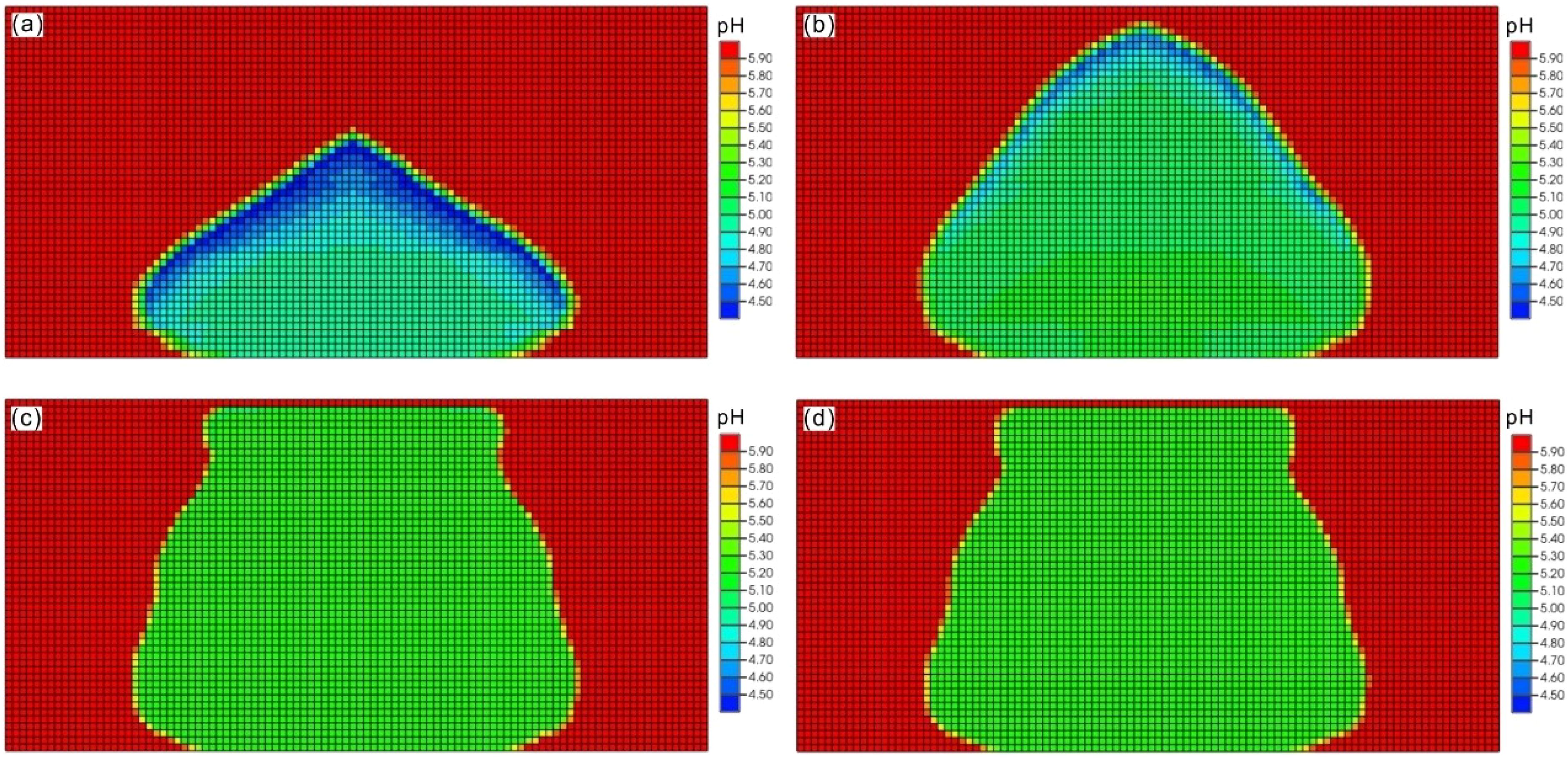
Figure 5. The model results of developments of pH plume in the seabed shallow sediments up to time of 100 years after CO2 leakage in single point scenario with rate of 0.3 m3/day. (a) time of 10 years; (b) time of 17 years; (c) time of 50 years (d) time of 100 years.
The observed increase in pH following the cessation of leakage can be attributed to mineralogical reactions and the influx of aquifer water (at its original pH) into the CO2-affected region. As CO2 dissolves in the water, which results in a reduction of gas-phase saturation and a replacement of the dissolved volume with external water from outside the flame area. The initial mineral composition of the sediment (predominantly quartz and anorthite, as outlined in Table 2) and the initial ion species content dissolved in the sediment water (detailed in Table 3) lead to the dissolution of the anorthite due to acidification, as illustrated in Figure 6. The precipitated minerals include primarily calcite and dawsonite, followed by dolomite, potassium feldspar, siderite, and kaolinite. However, at a higher leakage rate (e.g. 0.3 m³/day), as shown in Figure 6a, the subsequent mineralization reaction becomes more intense, and the dissolution of dolomite and siderite is also evident. In contrast, the initial decrease in smectite is followed by an increase, indicating that smectite is also a significant mineral for long-term carbon fixation. Other minerals, such as quartz, magnesite, and illite, exhibit relatively stable behavior with minimal variation.
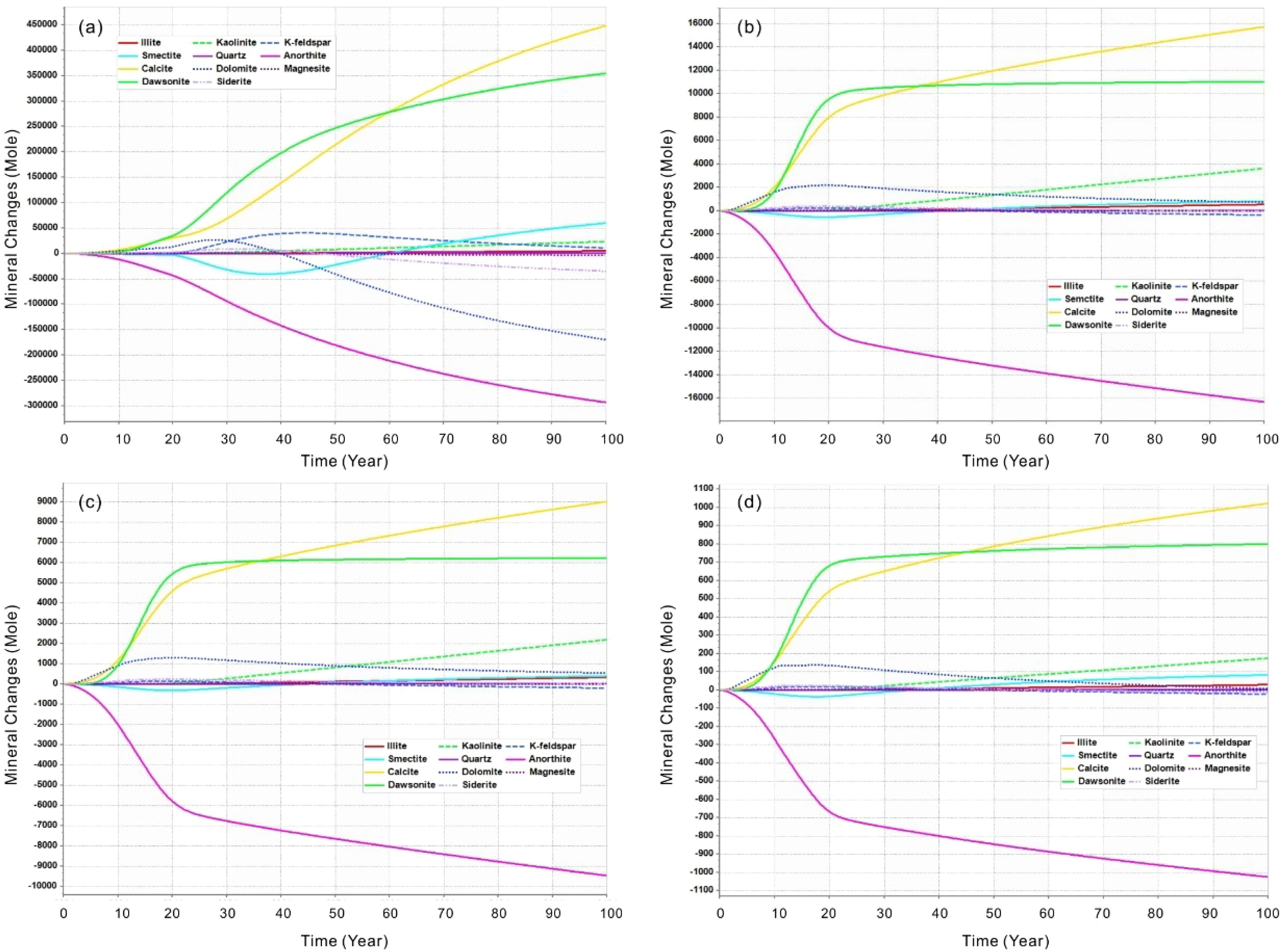
Figure 6. Mineral molar changes (positive is precipitation and negative is dissolution) of minerals in the seabed shallow sediments over time after CO2 leakage at different rate of single point scenarios. (a) Leakage rate of 0.3 m3/day; (b) Leakage rate of 0.1 m3/day; (c) Leakage rate of 0.05 m3/day; (d) Leakage rate of 0.005 m3/day.
4.2 Multi-point leakage
The extension of the leak point to three locations, with two additional leak points situated on either side of the single point of leakage, represents a scenario typical of multiple point leakages. The leakage rates for each point are comparable to those observed in the single point leakage cases, as documented in Table 4. Figure 7 illustrates the cumulative leakage of CO2 and the change in the quantities of dissolved CO2, trapped CO2, and mineral CO2 within the target sediments over a 100-year period under scenarios involving multiple leak points with varying rates.
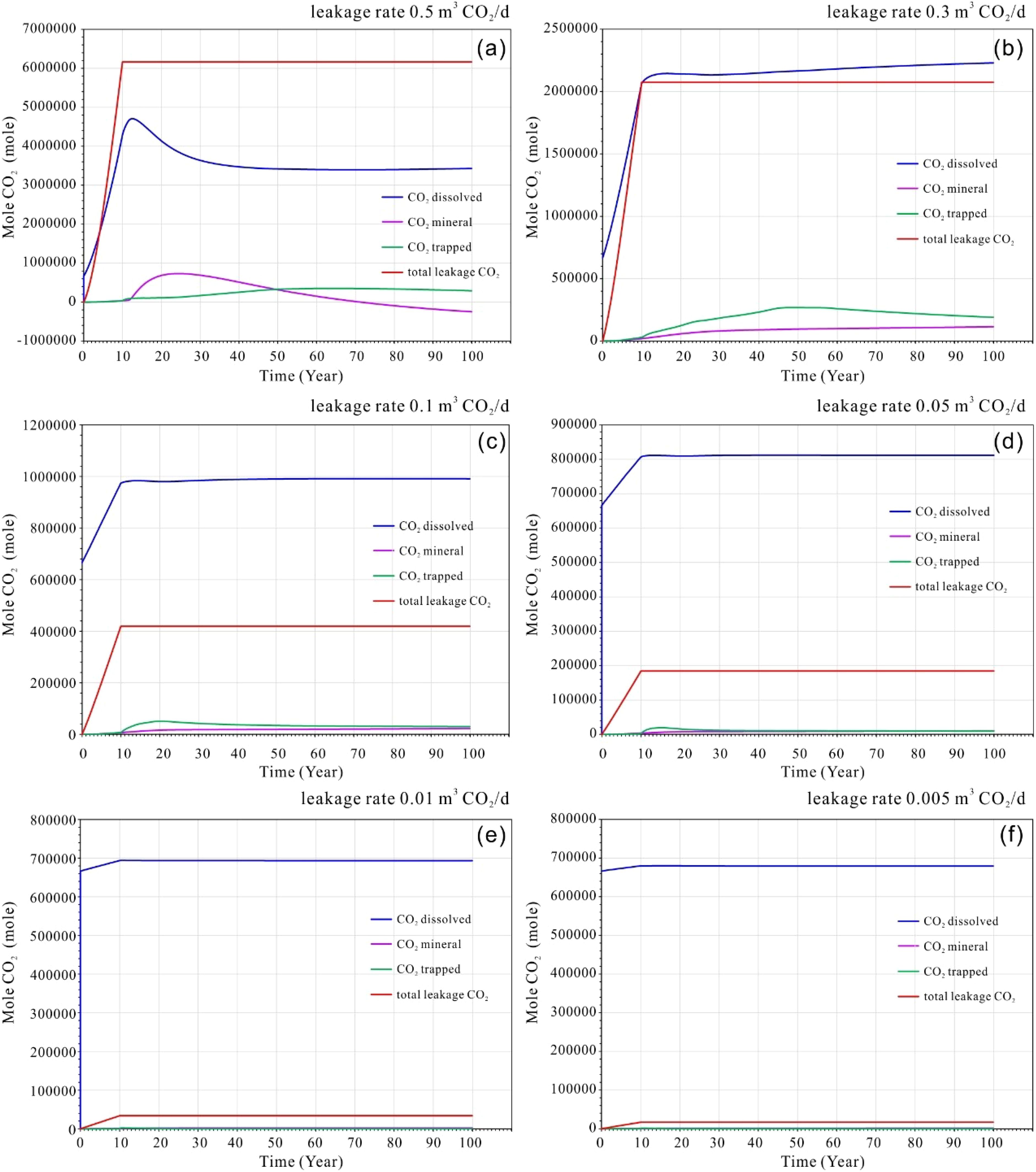
Figure 7. (a–f) Cumulative amounts of CO2 leakage into the seabed shallow sediments, dissolved CO2, trapped CO2 and mineral CO2 at different leakage rate of multi-points scenarios.
Similar to the single point leakage case, the profiles indicate that during the initial leakage stage (the first 10 years), CO2 from the multi-point leakage is predominantly in a dissolved state. The quantity of CO2 released increases linearly with the duration of the leakage period. As shown in Figures 7a, b, at higher leakage rates, the dissolved CO2 continued to rise even after the cessation of leakage, reaching a maximum within two to three years post-cessation. However, a slight decrease in dissolved CO2 was observed in the subsequent years, likely attributable to the effects of mineral and residual trapping (Figures 7a, b).
In contrast, for low-rate leakage scenarios, the dissolution of CO2 peaked after the leak ceased and remained relatively constant thereafter (Figures 7c, f). The trapping of CO2 in minerals and residual materials was more pronounced at higher rates, as illustrated in Figures 7c, d. This suggests that mineral and residual trapping of CO2 became more significant following the cessation of leakage. Furthermore, the mineral CO2 displayed a pattern of initial increase followed by a decrease, indicating that the rise in leakage volume led to transitional phase of acidification. This process resulted in the re-dissolution of minerals, a phenomenon that should consideration in the context of seafloor environments experiencing significant disturbances.
For higher leakage rates, as shown in Figures 7a, b, the maximum residual trapping of CO2 occurred with a corresponding delay of 50 to 60 years, which may be related to the continuous diffusion of CO2 within the sedimentary layers. In contrast, at lower leakage rates, residual trapping of CO2 reached its maximum within approximately 10 to 20 years and remains essentially unchanged thereafter (see Figures 7c, d).
In the multi-point leakage approach, the CO2 that leakage is dissolved in water, leading to a change in pH levels. Consistent with the single-point leakage method, a leakage rate of 0.3 m³/day is employed as an example to illustrate the process of pH alteration. It is evident that the dissolution of CO2 leads to a decrease in the pH of the pore water within the sedimentary layer. The overall pH distribution can be characterized by three flame-like plum shapes, with the central leakage point serving as the axis of symmetry, while the left and right sides are symmetrical. As shown in Figure 8, the pH plum at the central leakage point is narrower. During the leakage phase, the pH value decreased due to the release of CO2, reaching a minimum of 4.4. After the leakage stopped, the pH plume continued to rise, eventually reaching a value of 5.4. This pattern remained relatively stable for nearly 50 years, with only a slight decline in pH that did not reach the seafloor. This indicates that a significant distance remains before this occurs. Consequently, it can be inferred that the leakage to the seafloor is incomplete, with the released CO2 being sequestered within the sediment layer.
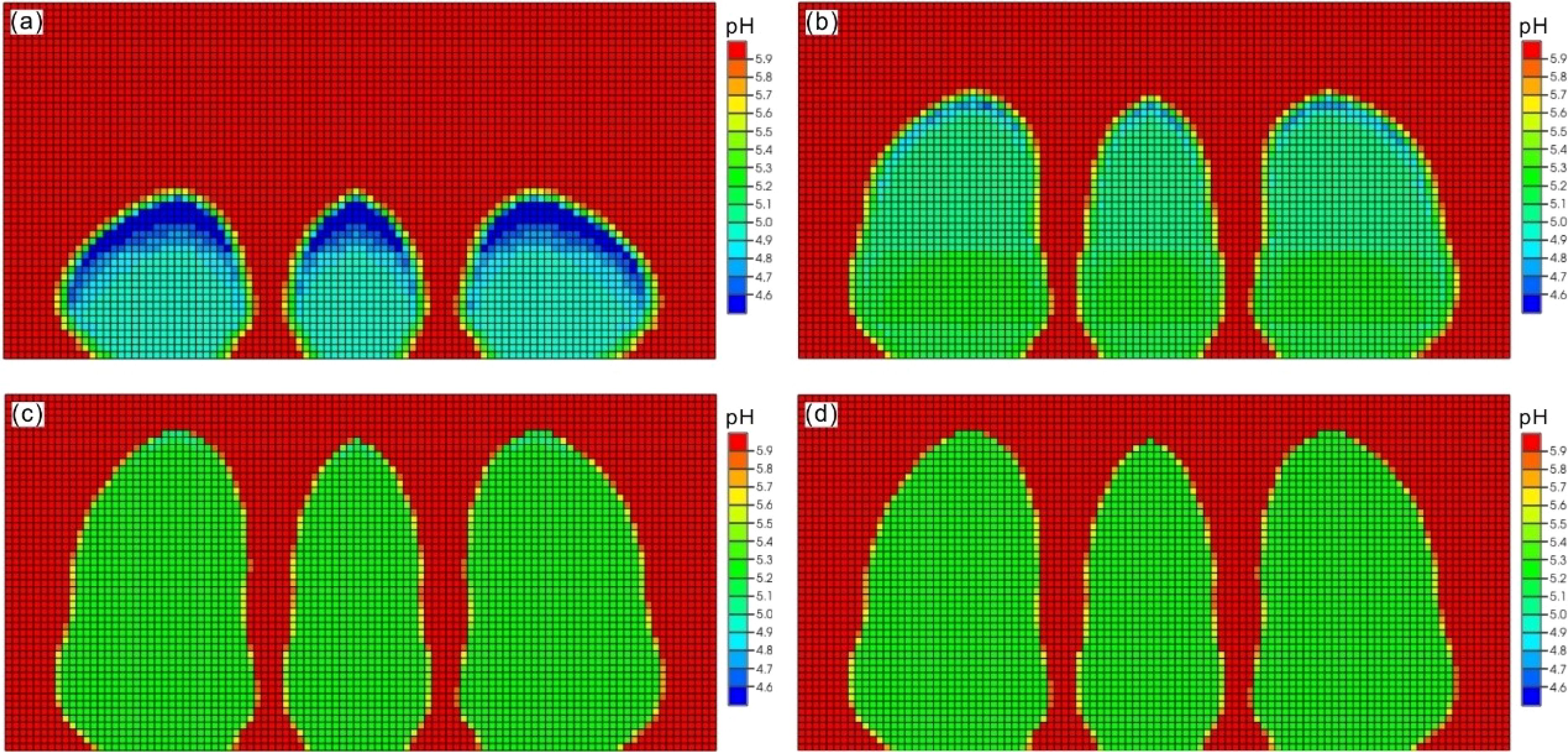
Figure 8. The model results of developments of pH plume in the seabed shallow sediments up to time of 100 years after CO2 leakage in multi-points scenario with rate of 0.3 m3/day. (a) time of 10 years; (b) time of 20 years; (c) time of 50 years (d) time of 100 years.
In the multi-point leakage model, mineral dissolution and the precipitation of new minerals occur as a result of the pH reduction caused by the dissolved CO2. As shown in Figure 9, the dissolved minerals are primarily anorthite, while the precipitated minerals are predominantly calcite and dawsonite. Additionally, dolomite and kaolinite are noteworthy precipitated minerals, particularly at lower leakage rate (<0.3 m³/day), where dolomite is more susceptible to reduction through late dissolution (Figures 9b-f). This phenomenon is particularly pronounced at higher leakage rate as shown in Figure 9a, where the vulnerability of dolomite and siderite becomes evident. Smectite undergoes dissolution followed by re-precipitation, with dissolution generally occurring approximately 30–40 years prior to leakage, accompanied by a gradual increase in its content.
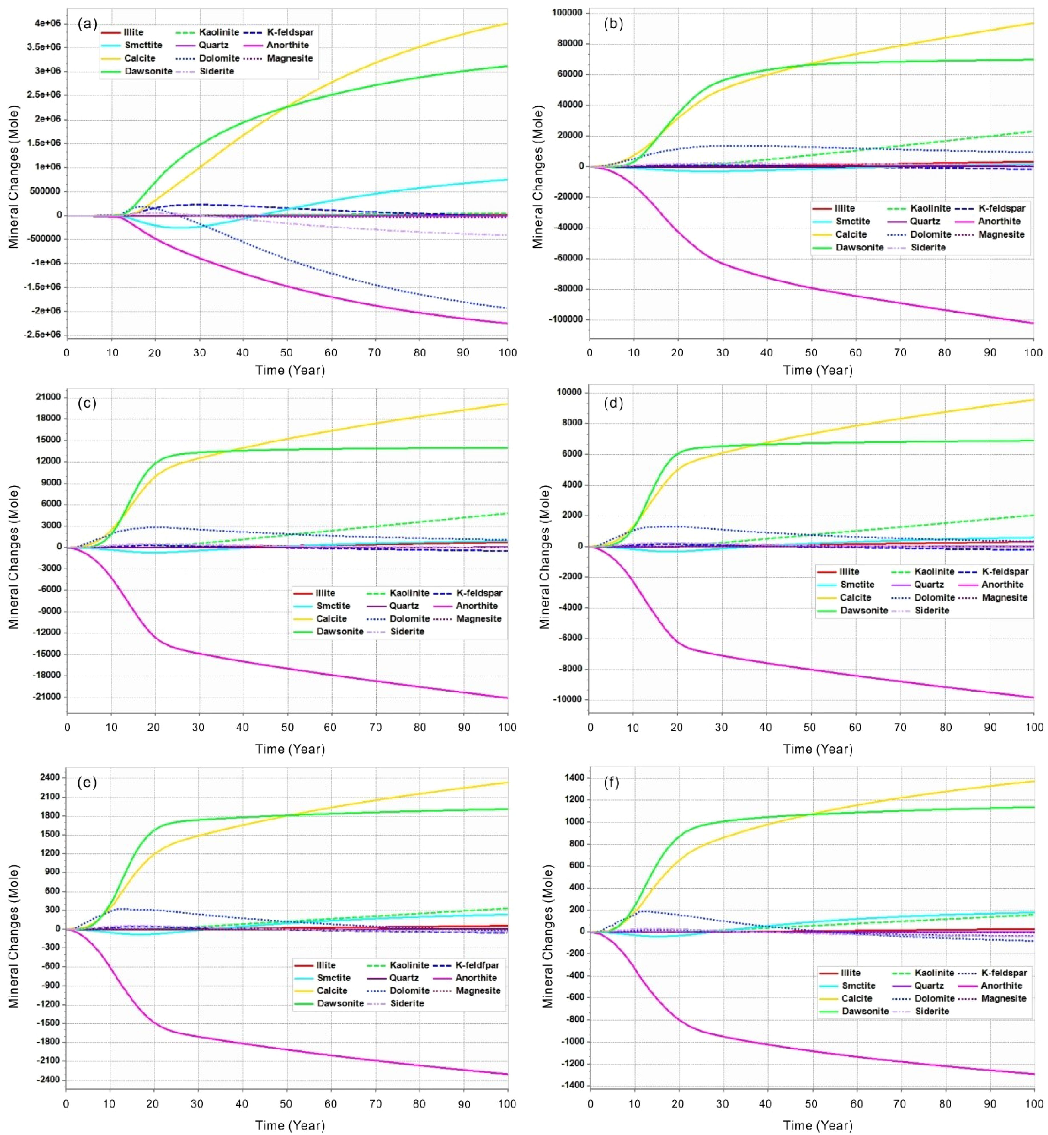
Figure 9. The mineral molar changes (positive is precipitation and negative is dissolution) of minerals within the seabed shallow sediments over time after CO2 leakage at different rate of multi-point scenarios. (a) Leakage rate of 0.5 m3/day; (b) Leakage rate of 0.3 m3/day; (c) Leakage rate of 0.1 m3/day; (d) Leakage rate of 0.05 m3/day; (e) Leakage rate of 0.01 m3/day; (f) Leakage rate of 0.005 m3/day.
Furthermore, this process also contributes to long-term carbon fixation. The concentration of K-feldspar initially increases before subsequently declining. As shown in Figure 9a, at higher leakage rates, the magnitude of this change is amplified. In contrast, the composition of other detrital minerals, such as quartz and illite, exhibits minimal fluctuations.
5 Discussions
5.1 Sediment CO2 storage mechanism and risk assessment
The modeled CO2 leakage depth of 200 meters below the seafloor is inadequate to achieve supercritical pressure conditions, which is consistent with findings from previous studies, including Lab experiments, the natural CO2 migration through geoformations into the ocean and designed filed experiments in conjunction with offshore CO2 storage research (Li et al., 2020; Lichtschlag et al., 2021; Lukawska-Matuszewska et al., 2023; Uemura et al., 2011; Zhao et al., 2024). Consequently, the leaked CO2 is released primarily in a gaseous form. Our simulations indicate that even minor CO2 leaks are rapidly absorbed by pore water within the sedimentary layer. This is consistent with previous research suggesting that dissolution is the predominant process governing shallow subsurface CO2 migration (Ardelan et al., 2012; Borrero-Santiago et al., 2016; Dean et al., 2020). This behavior remains consistent regardless of the leakage configuration—whether single-point or multi-point—with dissolved CO2 constituting 68.54–80.59% of total storage. This significantly exceeds mineral storage (3.29–7.04%) and residual trapped CO2 (~9.16%) (Figures 10, 11). These proportions are broadly comparable to findings from laboratory-scale experiments (Ardelan et al., 2012; Blackford et al., 2020; Gholami et al., 2021; Lichtschlag et al., 2021; Lukawska-Matuszewska et al., 2023). However, our higher dissolution rates may reflect the impact of sediment heterogeneity in natural systems.
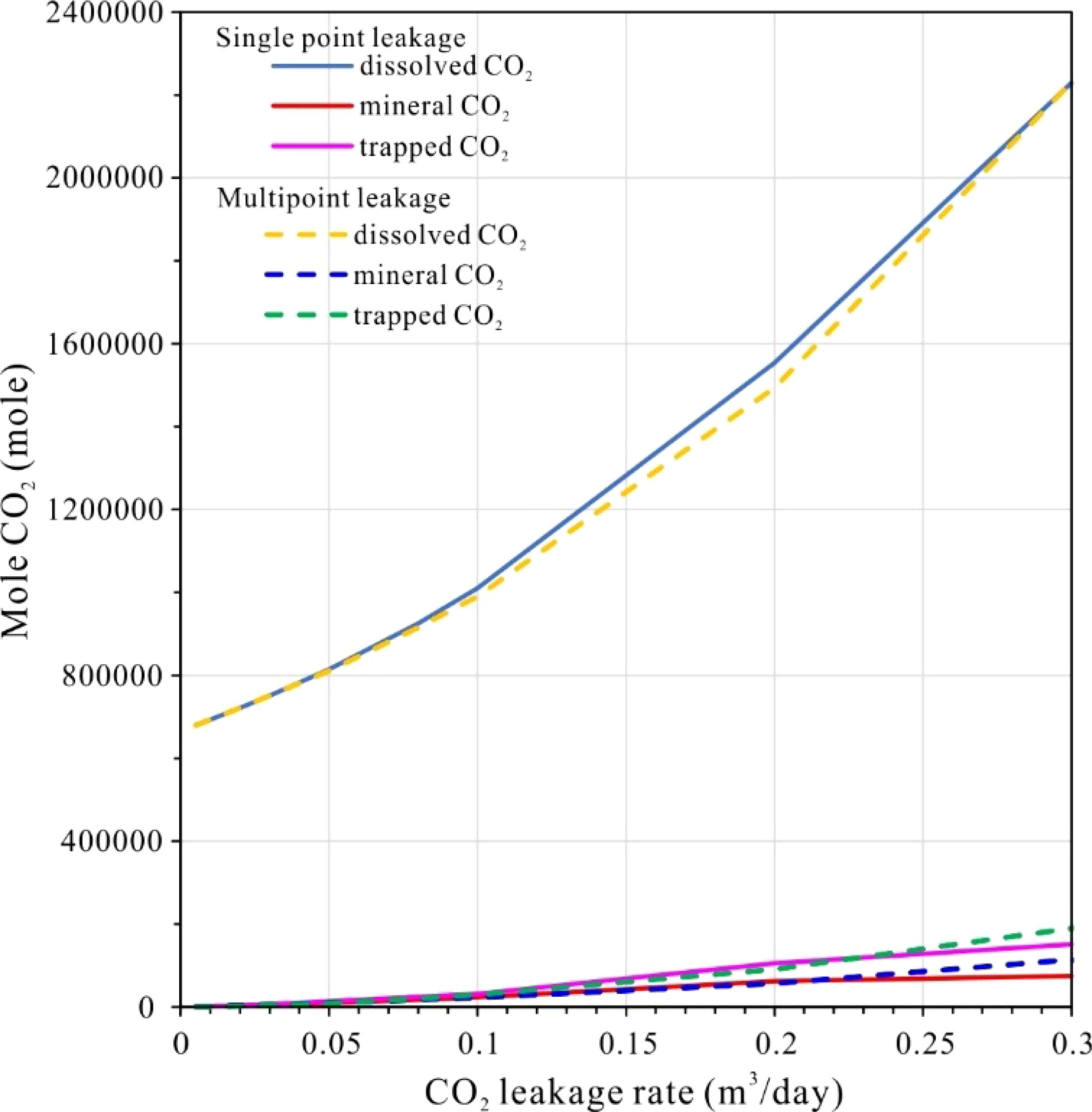
Figure 10. Cumulative amounts of dissolved CO2, trapped CO2 and mineral CO2 at different leakage model.
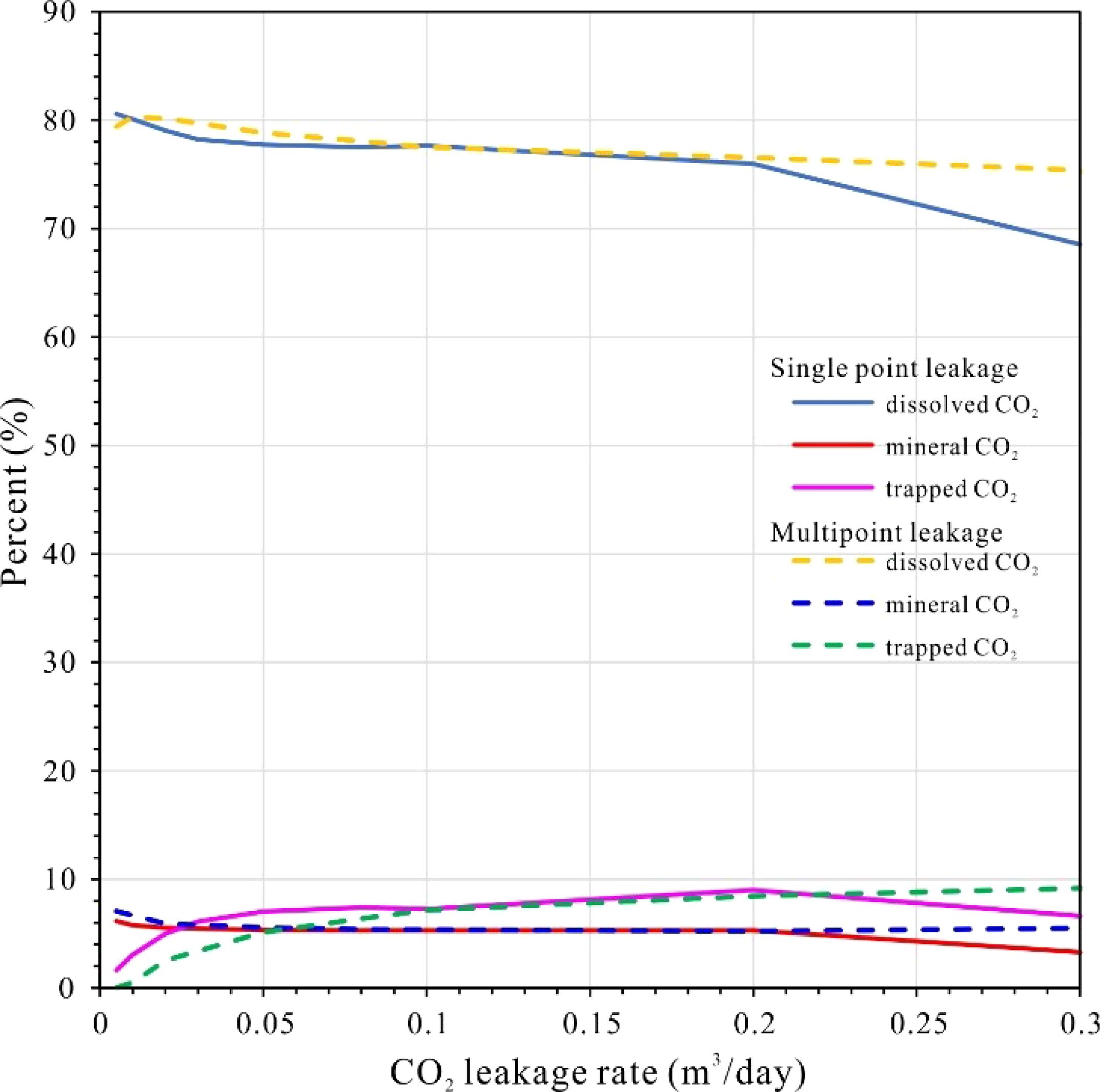
Figure 11. The percents of dissolved CO2, trapped CO2 and mineral CO2 at different leakage model.
Importantly, all storage mechanisms—dissolution, mineralization, and residual trapping—exhibit rate-dependent increases with higher leakage fluxes, although their growth rates vary, dissolution accelerates most rapidly, followed by residual trapping, while mineralization progresses at a slower pace. This pattern contrasts with studies of deeper reservoirs, where CO2 mineralization typically dominates at higher pressures (Jin et al., 2016; Ranganathan et al., 2011; Rezk and Ibrahim, 2025). Multi-point leakage further modifies these dynamics, resulting in a more rapid accumulation of trapped and mineralized CO2, while the dissolution rate is slower compared to single-point leakage. This distinction may be attributed to enhanced fluid dispersion, as hypothesized by prior CO2 release experiment studies (Blackford et al., 2020; Hoffman et al., 2021; Lichtschlag et al., 2021; Zhang et al., 2024).
As leakage rates increase, the proportion of dissolved CO2 gradually decreases, while the fractions of trapped and mineralized CO2 rise. A critical threshold is observed at 0.2 m³/day, beyond which the curves for single-point leakage decline sharply (Figure 11), indicating a breakthrough of gaseous CO2 into seawater. This observation is consistent with theoretical predictions regarding low-porosity sediments, where the dissolution kinetics are insufficient to counteract advective fluxes (Ardelan et al., 2012; Lichtschlag et al., 2021; Lukawska-Matuszewska et al., 2023). In contrast, multi-point leakage extends the allowable range of leakage before breakthrough occurs, suggesting that distributed injection strategies could mitigate seepage risks. This practical insight is supported by field-scale simulations (Saleem et al., 2021; Shang, 2023).
5.2 Sediment CO2 mineral reactions
The dissolution of leaked CO2 into sediment porewater generates hydrogen ions (H+) and bicarbonate (HCO3-), lowering pH and driving acidification—a process well-documented in both natural and experimental systems (Lichtschlag et al., 2021; Saleem et al., 2021). This acidification promotes silicate mineral dissolution, as evidenced by increased porewater concentrations of Si, Mg, Fe and Ca in field experiments, consistent with observations from natural CO2-rich sediments near Japan (de Beer et al., 2013) and laboratory studies (Mickler et al., 2013). Importantly, silicate dissolution rates in our system are consistent with prior findings indicating that they are generally slower than carbonate reactions (Brantley et al., 2008). Nevertheless, our data suggest CO2-induced weathering remains a non-negligible process, particularly for aluminosilicates like anorthite and K-feldspar (Figure 12).
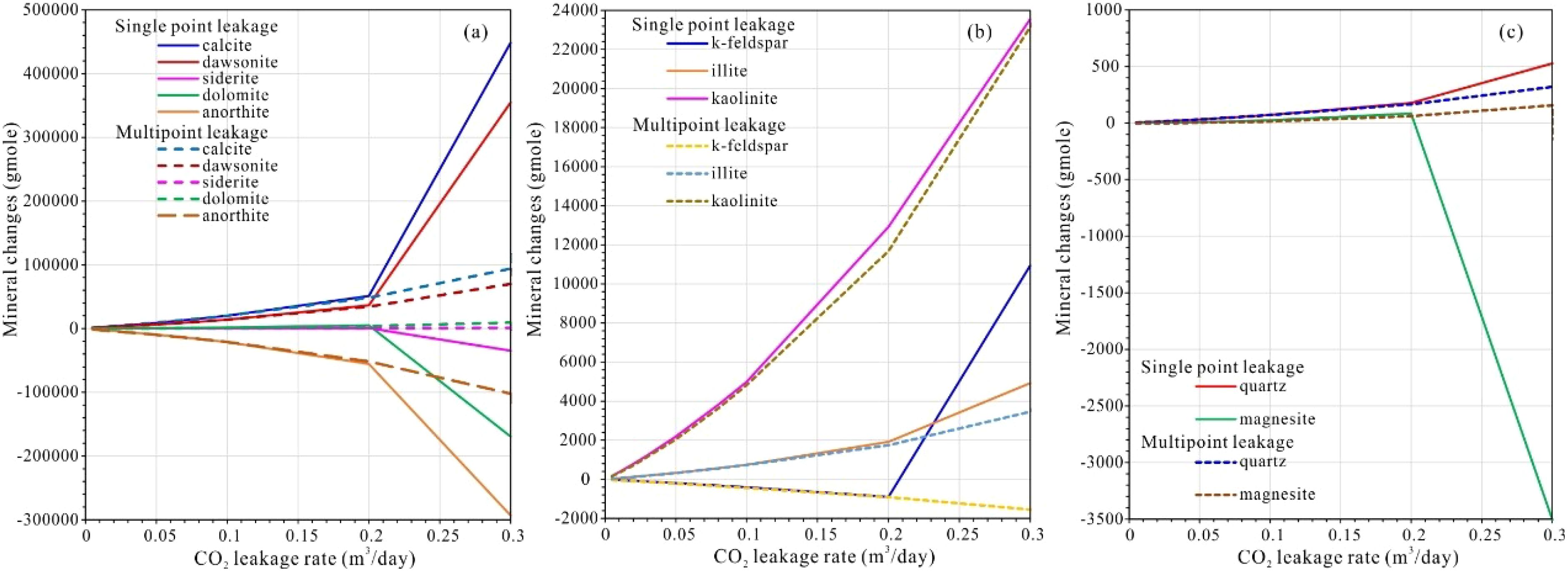
Figure 12. (a–c) Comparison of mineral mole changes of minerals in entire sediments versus CO2 leakage rate in single and multiple scenarios (positive is precipitation and negative is dissolution).
Model results demonstrate that silicate dissolution releases cations (e.g., Ca²+, Mg²+, Fe²+), which then react with bicarbonate to precipitate secondary carbonates (calcite, dolomite, siderite, magnesite) and clay minerals (kaolinite, illite). While calcite dominates the precipitate assemblage—mirroring observations in analog CCS leakage sites (Dean et al., 2020)—dawsonite formation is also significant, a contrast to some laboratory studies where its stability is limited (Borrero-Santiago et al., 2016; Saleem et al., 2021; Yodpetch et al., 2025). Quartz precipitation remains minimal, likely due to kinetic inhibitions under low-temperature seabed conditions (Rezk and Ibrahim, 2025; Zhao et al., 2024).
Despite continuous mineral reprecipitation near the plume front, net accumulation is limited because subsequent acidification dissolves earlier-formed phases (e.g., dolomite, magnesite) as the plume advances. This dynamic equilibrium echoes experimental findings, where cyclic dissolution-precipitation occurred under fluctuating CO2 fluxes (Shang, 2023; Yodpetch et al., 2025). Leakage rate strongly modulates these reactions: beyond thresholds of 0.2 m³/d (single-point) or 0.3 m³/d (multi-point), rapid dissolution of metastable carbonates (dolomite > siderite > magnesite) outweighs precipitation (Figure 12), compromising sediment stabilization—a risk similarly noted in column experiments (Lichtschlag et al., 2021; Lukawska-Matuszewska et al., 2023; Saleem et al., 2021).
Critically, at lower leakage rates (<0.2 m³/d), single- and multi-point scenarios yield nearly identical mineral reaction volumes, suggesting that leakage configuration becomes irrelevant if fluxes remain subdued. However, multi-point leakage exhibits greater resilience to higher fluxes, delaying carbonate dissolution thresholds. This aligns with theoretical models suggesting that the distributed leakage mitigates localized mineral instability by dispersing acidification impacts (Lichtschlag et al., 2021; Saleem et al., 2021). Thus, while minor leaks pose minimal geochemical disturbance, operational safeguards should enforce flux thresholds below 0.2 m³/d to prevent irreversible sediment acidification.
6 Conclusions
This study investigates the potential reactions that may occur in the event of CO2 leakage in an offshore seabed composed of K-feldspar and quartz sedimentary layers. Consideration the initial conditions of the minerals present in the sediments, the dissolved ions in the sedimentary water, and the pH, we can infer that CO2 leakage into these seabed sediments primarily involves solubility and residual trapping mechanisms. The acidification of the sedimentary pore water leads to the dissolution of anorthite and K-feldspar, resulting in the formation of a small amount of silica and clay.
An intriguing phenomenon occurs in the vicinity of the CO2 dissolved plume, where divalent cations in the sediment water react with bicarbonate to form carbonates. However, if the acidification exceeds a certain threshold, a portion of the carbonate will redissolve. These findings suggest that the seabed sediment may sever as a viable candidate for CO2 storage. The storage process is characterized primarily by dissolution, mineralization and trapping, with dissolution trapping accounting over 70% of the total, while mineralization and residual trapping contribute an additional 10-20%. This process enables long-term, permanent storage, thereby mitigating the risk of leakage.
In scenarios involving lower leakage rates, the overall storage effectiveness of multipoint leakage is comparable to that of single-point leakage. However, the multipoint leakage method can accommodate larger leakage rates. Consequently, the seabed sediment layer is more effective at absorbing small-scale multipoint leakage, further reducing the risk of leakage into the seabed.
Data availability statement
The original contributions presented in the study are included in the article/supplementary material. Further inquiries can be directed to the corresponding author/s.
Author contributions
GH: Conceptualization, Funding acquisition, Investigation, Methodology, Resources, Validation, Writing – original draft. XY: Supervision, Writing – review & editing. XT: Data curation, Formal Analysis, Funding acquisition, Project administration, Writing – review & editing. RW: Validation, Visualization, Writing – review & editing. PL: Methodology, Software, Writing – review & editing. LP: Validation, Visualization, Writing – review & editing. XL: Supervision, Visualization, Writing – review & editing.
Funding
The author(s) declare that financial support was received for the research and/or publication of this article. This work is financially supported by the Natural Science Foundation of Guangdong Province, China (No. 2018A030313433, 2024A1515013178), Innovation Team of Ordinary Universities in Guangdong Province-Oil and Gas Resources Exploration and Development Innovation Team (No. 2022KCXTD018), and the Scientific Research Start-up Project Fund of Guangdong University of Petrochemical Technology (No. 518170).
Conflict of interest
Authors RW was/were employed by Sinopec Corp.
The remaining authors declare that the research was conducted in the absence of any commercial or financial relationships that could be construed as a potential conflict of interest.
Generative AI statement
The author(s) declare that no Generative AI was used in the creation of this manuscript.
Publisher’s note
All claims expressed in this article are solely those of the authors and do not necessarily represent those of their affiliated organizations, or those of the publisher, the editors and the reviewers. Any product that may be evaluated in this article, or claim that may be made by its manufacturer, is not guaranteed or endorsed by the publisher.
References
Ardelan M. V., Sundeng K., Slinde G. A., Gjøsund N. S., Nordtug T., Olsen A. J., et al. (2012). Impacts of possible CO2 seepage from sub-seabed storage on trace elements mobility and bacterial distribution at sediment-water interface. Energy Proc. 23, 449–461. doi: 10.1016/j.egypro.2012.06.047
Bethke C. M. (1996). Geochemical reaction modeling: concepts and applications (New York, USA: Oxford University Press). Available online at: https://sc.panda985.com/#v=onepage&q=Geochemical%20Reaction%20Modeling%3A%20Concepts%20and%20Applications&f=false
Blackford J., Alendal G., Avlesen H., Brereton A., Cazenave P. W., Chen B., et al. (2020). Impact and detectability of hypothetical CCS offshore seep scenarios as an aid to storage assurance and risk assessment. Int. J. Greenhouse Gas Control 95, 102949. doi: 10.1016/j.ijggc.2019.102949
Blackford J., Stahl H., Bull J. M., Bergès B. J. P., Cevatoglu M., Lichtschlag A., et al. (2014). Detection and impacts of leakage from sub-seafloor deep geological carbon dioxide storage. Nat. Climate Change 4, 1011–1016. doi: 10.1038/nclimate2381
Borrero-Santiago A. R., Carbu M., DelValls T. A., and Riba I. (2016). CO2 leaking from sub-seabed storage: Responses of two marine bacteria strains. Mar Environ. Res. 121, 2–8. doi: 10.1016/j.marenvres.2016.05.018
Brantley S. L., Kubicki J. D., and White A. F. (2008). Kinetics of water-rock interaction (New York, NY: Springer).
Cevatoglu M., Bull J. M., Vardy M. E., Gernon T. M., Wright I. C., and Long D. (2015). Gas migration pathways, controlling mechanisms and changes in sediment acoustic properties observed in a controlled sub-seabed CO2 release experiment. Int. J. Greenhouse Gas Control 38, 26–43. doi: 10.1016/j.ijggc.2015.03.005
CMG (2023). GEM user guide - compositional and unconventional simulator (Calgary, Alberta, Canada: Computer Modelling Group (CMG).
Dean M., Blackford J., Connelly D., and Hines R. (2020). Insights and guidance for offshore CO2 storage monitoring based on the QICS, ETI MMV, and STEMM-CCS projects. Int. J. Greenhouse Gas Control 100, 103120. doi: 10.1016/j.ijggc.2020.103120
de Beer D., Haeckel M., Neumann J., Wegener G., Inagaki F., and Boetius A. (2013). Saturated CO2 inhibits microbial processes in CO2-vented deep-sea sediments. Biogeosciences 10, 5639–5649. doi: 10.5194/bg-10-5639-2013
Gao S., Zhang D., Chen R., and Zao Q. (2008). Composition of clay and detrital minerals in surface sedimentof the northern South China Sea and geological significance. Acta Oceanologica Sin. 30, 86–92. Available online at: http://www.hyxbocean.cn/en/article/id/20080112
Gholami R., Raza A., and Iglauer S. (2021). Leakage risk assessment of a CO2 storage site: A review. Earth-Science Rev. 223, 103849. doi: 10.1016/j.earscirev.2021.103849
Harvey A. H. (1996). Semiempirical correlation for Henry’s constants over large temperature ranges. AIChE J. 42, 1491–1494. doi: 10.1002/aic.690420531
Hoffman N., Marshall S., and Horan S. (2021). Successful appraisal of the CarbonNet Pelican CO2 offshore storage site. SSRN Electronic J. 9, 15–18. doi: 10.2139/ssrn.3811988
Jin M., Ribeiro A., Mackay E., Guimarães L., and Bagudu U. (2016). Geochemical modelling of formation damage risk during CO2 injection in saline aquifers. J. Natural Gas Sci. Eng. 35, 703–719. doi: 10.1016/j.jngse.2016.08.030
Kharaka Y. K., Gunter W. D., Aggarwal P. K., Perkins E. H., and DeBraal J. D. (1988). SOLMINEQ.88; a computer program for geochemical modeling of water-rock interactions, Water-Resources Investigations Report, - ed. (Menlo Park, California, USA: Department of the Interior, US Geological Survey). Available online at: https://sc.panda985.com/#v=onepage&q=a%20computer%20program%20for%20geochemical%20modeling%20of%20water-rock%20interactions&f=false
Kirsch K., Navarre-Sitchler A. K., Wunsch A., and McCray J. E. (2014). Metal release from sandstones under experimentally and numerically simulated CO2 leakage conditions. Environ. Sci. Technol. 48, 1436–1442. doi: 10.1021/es403077b
Li J. (2025). Accelerating the offshore CCUS to carbon-neutral China. Fundam Res. 5, 715–726. doi: 10.1016/j.fmre.2022.10.015
Li L., Chen Z., Liu J., Chen H., Yan W., and Zhong Y. (2014). Distribution of surface sediment types and sedimentary environment divisions inthe northern South China Sea. J. Trop. Oceanography 33, 54–61. doi: 10.11978/j.issn.1009-5470.2014.01.007
Li C., Guan Z., Zhao X., Yan Y., Zhang B., Wang Q., et al. (2020). A new method to protect the cementing sealing integrity of carbon dioxide geological storage well: An experiment and mechanism study. Eng. Fracture Mechanics 236, 107213. doi: 10.1016/j.engfracmech.2020.107213
Li J., Li P., Li Y., and Tong F. (2023). Technology system of offshore carbon capture, utilization, and storage. Strategic Study CAE 25, 173–186. doi: 10.15302/J-SSCAE-2023.07.015
Lichtschlag A., Haeckel M., Olierook D., Peel K., Flohr A., Pearce C. R., et al. (2021). Impact of CO2 leakage from sub-seabed carbon dioxide storage on sediment and porewater geochemistry. Int. J. Greenhouse Gas Control 109, 103352. doi: 10.1016/j.ijggc.2021.103352
Lukawska-Matuszewska K., Graca B., Sokolowski A., Burska D., Pryputniewicz-Flis D., Nordtug T., et al. (2023). The impact of potential leakage from the sub-seabed CO2 storage site on the phosphorus transformation in marine sediments - An experimental study. Sci. Total Environ. 886, 163879. doi: 10.1016/j.scitotenv.2023.163879
Mei X., Li X., Mi B., Zhao L., Wang Z., Hexian Z., et al. (2020). Distributionregularity and sedimentary differentiation patterns of China seas surface sediments. Geology China 47, 1447–1462. doi: 10.12029/gc20200511
Mi L. (2023). Current status of global CO2 ocean sequestration and opportunities and challenges in China offshore areas. China Offshore Oil Gas 35, 123–135. doi: 10.11935/i.issn.1673-1506.2023.01.013
Mickler P. J., Yang C., Scanlon B. R., Reedy R., and Lu J. (2013). Potential impacts of CO2 leakage on groundwater chemistry from laboratory batch experiments and field push–pull tests. Environ. Sci. Technol. 47, 10694–10702. doi: 10.1021/es401455j
Nghiem L., Sammon P., Grabenstetter J., and Ohkuma H. (2004). Modeling CO2 storage in aquifers with a fully-coupled geochemical EOS compositional simulator, SPE/DOE symposium on improved oil recovery. Tulsa, Oklahoma, USA, 17–21. doi: 10.2118/89474-MS
Niu Z. (1992). Engineering geological properties of fine soil in the seafloor of the South China Sea. Marine geology Quaternary geology 12, 15–25. doi: 10.16562/j.cnki.0256-1492.1992.01.002
Qin J., Zhong Q., Tang Y., Rui Z., Qiu S., and Chen H. (2023). CO2 storage potential assessment of offshore saline aquifers in China. Fuel 341, 127681. doi: 10.1016/j.fuel.2023.127681
Ranganathan P., van Hemert P., Rudolph E. S. J., and Zitha P. Z. J. (2011). Numerical modeling of CO2 mineralisation during storage in deep saline aquifers. Energy Proc. 4, 4538–4545. doi: 10.1016/j.egypro.2011.02.411
Rezk M. G. and Ibrahim A. F. (2025). Impact of rock mineralogy on reactive transport of CO2 during carbon sequestration in a saline aquifer. J. Petroleum Explor. Production Technol. 15, 10. doi: 10.1007/s13202-025-01927-7
Saleem U., Dewar M., Chaudhary T. N., Sana M., Lichtschlag A., Alendal G., et al. (2021). Numerical modelling of CO2 migration in heterogeneous sediments and leakage scenario for STEMM-CCS field experiments. Int. J. Greenhouse Gas Control 109, 103339. doi: 10.1016/j.ijggc.2021.103339
Shang S. (2023). Study on carbon-sulfur cycle process and numerical simulation for the leakage of methane cold seep in marine sediments. Jilin University Changchun pp, 1–176. doi: 10.27162/d.cnki.gjlin.2023.007016
Uemura S., Kataoka R., Fukabori D., Tsushima S., and Hirai S. (2011). Experiment on liquid and supercritical CO2 distribution using micro-focus X-ray CT for estimation of geological storage. Energy Proc. 4, 5102–5107. doi: 10.1016/j.egypro.2011.02.485
Wolery T. J. (2013). EQ3/6 - software for geochemical modeling, version 8.0a, LLNL-CODE-2013–683958 ed (Livermore, California: Lawrence Livermore National Laboratory).
Xiong Y., Dong Y., Chen X., and Ling W. (2024). Monitoring technologies for marine carbon sequestration in zhanjiang. J. Marine Sci. Appl. 23, 617–627. doi: 10.1007/s11804-024-00561-9
Yi H., Guo X., Jia J., Tian Y., Yi X., Zhang M., et al. (2023). Research on CO2 re-injection and storage engineering scenario of EP15–1 oilfield development. China Offshore Oil Gas 35, 163–169. doi: 10.11935/i.issn.1673-1506.2023.01.017
Yodpetch V., Zhang Y., Zheng J., Kulprathipanja S., Linga P., and Rangsunvigit P. (2025). Experimental study on CO2 hydrate formation in clay-rich sediments for sub-seafloor CO2 sequestration. Chem. Eng. J. 507, 160533. doi: 10.1016/j.cej.2025.160533
Zhang H., Lu D., Wang Y., Tian W., Shen G., Song X., et al. (2024). Technology and research progress with regard to CO2 ocean storage. Marine Sci. 48, 108–121. doi: 10.11759/hykx20230801001
Zhao N. (2023). Capture. carbon into sea China Natural Resour. News pp, 6–7. doi: 10.28291/n.cnki.ngtzy.2023.001573
Zhao J., Zheng J., Ren L., Lin R., and Zhou B. (2024). A review on geological storage of marine carbon dioxide: Challenges and prospects. Marine Petroleum Geology 163, 106757. doi: 10.1016/j.marpetgeo.2024.106757
Zhou S., Li Q., Zhu J., Zhou Y., Zhao C., and He Y. (2024). Consideration on CO2 marine storage and exploration of new paths. Natural Gas Industry 44, 1–10 + 199. doi: 10.3787/j.issn.1000-0976.2024.04.001
Keywords: CO2 leakage, seabed sediments, sediment CO2 storage mechanism, geochemical reactions, offshore CO2 storage
Citation: Hu G, Yi X, Tian X, Wang R, Li P, Peng L and Liang X (2025) Assessing CO2 storage mechanisms in marine shallow sediments to mitigate leakage risks from sub-seabed carbon storage: a numerical simulation study. Front. Mar. Sci. 12:1547326. doi: 10.3389/fmars.2025.1547326
Received: 18 December 2024; Accepted: 05 May 2025;
Published: 10 June 2025.
Edited by:
Jianguo Wang, China University of Mining and Technology, ChinaReviewed by:
Huimin Wang, Hohai University, ChinaXueqing Zhou, Chinese Academy of Sciences (CAS), China
Copyright © 2025 Hu, Yi, Tian, Wang, Li, Peng and Liang. This is an open-access article distributed under the terms of the Creative Commons Attribution License (CC BY). The use, distribution or reproduction in other forums is permitted, provided the original author(s) and the copyright owner(s) are credited and that the original publication in this journal is cited, in accordance with accepted academic practice. No use, distribution or reproduction is permitted which does not comply with these terms.
*Correspondence: Xuanhua Tian, cnV5aWRvdWRvdUBnZHVwdC5lZHUuY24=