Abstract
The increasing global need for renewable energy has rendered the development of offshore wind energy extremely significant. In areas where ocean depths exceed 50 meters, conventional permanent foundations become economically unfeasible, becoming floating offshore wind turbines (FOWTs) a superior alternative. Simultaneously, the development of marine resources in offshore areas has failed to meet increasing market demand, necessitating the urgent expansion of aquaculture fisheries into deeper waters. This research developed a fully integrated model of a cage platform, net system, and mooring system, compatible with the NREL 5MW wind turbine. Numerical simulation methods, based on potential flow theory and Morrison’s equation, are utilized to examine the motion response characteristics of the coupled system under various sea conditions. The study results demonstrate that the net, acting as a damping element, significantly decreased the system’s motion response and enhanced its stability. The system’s dynamic response is influenced by wave height and period in both regular and irregular wave circumstances, particularly under extreme sea conditions. Furthermore, the net’s presence minimally affects the wind turbine’s power output while contributing to the mitigation of power fluctuations. The examination of complex environmental circumstances influenced by wind, waves, and currents reveals that a rise in current velocity markedly changes the system’s surge motion trend, although it has little impact on power output. The work establishes a theoretical framework for the design and optimization of deep-sea wind-fishery integrated systems, providing insights into the maximization of marine resource utilization and the commercial deployment of wind energy.
1 Introduction
As the global demand for renewable energy continues to grow, offshore wind energy, as a clean and abundant form of energy, has garnered widespread attention for its development and utilization. Currently, the utilization of offshore wind energy primarily relies on fixed wind turbine platforms, typically installed in nearshore areas, where installation challenges and methods of power transmission have overcome technical hurdles, approaching the stage of large-scale industrial application. However, with the increase in water depth, the construction complexity and cost of bottom-mounted offshore wind turbines increase significantly. Relevant research indicates that for water depths exceeding 50 meters, from a cost perspective, traditional fixed foundations such as monopile, jacket, and tripod are not the best options (Henderson, 2010; Campanile et al., 2018). Therefore, the concept of floating offshore wind turbine (FOWT) is considered an ideal choice for such conditions (Karimirad and Michailides, 2015; Adam et al., 2014). Although floating foundations can address the installation cost issues of fixed offshore turbines in deep waters, the development cost of floating wind turbines remains a concern, which poses difficulties for the current commercial application of offshore floating wind turbines. Over the past few decades, efforts have been made to reduce the development costs of FOWTs or enhance the economic efficiency of floating wind turbines, to maximize the profitability of FOWTs. This article (Hong et al., 2024) summarized the technological development challenges of offshore floating wind farms, pointing out that offshore floating wind farms can achieve significant advancements in efficiency and cost-effectiveness, overcoming technical barriers, and fully harnessing the potential of this promising renewable energy source. While some scholars have proposed new concepts of FOWTs coupled with wave energy converters or fish farming cages (Zheng and Lei, 2018; Wan et al., 2024). There are also some scholars to reduce the cost by sharing the mooring mode, studied the numerical simulation of a floating offshore wind turbine (FOWT) shared mooring system considering only ocean currents (Tian et al., 2025). The sensitivity analysis of the length of the shared mooring line is also carried out to explore the influence of different lengths of the shared mooring line on the dynamic response of the two-column system.
With the continuous development of marine resources, the traditional nearshore gravity cages can no longer meet market demands due to factors such as high farming density and nearshore pollution; thus, the development of cage aquaculture towards the open ocean is urgently needed. The conditions in the open ocean are more severe compared to those in the nearshore areas, making the hydrodynamic research of cages extremely important, and numerous scholars have conducted studies in this field in recent years. (Cheng et al., 2019) conducted numerical simulations on single-point moored cages, revealing the dialectical relationship between the increase in the volume of gravity cages and the decrease in cage resistance, and proposed a design scheme using a rigid bottom frame and a central ring to reduce the horizontal shift of the cage. (Purnawanti et al., 2018) performed numerical simulations on the FARMITS structure of the Indonesian marine ranch, obtaining the motion response RAOs of the structure under random waves and analyzing its deformation and ultimate yield strength. (Myrli and Khawaja, 2019) established a fluid-structure interaction model for aquaculture using ANSYS software, analyzing the fracture strength of different materials under adverse sea conditions, suggesting that the more robust the material, the less deformation it undergoes. (Liu H.-F. et al., 2020) adopted a new method combining Morrison’s equation with the boundary element method, studying the motion response of semi-submerged cage facilities under the action of pure waves, considering increasing the draft as an effective method to avoid wave damage.
To alleviate the cost pressure of constructing offshore wind farms in the deep sea and the marine space pressure for coastal aquaculture, combining semi-submersible wind turbines with aquaculture cages can maximize the use of marine resources on the basis of development and protection, achieving a complementary relationship between wind power and fishery. In recent years, many scholars have focused on the research of integrating wind turbines with cages. Compared with model experiments, numerical simulation has the characteristics of low cost and high cost-performance ratio, hence it is widely researched, thus a variety of wind-fishery complementary forms have emerged. In 2018, (Zheng and Lei, 2018) developed a novel structure (FOWT-SFFC) integrating a floating offshore wind turbine and a steel fish farming cage, and analyzed the motion response operator of the coupled system using the WAMIT program, finding that its hydrodynamic performance is far superior to the typical offshore platforms OC3 HyWind spar and OC4DeepCWind. (Chu and Wang, 2020) also proposed a similar concept, a new structure named COSPAR, which combines a 1-MW floating Spar wind turbine with a fish cage. The designed system has better hydrodynamic performance, for example, the motion response in heave and pitch directions is more stable, and it is less sensitive to viscous damping. (Li et al., 2020) proposed a new type of offshore multi-purpose platform, including a wind turbine, a wave energy converter, and an internal pool, for accommodating aquaculture cages within the scope of the “Blue Growth Farm” project. (Cao S, et al., 2022) proposed a new type of semi-submersible floating wind turbine generator, which integrates aquaculture, and conducted a 1:40 scale model test in the ocean engineering pool of Shanghai Jiao Tong University, simulating different marine environmental conditions, including irregular wave and wind-wave combined conditions, and studied the dynamic response of the new floating wind power-aquaculture platform (FWAP) under different sea conditions, including period, damping, motion, acceleration, and top tower load. (Zhai et al., 2022) promoted the developability of this coupled system by combining barge-type floating offshore wind turbines with aquaculture cages. Meanwhile, (Zheng et al., 2022) proposed a floating concept combining a vertical-axis wind turbine with a steel fishing cage. The feasibility and dynamic performance of these concepts were numerically studied and some simplifications were made. In terms of experiments, to validate the computer model, a 1:40 scale BGF model test was conducted in a wave pool, followed by the establishment of a larger scale 1:15 model at the offshore test site of the Natural Marine Engineering Laboratory and the conduct of tests. (Lei et al., 2020) studied the impact of fish nets on the dynamic performance of a steel cage combined with a floating offshore wind turbine. The results show that the net has a minimal impact on the dynamic response of the turbine support system, especially the components corresponding to the natural period. In the field of research on the integration of deep-sea aquaculture cages and floating wind turbines, (Zhang et al., 2022) conducted in-depth coupled modeling and dynamic response analysis, providing an important theoretical basis for the technological development in this field. At the same time, in recent research, (Zhai et al., 2024) explored the impact of aquaculture cages and nets on the dynamic response of a new 10-megawatt barge-type floating offshore wind power generator.
Currently, there have been some studies and practices worldwide exploring examples of this coupled system. In Europe, countries such as Germany, the Netherlands, Belgium, and Norway have been conducting pilot studies combining offshore wind power and marine aquaculture since 2000, securing fish farming cages and shellfish and algae rafts on the foundations of wind turbines. For instance, at the OWEZ offshore wind farm in Egmond an Zee, the Netherlands, new marine organisms and communities such as oysters, sea anemones, and crabs have emerged on the wind turbine piles and surrounding rocks, leading to an increase in biodiversity. Asian countries, such as South Korea, also initiated projects combining offshore wind power with marine aquaculture in 2016.
However, current engineering examples are still in the pilot research phase, and in recent years, scholars from various fields have focused their research on the coupled system mainly on rigid netting, with little exploration of the hydrodynamic characteristics of flexible netting. This study investigates an innovative coupled system that involves a semi-submersible wind turbine and an aquaculture net cage, employing the lumped mass approach to simulate the netting, in order to examine the hydrodynamic characteristics of the coupled system. This integrated system enables simultaneous wind power generation and fishing activities in deep-sea areas, thereby reducing the costs associated with developing these two resources independently. In particular, traditional fixed foundations in deep-sea regions are less economically viable. The integration of floating wind power and fishing operations can significantly lower construction expenses. A comprehensive examination of the hydrodynamic response of the system under various sea conditions demonstrates the significant role of netting as a damping element in mitigating the system’s motion response, while also evaluating the impact of wave characteristics and current velocity on the system’s stability.
2 Theoretical methods
2.1 Potential flow theory
The hydrodynamic load calculation of a semi-submersible wind turbine floating foundation is essentially based on potential flow theory, and it can be regarded as a large-scale floating construction, approximated as a rigid body.
(1) Basic Assumptions
Potential flow theory of fluid that is irrotational, the fluid of angular distortion is equal to zero, namely the fluid occurs only line deformation without rotation. Given this premise, the fluid is characterized by the absence of friction and shear forces.
The definition of irrotationality is shown in Equation 1 as following:
In the equation, represents the vorticity of the fluid, and represents the velocity vector of the water flow.
If the fluid is incompressible, meaning the density of the fluid remains constant, this implies that the volume of water flow will remain unchanged, the definition equation expands to Equation 2 as following:
In the equation, , , represent the fluid velocities in the x, y and z directions, respectively.
(2) Laplace’s differential equation
From the assumptions of potential flow theory, the Laplace second-order differential equation and the potential flow equation are derived. The partial derivatives of velocity are shown in the following Equation 3:
In the equation, represents the velocity potential. By combining the above two equations, one can obtain the Laplace equation and the potential flow equation as shown in Equations 4, 5:
(3) Boundary conditions
Based on linear wave theory, boundary conditions can be determined from a physical perspective.
Firstly, considering the fact that water flow cannot penetrate the seabed and that the seabed is horizontal, the bottom boundary condition equation can be derived from Equation 6 as following:
Secondly, structures typically move with the waves, and the relative velocity between the fluid in contact with the structure and the structure’s surface velocity is zero in the normal direction. Therefore, there is a dynamic boundary condition equation as shown in Equation 7 for the surface of the structure:
Additionally, the absence of flow over the water surface yields two surface boundary conditions: one is the dynamic boundary condition, where fluid particles on the free surface always remain on the surface; the other is that the pressure on the free surface is constantly equal to the atmospheric pressure. Combining these two conditions results in the final boundary condition for the free surface, which is shown in Equation 8:
2.2 Morrison theory
The structure of floating foundations and aquaculture cages is characterized by many slender members, which are highly susceptible to the impact of solid loads. Regarding small-scale structures with a diameter-to-wavelength ratio below 0.2, the effect of the member on the wave can be disregarded. Therefore, the Morison equation can be employed for the computation of hydrodynamic stresses.
The Morison equation is a semi-empirical formula proposed by Morison in the early 1950s for calculating the hydrodynamic forces on slender structures. Morrison equation consists of inertia force and drag force (Morrison et al., 1950), which is expressed as Equation 9:
In the equation, represents the inertia force acting on a unit length member; represents the drag force acting on a unit length member; represents the density of seawater, with a value of 1.023 kg/m³; is the inertia force coefficient, typically ranging from 1.3 to 2.0 for cylindrical members; is the added mass coefficient, ; is the drag force coefficient, typically ranging from 0.6 to 2.0 for cylindrical members; represents the horizontal component of the water particle velocity; represents the horizontal component of the water particle acceleration; represents the horizontal component of the member’s velocity; represents the horizontal component of the member’s acceleration.
The establishment of the Morison equation requires the following basic assumptions (Liu G, et al., 2020): (1) The motion parameters of the water particles must be calculated according to some wave theory and are not affected by the presence of the structure; (2) The parameters and must be determined based on existing experience or experiments; (3) The structure under force is rigid; (4) It is only applicable to structures with small surface friction. In this study, according to (Robertson et al., 2014), The drag coefficient for the floating foundation side column is 0.65, the drag coefficient for the central column is 0.61, the drag coefficient for the heave plate is 0.68, these drag coefficients are derived from an empirical formula based on the cylinder diameter.
2.3 Screen model
The hydrodynamic load on the net is calculated using the Screen method, which simulates the net wires and nodes as a whole, that is, by using equivalent “surface elements” to calculate the hydrodynamic forces on the net, introducing a solidity parameter, eliminating the dependence on the Reynolds number, and including the mutual influence between the net wires (Cheng et al., 2020). This method decomposes the hydrodynamic force on the net into the drag force and the lift force , as shown in Figure 1A, with the expressions as following Equation 10 and Equation 11:
Figure 1
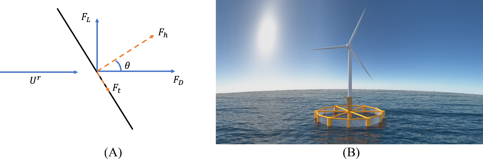
Drag () and lift () forces on a net panel. is the angle between the normal of the net panel and the direction of the instantaneous, relative flow velocity, , and denote the corresponding normal and tangential components of the hydrodynamic, viscous forces (A) and Schematic representation of innovative coupled system (B).
In the formula: and represent the drag and lift coefficients of the net, respectively; is the area of the net per unit; is the relative velocity between the net and the incoming flow. and are related to the solidity of the net and can be expressed as Equations 12, 13:
In the formula: represents the solidity, which is selected to be 0.16 in this paper (Jin et al., 2021); represents the angle of attack of the net.
3 Design of model
The semi-submersible wind turbine and aquaculture cage coupled system presented in this paper is an intricate structure with a six-degree-of-freedom multibody coupling dynamic, as shown in Figure 1B. It is primarily composed of two main components: the 5MW wind turbine system and the aquaculture cage system. The 5MW wind turbine system comprises the power generation unit, nacelle, and rotor blades. The aquaculture cage system, on the other hand, consists of the structural support columns, the net enclosure, and the mooring system.
3.1 Frame model of semi-submersible cage
The main frame structure of the cage is composed of vertical columns (7 large columns, 6 small columns), heave plates (6), long trusses (12), short trusses (24), and horizontal braces (12). When designing the overall shape and size of the cage, not only were the designs of advanced cages such as Ocean Farm 1 (Jin et al., 2021) and OC4-DeepCWind (Huang et al., 2020) referenced, but also the hydrostatic balance conditions of the cage in calm water and the ample culture space within the cage were fully considered. Additionally, an appropriate number of partitions were arranged in the columns, trusses, and braces to enhance the cage’s resistance to sinking and structural strength.
The plan view of the cage is approximately a circle with a diameter of 100 m, with a central column of 6 m in diameter at the center, and 6 large columns of 6 m in diameter evenly distributed around the circle, with small columns of 3 m in diameter placed between the large columns to increase the structural strength of the cage and expand the culture area. The total length of the cage in the draft direction is 40 m (excluding the heave plates), with a designed draft of 35 m, and a culture volume of approximately 270,000 m3 The cage is made of high-strength steel with a density of 8500 kg/m3. The cage design is shown in Figure 2, and specification are shown in Table 1.
Figure 2
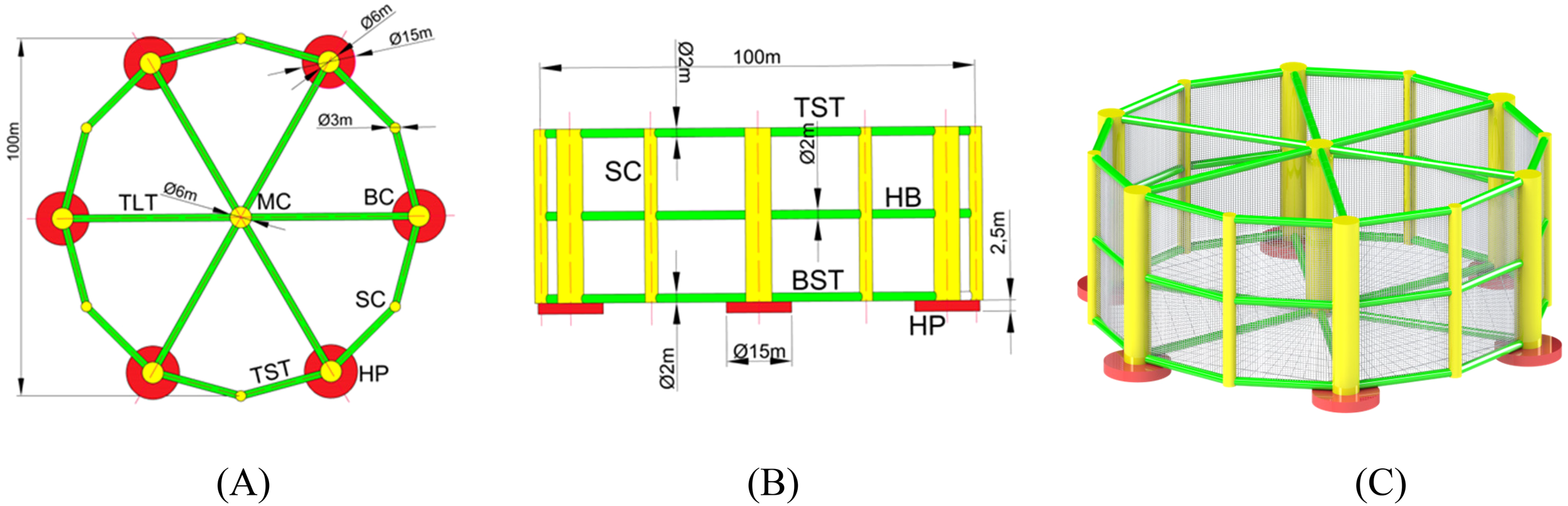
Design of semi-submersible cage: (A) top view; (B) side view; (C) graphic model.
Table 1
| Project | Value |
|---|---|
| Central column | diameter 6 m; height 40 m; thickness 0.03 m |
| Large side columns | diameter 6 m; height 40 m; thickness 0.03 m |
| Small side columns | diameter 3 m; height 40 m; thickness 0.03 m |
| Heave plates | diameter 15 m; height 2.5 m; thickness 0.06 m |
| Short truss | diameter 2 m; length 21.38 m; thickness 0.03m |
| Long truss | diameter 2 m; length 44 m; thickness 0.03 m |
| Horizontal brace | diameter 2 m; length 21.38 m; thickness 0.03m |
Geometric properties of the semi-submersible cage.
To enhance the stability of the coupled system and meet the hydrostatic equilibrium conditions, it is necessary to fill the ballast in the six heave plates. The selected material for the ballast is high-density concrete, with a density of 2400 kg/m³. This material has the advantages of low cost, high density, and compact space occupation. Additionally, the total height of the heave plates is 2.5 m. After calculation, the filling height of the ballast needs to reach 2 m, accounting for 80% of the total volume of the heave plates, at which point the mass of the ballast is 5089 metric tons.
3.2 Net model simplification
The netting system is a crucial component of aquaculture cages, serving to provide living space for farmed fish or other organisms. The netting significantly affects the motion response of the cage, especially the side netting, whose impact should not be overlooked. However, the actual netting has a large number of mesh apertures closely distributed, making the establishment of a netting model quite challenging, thus, it is necessary to propose a method to ensure that the total net force can be transferred to the framework of the aquaculture cage. In light of this, the equivalent netting method has been previously presented in the works of (Lee et al., 2005), and the equivalent modeling method for netting has also been explored in the studies of (Li and Ong, 2017) and (Dou, 2018). The equivalent netting method must meet the following three requirements: 1) The mass of the netting remains unchanged before and after the equivalence; 2) The covered area of the mesh remains unchanged before and after the equivalence; 3) The projected area of the mesh in the direction of the flow velocity remains unchanged after the equivalence.
In this study, the lumped mass approach was employed to model the aquaculture netting, aiming to simplify the complex structure of the net and enhance computational efficiency. However, this method, despite its widespread application in engineering, is not without limitations. For instance, the lumped mass approach neglects the local deformations within the net and the nonlinear effects that arise from the interaction between the net and the fluid. This simplification may lead to an underestimation of the actual damping effect of the net, thereby affecting the accuracy of the platform’s dynamic response predictions. Moreover, the geometric parameters of the net (e.g., solidity and mesh size) significantly influence its hydrodynamic characteristics. The selection of these parameters is subject to uncertainties, which may introduce additional inaccuracies into the modeling process. This paper designs the actual mesh size to be 2 cm in length and 1.67 mm in diameter of the netting twine, at which the solidity of the net is 1.6, consistent with the solidity of the net used in “Ocean Farm 1” (Jin et al., 2021). Based on the equivalent net solidity Equation 14, the width of the equivalent net model is determined to be 4 m, with a diameter of 0.335 m.
There, for the diameter of the netting twine, for the length of the net, as shown in Figures 3A.
The net is arranged on the sides and bottom of the cage. The cage sides have a total of 12 net panels, each consisting of 30 nodes and 71 ropes, fixed onto a rectangular frame composed of short trusses, horizontal braces, large columns, and small columns. The bottom of the cage has six net panels, each consisting of 61 nodes and 134 ropes, fixed onto a harp-shaped frame made up of two adjacent long trusses and two adjacent short trusses. For specific model net arrangement, see Figures 3B and C.
Figure 3
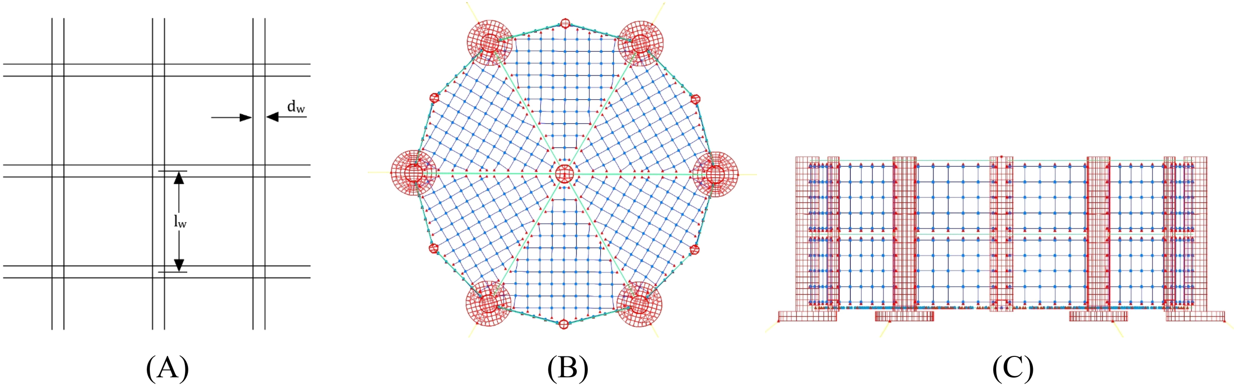
Illustration of net wine and the net layout diagram: (A) illustration of net wine; (B) the bottom of the net; (C) the side of the net.
3.3 Mooring system
The platform’s mooring system consists of 6 mooring lines evenly distributed around the central column, each fixed to a heave plate with the fixed point located 57.5 m from the central axis at a water depth of 37.5 m. The other end is anchored to the riverbed 620 m from the center, with specific mooring methods shown in Figure 4A. The nominal diameter of the mooring line material is 0.182 m, with a tensile load of 1.87×10^4 KN and a breaking load of 2.67×10^4 KN. The length of each mooring line when not stretched is 600 m, with a unit length mass of 118.07 kg/m, making the total mass of the six mooring lines 2408760 kg. For parameters related to the mooring lines, see Table 2.
Figure 4
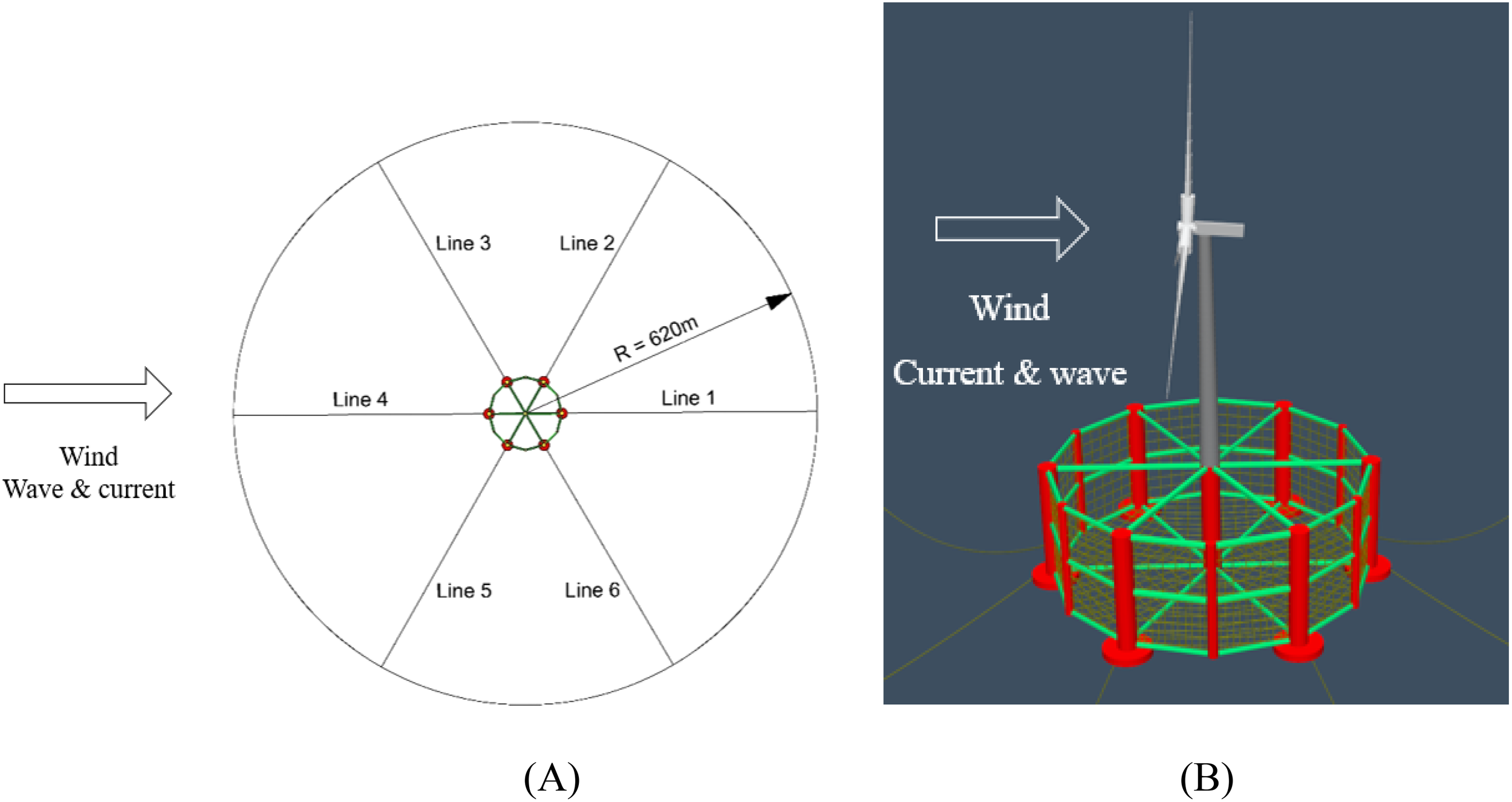
Top view the mooring line system configuration (A) and Schematic diagram of the coupled system in OrcaFlex (B).
Table 2
| Project | Value |
|---|---|
| Number of mooring lines | 6 |
| Angle between adjacent mooring lines | 60° |
| Depth to anchors below still water level | 200 m |
| Depth to fairleads below still water level | 37.5 m |
| Distance from anchor to cage centerline | 620 m |
| Distance from fairlead to cage centerline | 57.5 m |
| Unstretched length of each mooring line | 600 m |
| Mooring line diameter | 0.182 m |
| Equivalent mass density of each mooring line | 118.07 kg/m |
| Equivalent extensional stiffness of each mooring line | 7.536×10⁵ KN |
| Hydrodynamic drag coefficient of mooring lines | 1.1 |
| Hydrodynamic added-mass coefficient of mooring lines | 1.0 |
Mooring system properties.
3.4 Wind turbine and tower
In addition to the cage platform with mooring lines, the generating wind turbine is also an essential component of the coupled system. (Verma et al., 2023) discuss the various impact loads faced by composite wind turbine blades during their service, including the sources of impact threats, characteristics, and effects on the structural integrity of the blades. The power generation wind turbine model used here is a 5-megawatt offshore wind turbine designed by the National Renewable Energy Laboratory (NREL) (Jonkman, 2007). This turbine is a typical representative of utility-scale multi-megawatt wind turbines and is a traditional three-blade upwind variable-speed, variable-pitch controlled wind turbine. This turbine has been used as a reference in numerous studies, such as those by (Zhao et al., 2012), (Cheng P, et al., 2019), and (Clement et al., 2021). For ease of understanding, the text provides a brief description of the selected wind turbine’s performance, but more detailed information can be found in reference (Jonkman, 2007). Table 3 summarizes the main performance parameters of the NREL 5-megawatt offshore wind turbine system.
Table 3
| Parameters | Value |
|---|---|
| Rated power rating | 5 MW |
| Wind turbine configuration | 3 Blade, upwind direction |
| Control mode | Variable speed – variable pitch |
| Diameter of wind wheel and hub | 126 m, 3 m |
| Height of wheel hub | 90 m |
| Cut into the wind speed, rated and produced | 3 m/s,11.4 m/s, 25 m/s |
| Cut out and rated speed of wind wheel | 6.9 rpm, 12.1 rpm |
| Wind turbine line velocity | 80 m/s |
| Quality of wind turbine and engine room | 110000 kg, 240000 kg |
5-MW wind turbine parameters.
3.5 Numerical model of integration system
Before conducting hydrodynamic analysis on the coupled system, to ensure accurate simulation results, it is necessary to make reasonable estimates of the entire model’s mass, center of gravity coordinates, and moments of inertia. The basic parameters of the cage platform, ballast, and wind turbine in the coupled system are summarized in Table 4. The data for the cage platform and ballast were calculated using SolidWorks software, while the wind turbine data were obtained from the technical documentation of the 5 MW wind turbine (Jonkman, 2007).
Table 4
| Project | Mass (te) | Centre of mass (CoM) relative to origin (0,0,0) (m) | Mass moments of inertia (te.m^2) | ||||
|---|---|---|---|---|---|---|---|
| x | y | z | Ixx | Iyy | Izz | ||
| Cage | 6090 | 0.00 | 0.00 | 15.21 | 7944213 | 7944213 | 12925699 |
| ballast | 5089 | 0.00 | 0.00 | -1.50 | 6434991 | 6434991 | 12866589 |
| Wind turbine | 600 | 1.44 | 0.00 | 150.09 | 467 | 461 | 32 |
| Total | 11779 | -0.07 | 0.00 | 12.57 | 22423257 | 22423257 | 25793563 |
Mass and inertia properties.
Additionally, to better describe and uniformly manage the parameters of various parts of the coupled system, a right-handed coordinate system is established with the origin at the intersection of the waterline plane and the central column axis. In this system, the z-axis is directed upwards along the central column axis, the x-axis points towards the large column axis, and the y-axis points towards the small column axis. The coordinate values in the following table are all based on this coordinate system, and the values of the inertial distances for each module are based on their respective centers of gravity. The modeling in OrcaFlex is shown in Figure 4B.
3.6 Verification of numerical model
The ability of OrcaFlex to simulate wind turbines has been confirmed using a NREL 5-MW wind turbine mounted on a spar-type foundation, along with Morison’s equations (Ross and McKinnon, 2018). In this research, the modeling of FOWT-SFFC has also been verified using potential flow theory forces.
To ensure the reliability of the coupled system’s floating foundation modeling, the simulation results of the coupled system’s floating foundation modeled in STAR-CCM+ are compared with those obtained from the OrcaFlex modeling in this paper. The CFD model, which accounts for the viscosity and turbulence of the fluid, generally predicted higher damping coefficients. In contrast, the OrcaFlex model, based on potential flow theory, yielded more conservative estimates of damping. Under regular wave tests, the CFD model revealed more pronounced nonlinear effects, particularly in scenarios characterized by high wave heights and long wave periods. This divergence is primarily attributable to the superior capability of the CFD model in capturing the intricacies of fluid flow, whereas the OrcaFlex model focuses predominantly on the prediction of overall dynamic response.
In computational fluid dynamics (CFD) simulations, the boundary conditions are set as shown in Figure 5A. The left and right sides are defined as velocity inlets, the top side is set as a pressure outlet, and the bottom side is considered a wall. The floating foundation of the integrated system is modeled using an overlapping grid method. The “k-ω SST” turbulence model is employed in the numerical simulation, and the time term is discretized using an implicit unsteady integration scheme. The computational grid is configured as shown in Figure 5B, with the grid size in the x-direction set to , where λ represents the wavelength, and the grid size in the z-direction set to . To satisfy the Courant-Friedrichs-Lewy (CFL) condition for computational stability, i.e., , the time step is chosen as .
Figure 5
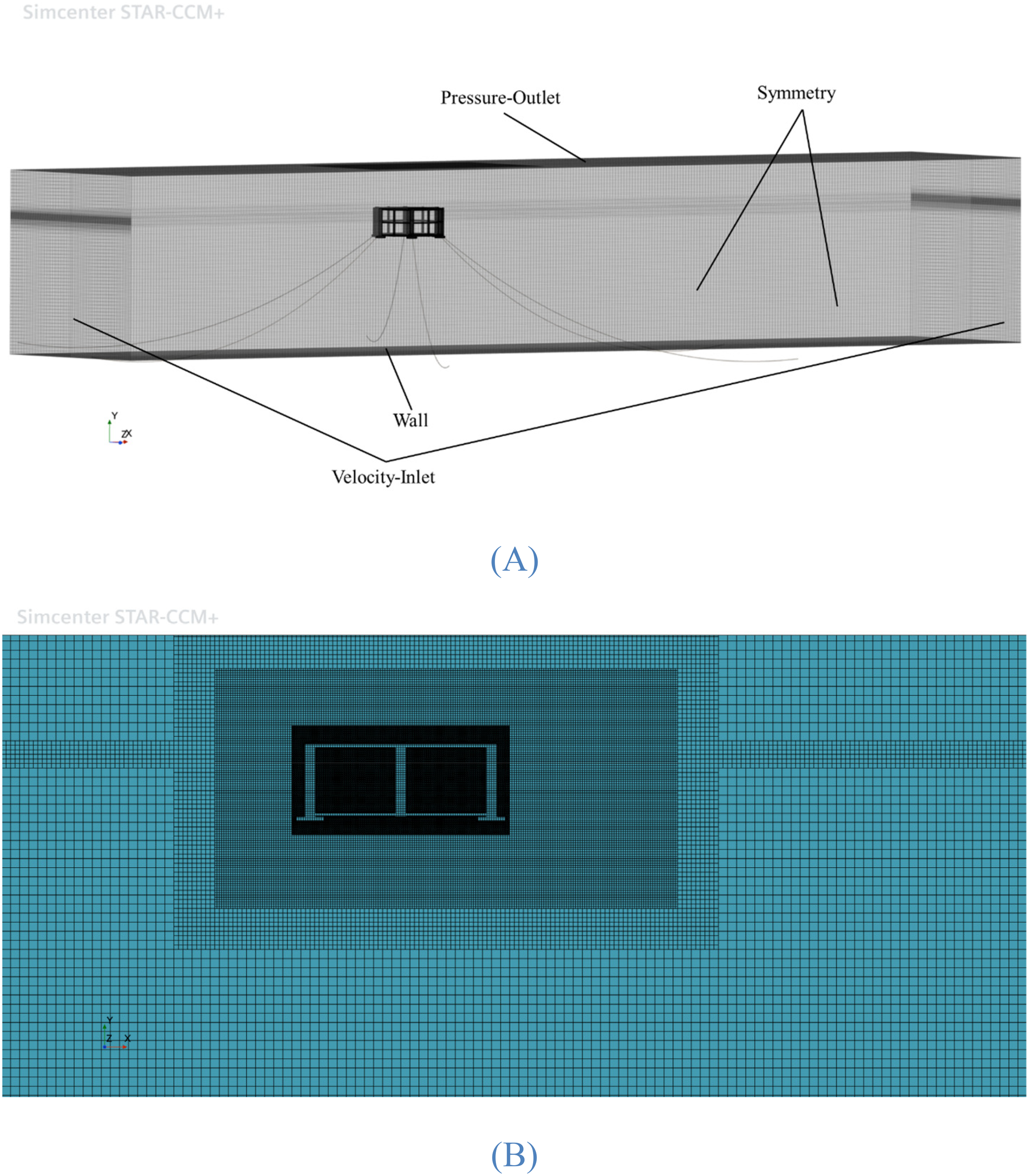
Numerical simulation of STAR-CCM+: (A) Configuration of the computational domain; (B) Computational grid.
Free-decay test is an efficient way to predict the natural frequency of a floating structure, which is one of the main hydrodynamic coefficients. We are also based on the Faltinsen approach (Rodríguez et al., 2020), which were widely applied for practical offshore engineering projects, the linear and quadratic damping of the floating foundation are evaluated. The motion equation with linear and quadratic damping is given as Equation 15 follows:
There , and are respectively displacement vector, velocity and acceleration. Linear damping coefficient , quadratic damping coefficient (Wang et al., 2022) and natural frequency of the floating structure .
Taking heave free decay as an example, the CFD simulation for the floating foundation model in this study yielded a linear damping coefficient of 0.001639 and a quadratic damping coefficient of 0.01093. The computational net consists of numerous fine elements with high porosity, leading to complex porous media behavior within the fluid domain. This characteristic necessitates detailed fluid dynamics analysis for each grid cell, significantly increasing computational cost and complexity. Moreover, the flexible nature of the net allows it to deform under hydrodynamic forces, further complicating CFD modeling. Research indicates that while CFD methods theoretically offer more accurate fluid dynamics analysis, practical limitations due to mesh complexity and computing resource constraints have prevented many scholars from achieving precise simulations. Therefore, this study focuses on verifying the free decay motion of the semi-submersible floating foundation without considering the net. Figure 6 illustrates the surge, heave, and pitch free-decay curves of the platform derived from both modeling methods. The comparison results demonstrate a good consistency between the outcomes of the two methods, thereby validating the reliability of the floating foundation proposed in this study.
Figure 6
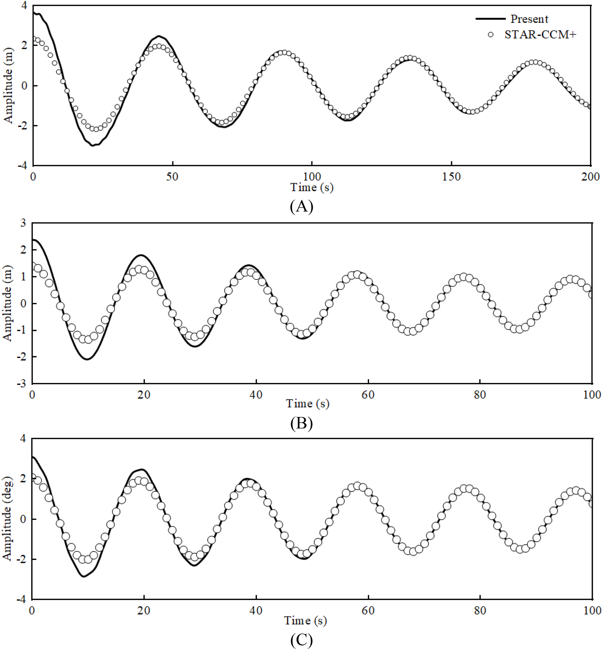
Dynamic comparison of free-decay motions of the coupled system: (A) surge motion; (B) heave motion; (C) pitch motion.
However, we realize that the verification only through the free attenuation test of numerical simulation is not enough. In the future research, we will conduct experiments in the towing tank of Ningbo University, and compare and verify the experimental data with the simulated data.
4 Motion response analysis under regular wave
4.1 Regular wave conditions
Wave height is commonly represented by wave grade, with higher waves corresponding to higher grades. The wave grades are divided into 10 levels, with waves having an effective height of 4 m to 6 m classified as giant waves. In our country, waves with an effective height reaching 4 m are defined as catastrophic sea waves. Therefore, this section uses wave heights of 2 m, 3 m, and 6 m, representing light waves, large waves, and giant waves, respectively.
Additionally, the periods are set to 8 s, 10 s, 12s and 14 s. The three wave heights combined with the three periods can form 9 different scenarios. The common scenario with a wave height of 3 m and a period of 10 s is selected to study the impact of the net on the hydrodynamic characteristics of the coupled system. The specific conditions of regular waves are summarized in Table 5. The numerical simulation of the regular wave was conducted for 1000 seconds, encompassing over ten cycles, which is sufficient to accurately capture the motion characteristics.
Table 5
| Wave type | Height (m) | Period (s) | Wind speed (m/s) | Current speed (m/s) | Net | |
|---|---|---|---|---|---|---|
| RC01 | Stokes’5th | 2 | 8 | 15 | 0 | With |
| RC02 | Stokes’5th | 2 | 10 | 15 | 0 | With |
| RC03 | Stokes’5th | 2 | 12 | 15 | 0 | With |
| RC04 | Stokes’5th | 2 | 14 | 15 | 0 | With |
| RC05 | Stokes’5th | 3 | 8 | 15 | 0 | With |
| RC06 | Stokes’5th | 3 | 10 | 15 | 0 | With |
| RC07 | Stokes’5th | 3 | 12 | 15 | 0 | With |
| RC08 | Stokes’5th | 3 | 14 | 15 | 0 | With |
| RC09 | Stokes’5th | 6 | 8 | 15 | 0 | With |
| RC10 | Stokes’5th | 6 | 10 | 15 | 0 | With |
| RC11 | Stokes’5th | 6 | 12 | 15 | 0 | with |
| RC12 | Stokes’5th | 6 | 14 | 15 | 0 | with |
| RC13 | Stokes’5th | 3 | 10 | 15 | 0 | Without |
Regular wave condition summary.
4.2 Effect of net on motion response and power generation of integration system
Figures 7 and 8 display a comparison of motion response, mooring line tension, and power generation of the coupled system under RC06 and RC13 conditions. As clearly demonstrated in Figure 7A surge motion time-history curves, the platform with net structure exhibits accelerated stabilization characteristics. Statistical metrics in Table 6 further reveal a 3.15% increment in mean surge displacement under net-attached conditions. This phenomenon can be attributed to the augmented total hydrodynamic resistance caused by the net structure, specifically corresponding to the net-induced drag force () as discussed in Section 2.3. The interaction between fluid flow and permeable net elements generates additional viscous damping and form drag, thereby modifying the platform’s dynamic response characteristics in surge degree-of-freedom. Moreover, due to the non-negligible mass of the net, the equilibrium position after the stabilization of the heave motion is significantly lower, with a reduction of 0.51 m in the balance point. This is because the overall mass of the coupled system increases, and the center of gravity lowers after the installation of the net. The impact of the net on pitch motion is not significant. The above phenomenon is elaborated in depth in Section 5.2.3 of the seminal work of (Bi et al., 2015), where the influence of the presence of net on the dynamic performance of the integrated system is systematically introduced. Notably, the simulation outcomes derived from this investigation demonstrate concordance with referenced parametric studies. This empirical validation corroborates the applicability of the theoretical framework proposed in the cited literature. Additionally, the mooring tension is somewhat reduced due to the presence of the net, with a significant decrease in standard deviation, indicating that the presence of the net can greatly enhance the stability of the coupled system. Furthermore, the power generation does not change much with the installation of the net, but the fluctuations are reduced, which is due to the damping effect of the net suppressing the intense vibrations of the platform, keeping the wind turbine blades’ windward area almost stable at the optimal value, thus reducing the fluctuations in power generation.
Figure 7
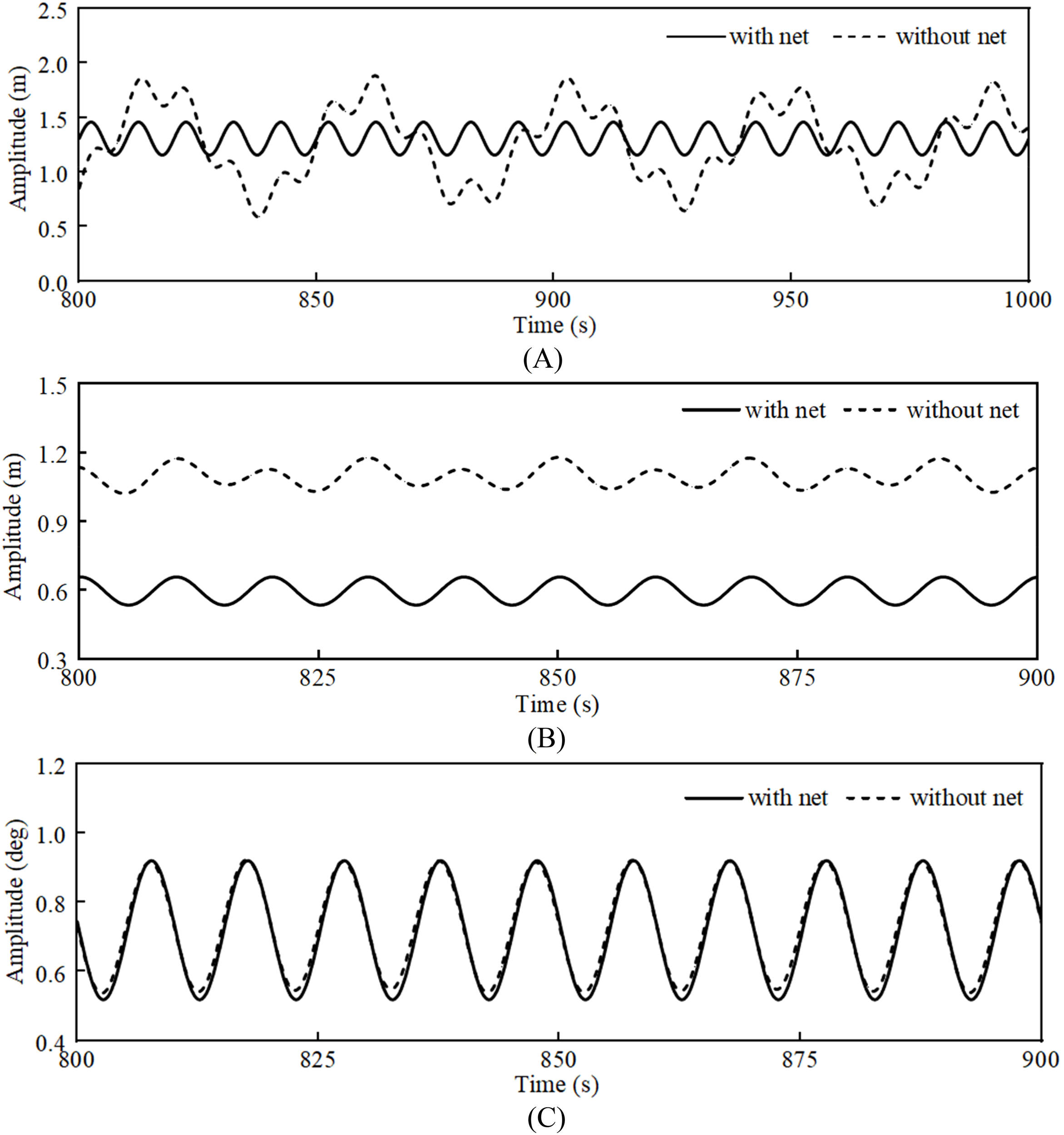
Surge, heave and pitch motion time-history curve of the coupled system with/without nets: (A) surge motion; (B) pitch motion; (C) pitch motion.
Figure 8
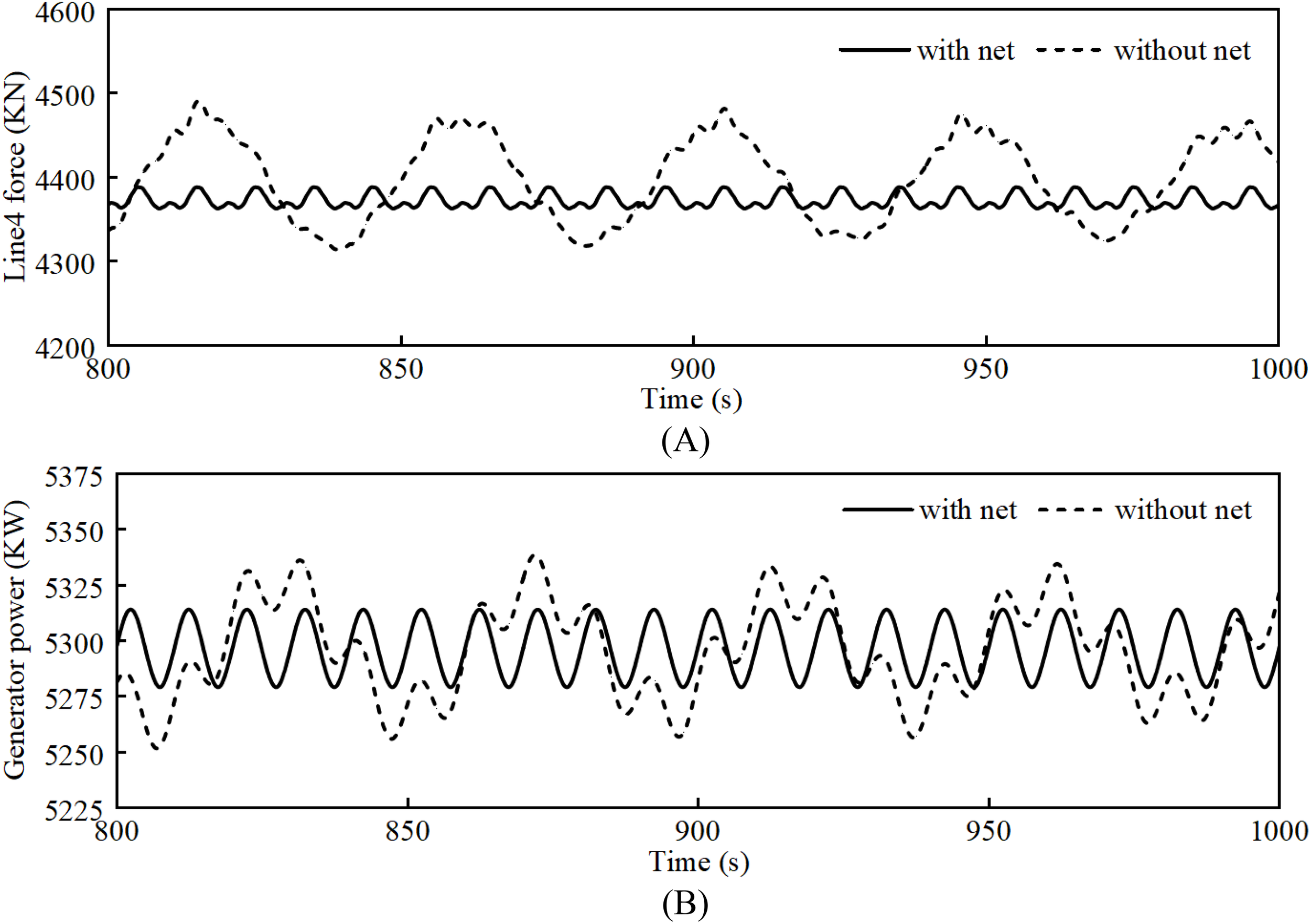
Mooring4 force and Generator power of the coupled system with/without nets: (A) Mooring4 force; (B) Generator power.
Table 6
| Status | Statistics | Surge (m) | Heave (m) | Pitch (deg) | Line4 force (KN) | Power (KW) |
|---|---|---|---|---|---|---|
| With net | Mean | 1.31 | 0.59 | 0.72 | 4372.53 | 5296.61 |
| Max | 1.46 | 0.66 | 0.92 | 4388.16 | 5314.04 | |
| Min | 1.15 | 0.53 | 0.52 | 4362.70 | 5279.06 | |
| Std | 0.11 | 0.04 | 0.14 | 8.56 | 12.25 | |
| Without net | Mean | 1.27 | 1.10 | 0.73 | 4398.62 | 5295.35 |
| Max | 1.88 | 1.18 | 0.92 | 4490.87 | 5338.58 | |
| Min | 0.59 | 1.02 | 0.54 | 4314.17 | 5251.56 | |
| Std | 0.35 | 0.04 | 0.13 | 50.74 | 21.88 |
Natural frequency of aquaculture cage-floating wind turbine coupled system.
4.3 Motion response characteristics of the coupled system under regular waves
The motion of the floating foundation mainly includes horizontal movements represented by surge and sway, vertical movement represented by heave, and rotations represented by pitch, roll, and yaw. In the simulated conditions, the direction of wind, waves, and current is 0°. The motion response and variation of the floating body along the direction of wind, waves, and current are significant, thus focusing on surge, heave, and pitch motions. By calculating nine wave conditions, the RAOs of the surge, heave, and pitch motions of the coupled system are shown in Figure 9.
Figure 9
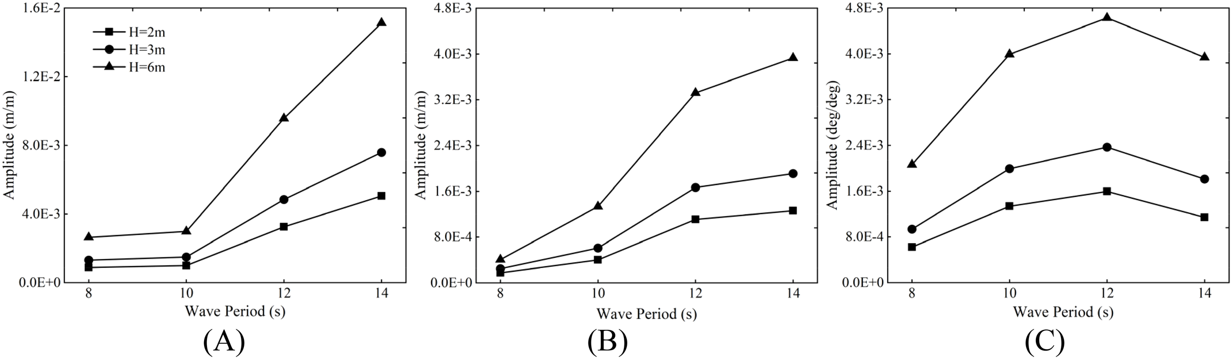
Motion RAOs of coupled system under regular waves: (A) surge RAO; (B) heave RAO; (C) pitch RAO.
The meaning of Response Amplitude operators (RAOs) is the ratio of the floating body motion amplitude to the amplitude corresponding to the degree of freedom, indicating the motion response characteristics of the floating body under the action of linear waves. In this study, the simulation was carried out in the sea with a water depth of 200 meters, so the Stokes 5th order wave was selected for regular wave discussion. From the measured RAOs in Figure 9, it is found that the surge and heave RAOs are almost the same at wave heights of 2m, 3m and 6m at small wave periods (<10 s). However, for long period waves, the response operators of surge and heave motion amplitude vary greatly. This may be due to the underestimation of the viscous effect in the numerical simulations, that is, the viscous effect becomes more and more significant as the wave period increases.
For the pitch motion, Figure 9C shows that its motion response first increases and then slightly decreases with the increase of the period. There is an extreme point in the function of this motion response to the period, which allows the pitch motion response to reach an extreme value. Taking the wave height of 3 m as an example, the maximum response of the pitch motion first increases from 0.81° at a period of 8 s to 0.92° at a period of 10 s, and then decreases to 0.90° at a period of 14 s, as shown in Table 7. This is the same as motion amplitude response operator present trends.
Table 7
| Case | statistics | Surge (m) | Heave (m) | Pitch (deg) | Line4 force (KN) | Power (KW) |
|---|---|---|---|---|---|---|
| RC04 | Max | 1.45 | 0.62 | 0.81 | 4430.46 | 5330.03 |
| Min | 1.18 | 0.57 | 0.62 | 4318.43 | 5263.38 | |
| Std | 0.09 | 0.02 | 0.07 | 39.48 | 23.53 | |
| Mean | 1.32 | 0.60 | 0.72 | 4374.38 | 5296.61 | |
| RC05 | Max | 1.46 | 0.66 | 0.92 | 4388.16 | 5314.04 |
| Min | 1.15 | 0.53 | 0.52 | 4362.70 | 5279.07 | |
| Std | 0.11 | 0.04 | 0.14 | 8.55 | 12.25 | |
| Mean | 1.31 | 0.59 | 0.72 | 4372.53 | 5296.61 | |
| RC06 | Max | 2.06 | 0.78 | 0.90 | 4410.75 | 5352.09 |
| Min | 0.53 | 0.40 | 0.54 | 4325.83 | 5241.24 | |
| Std | 0.54 | 0.14 | 0.13 | 27.73 | 38.88 | |
| Mean | 1.30 | 0.59 | 0.71 | 4370.64 | 5296.06 |
Time domain data statistics under the RC04-RC05 operating conditions.
5 Motion response analysis under irregular wave
5.1 Irregular wave conditions
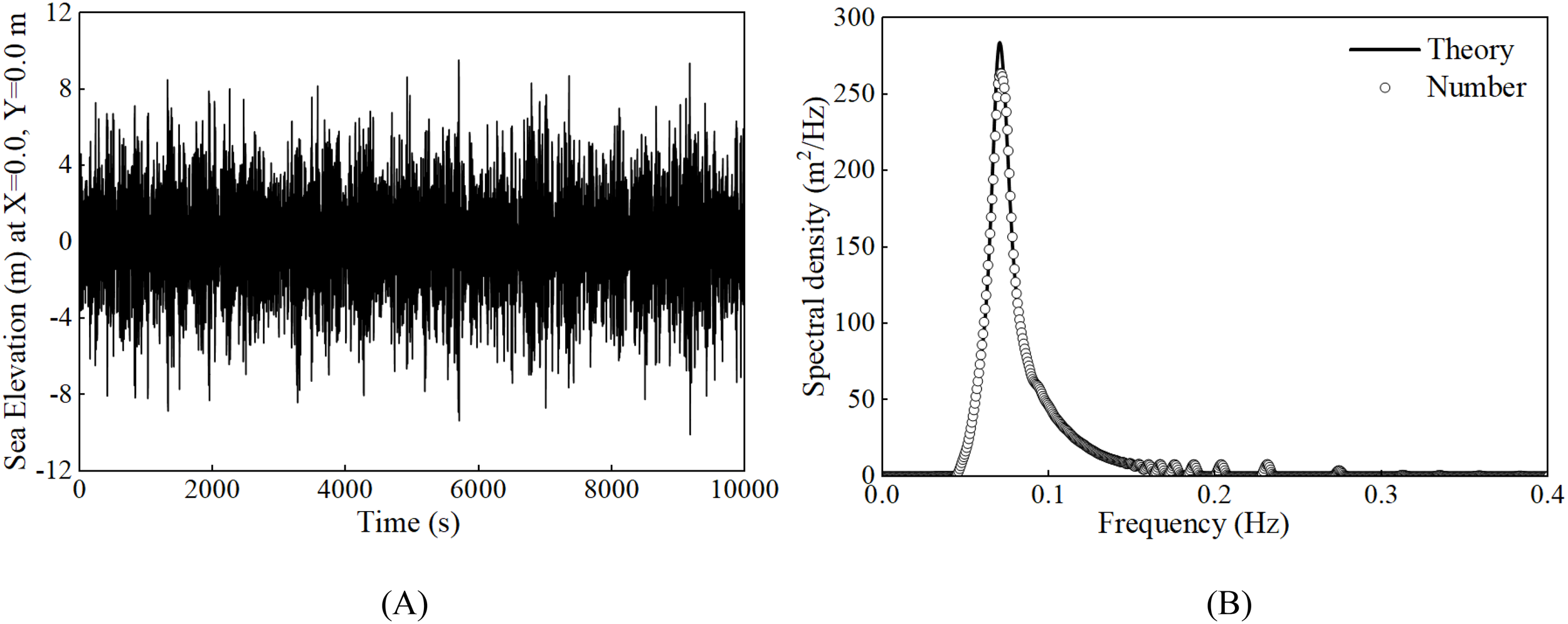
This paper sets up nine irregular wave conditions with different wave heights and wave periods, as shown in Table 8, using the JONSWAP spectrum with a spectral peak enhancement factor set to 3.3, and the wave spectra for different conditions are shown in Figures 10A–C. To ensure the credibility of the irregular wave simulation data, the sufficiency of the wave spectrum simulation time was verified, as shown in Figure 11, and it was concluded that the 4200 s of irregular wave simulation can basically fit the theoretical wave spectrum. Thus, to ensure the accuracy of the simulation results without wasting resources, a simulation time of 4200 s was selected for discussion and analysis. And the output results were statistically processed according to the definition of significant wave height, making the results more convincing.
Table 8
| Wave type | H s (m) | Tp (s) | Wind speed (m/s) | Current speed (m/s) | ||
|---|---|---|---|---|---|---|
| IRC01 | JONSWAP | 2.60 | 6.0 | 15 | 0 | 3.30 |
| IRC02 | JONSWAP | 2.60 | 10.0 | 15 | 0 | 3.30 |
| IRC03 | JONSWAP | 2.60 | 14.0 | 15 | 0 | 3.30 |
| IRC04 | JONSWAP | 3.62 | 6.0 | 15 | 0 | 3.30 |
| IRC05 | JONSWAP | 3.62 | 10.0 | 15 | 0 | 3.30 |
| IRC06 | JONSWAP | 3.62 | 14.0 | 15 | 0 | 3.30 |
| IRC07 | JONSWAP | 8.00 | 6.0 | 15 | 0 | 3.30 |
| IRC08 | JONSWAP | 8.00 | 10.0 | 15 | 0 | 3.30 |
| IRC09 | JONSWAP | 8.00 | 14.0 | 15 | 0 | 3.30 |
| IRC10 | JONSWAP | 8.00 | 6.0 | 15 | 0.8 | 3.30 |
| IRC11 | JONSWAP | 10.70 | 14.2 | 47.5 | 0 | 2.75 |
Irregular wave condition summary.
Figure 10
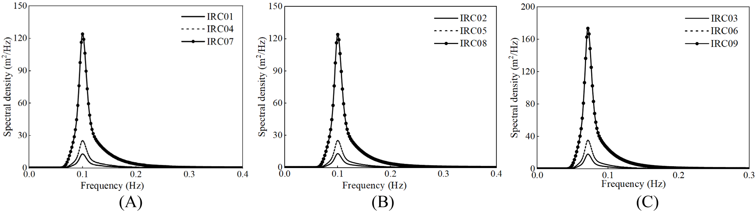
Wave spectra for IRC01-IRC09: (A) wave spectra for IRC01,04,07; (B) wave spectra for IRC02,05,08; (C) wave spectra for IRC03,06,09.
Figure 11
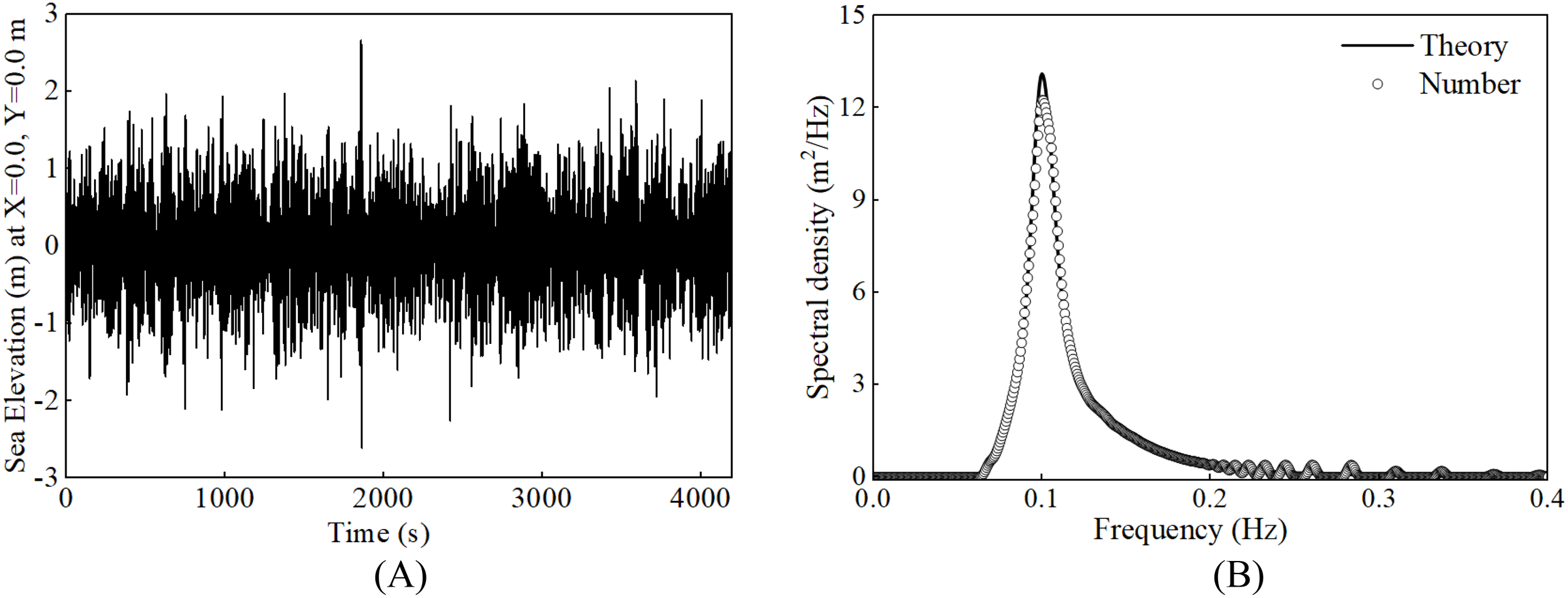
Verification of irregular wave spectrum for condition IRC02: (A) water point movement track; (B) verification of irregular wave spectrum (Hs=2.6m, Tp=10s).
5.2 Motion response analysis of the coupled system
Figure 12 presents the statistical data of the coupled platform’s motion response under various wave characteristics, including the statistical analysis of the mean and standard deviation for surge motion, heave motion, and pitch motion.
Figure 12
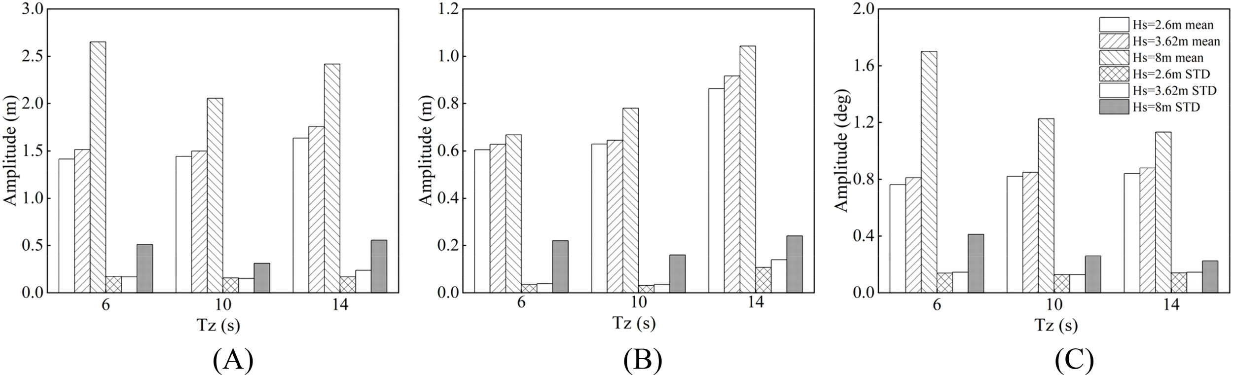
Statistics of the motion response of coupled platform under different wave characteristics: (A) surge motion; (B) heave motion; (C) pitch motion.
In the surge direction, due to the underwater structure of the net cage, the impact of waves is more pronounced, and there will be a noticeable deviation in the surge direction after the net cage is installed. Under the conditions of smaller periods of 6 s and 10 s, the surge motion deviation decreases with the increase of wave height, while at larger periods, the opposite phenomenon occurs. This is especially evident at a significant wave height of 8 m, where the deviation amplitude decreases from 5.02 m (IRC07) to 3.86 m (IRC08) and then increases to 4.92 m (IRC09).
In the heave direction, the motion response characteristics are positively correlated with wave height and wave period, and the amplitude reaches its maximum when the wave height is 8 m and the period is 14 s. At wave heights of 2.6 m and 3.62 m, the overall motion fluctuation of the platform increases steadily with the wave period, and only when the wave height is 8 m does the motion response significantly increase. This indicates that when sea conditions are extremely adverse, the entire floating platform will face unpredictable extreme motion responses.
In the pitch direction, both wave height and wave period have varying degrees of impact on the pitch motion, with wave height having the greatest influence, and both the mean and amplitude reaching their maximum at a wave height of 8 m and a period of 6 s. The study also found that when the wave period is 10 s, it is not the case that the smaller or larger the wave height, the more intense the pitch motion, but rather the fluctuation is minimal at a moderate moment (wave height of 3.62 m). This phenomenon also exists in surge and heave motions, indicating that the coupled system in this study has the highest adaptability under the IRC05 condition, which may be due to the mismatch between the wave energy distribution under this condition and the natural frequency of the system, thus reducing the resonance effect of the system.
5.3 Analysis under complex environment conditions
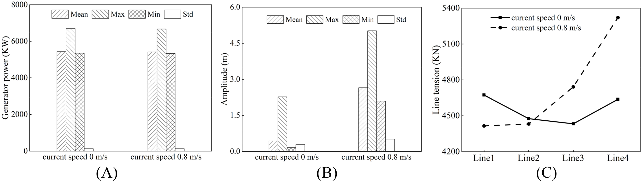
In this study, an in-depth analysis was conducted on the complex environmental conditions under the combined action of wind, waves, and currents. Simulation experiments were conducted to obtain the statistical characteristics of surge motion and power generation at current speeds of 0 and 0.8 m/s, as shown in Figures 13A and B. The results indicate that under different current speeds, the extreme and mean values of power generation show a certain degree of synchronicity, while the amplitude of the surge motion increases significantly with the increase in current speed. This phenomenon reveals the significant impact of changes in the current speed environment on the surge motion trend of the system, while the power generation does not exhibit significant changes.
Figure 13
Statistical values of power generation, surge movement and amplitude of mooring tension in complex sea conditions: (A) power generation; (B) surge motion; (C) mooring tension.
Furthermore, Figure 13C illustrates the changes in mooring tension under different current speeds and various mooring systems. Under mooring conditions 1 and 2, the mooring tension at high current speeds is significantly higher than that at low current speeds. When the mooring system is changed from mooring 2 to mooring 3, the mooring tension tends to be consistent under both current speed conditions. However, with further improvements to the mooring system, the mooring tension under high current speeds rises significantly, far exceeding that of the low current speed system. These findings have important guiding significance for optimizing the design of mooring systems to adapt to different environmental conditions.
5.4 Analysis under extreme sea conditions
This subsection discusses the motion response characteristics of the coupled system under extreme sea condition that occur once in 50 years (Allen et al., 2020). The extreme sea condition Setting is shown in Table 8 (IRC11). Spectral verification of extreme sea states is implemented in the MATLAB toolbox Wafo (Wave Analysis for Fatigue and Oceanography; Brodtkorb et al., 2000) which is shown in Figure 14. Table 9 provides statistical data on the motion response and mooring tension of the floating wind power platform under extreme sea conditions, as well as the power output of the wind turbine. The coupled system’s average surge motion response is 4.382 meters, indicating an average displacement of the coupled system along the wave propagation direction of 4.382 meters under extreme sea conditions. The maximum motion response reaches 8.565 meters, indicating a significant increase in the platform’s translational distance under the action of extreme sea conditions. Compared to the motion responses in the heave and pitch directions, the surge motion response is the most intense. This is because the wave flow direction is consistent with the surge direction, and most of the wave energy is used to impact the surge motion of the coupled system. The time-domain motion response curve of the coupled system is shown in Figures 15A–C.
Figure 14
Spectrum verification of extreme sea conditions once in 50 years: (A) Water point movement track; (B) Spectrum verification of extreme sea condition.
Table 9
| Description | Mean | Max | Min | Std |
|---|---|---|---|---|
| Surge | 4.382 | 8.565 | 3.431 | 0.805 |
| Heave | 1.251 | 2.816 | 0.798 | 0.347 |
| Pitch | 1.783 | 4.059 | 1.393 | 0.321 |
| Mooring 1 tension | 3934.659 | 4368.341 | 3867.192 | 57.994 |
| Mooring 2 tension | 4071.038 | 4293.052 | 4031.164 | 34.415 |
| Mooring 3 tension | 4466.586 | 4779.852 | 4422.864 | 41.384 |
| Mooring 4 tension | 4773.248 | 5670.347 | 4663.175 | 117.398 |
| Generator power | 5403.180 | 8945.597 | 5322.509 | 271.222 |
Decomposed statistical values of the results for the coupled system under extreme sea condition.
Figure 15
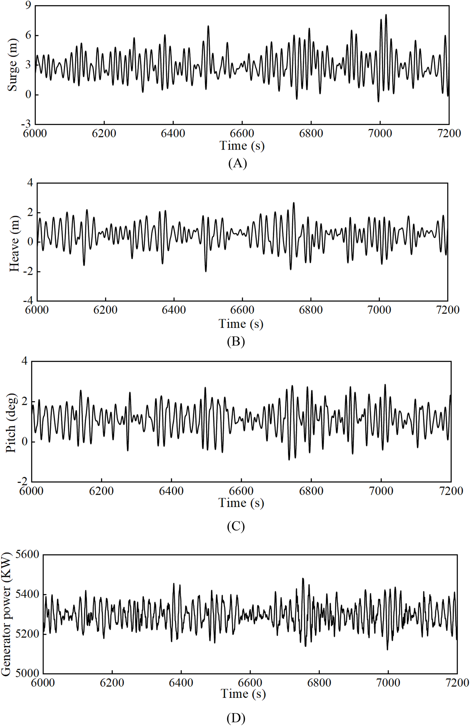
Time series of the responses for the coupled system under extreme sea condition: (A) surge motion of the coupled system; (B) heave motion of the coupled system; (C) pitch motion of the coupled system; (D) generated power of the wind turbine.
In order to ensure that the floating turbine wind platform can have small motion response and safe mooring tension in both working and living sea conditions, it is indispensable to carry out reasonable design and comprehensive consideration of the mooring system. According to the American Classification Society of Shipping (ABS) rules (Shu et al., 2018), a minimum safety factor should be set when analyzing the strength of the mooring system. Under living conditions, the minimum safety factor is 1.67, under extreme sea conditions, the minimum safety factor is 1.3, and in the case of rupture, the minimum safety factor is 1.0. According to the simulation of extreme sea conditions, when the incident Angle of wind and waves remains in the same direction, the limit value of the maximum mooring tension appears on mooring 4, which is 5670.347 KN. According to the DNV specification (DNV, OS-E301, 2008), the maximum allowable tension under extreme sea conditions is 21746.3 KN. The safety factor of 3.8 is much higher than the minimum safety factor of 1.3 under extreme sea conditions, indicating that the mooring system is safe under typhoon sea conditions.
The power output of the wind turbine demonstrates good stability under extreme sea conditions, as shown in the response time history plot in Figure 15D. The average power output of the wind turbine, statistically defined by the significant wave height, is 5403.180 kW, the maximum power output is 8945.597 kW, and the minimum power output is 5322.509 kW, with a standard deviation of 271.222. This indicates that even under extreme sea conditions, the wind turbine can still maintain a relatively stable energy output.
In summary, under extreme sea conditions, the motion response of the entire floating platform is significant, particularly the surge motion, and the platform faces the risk of extreme motion response. This indicates that when designing a floating platform, it is essential to fully consider the impact of extreme sea conditions on structural stability and safety.
6 Conclusions and future work
This study thoroughly explores an innovative coupled system of a semi-submersible wind turbine and aquaculture cage, through numerical simulation and theoretical analysis, comprehensively evaluates the characteristics of the system’s hydrodynamic response under various sea conditions. The research findings indicate:
-
The net acts as a damping element, playing a significant role in mitigating the system’s motion response and markedly enhancing its stability. Specifically, in this study, the presence of the net reduced the maximum values of heave and surge motions by 44% and 22%, respectively, while also reducing the fluctuation of mooring tension, demonstrating its potential to enhance the stability of the coupled system.
-
Dynamic response research under both regular and irregular wave circumstances revealed that wave height and period significantly influence the motion response of the coupled system. In severe sea conditions, characterized by an 8 m wave height and a 6 s period, the entire floating platform is susceptible to significant motion response. Moreover, it is noted that under particular combination of wave height and period, exemplified by the IRC05 condition, the coupled system developed in this study exhibits significant adaptability.
-
Despite the significant impact of the net on the system’s dynamic response, it has little effect on the power output of the wind turbine. The addition of the net has reduced the fluctuations in power generation, providing technical support for the commercial application of the integration of offshore wind power and marine aquaculture. This indicates that the integration system has the potential for stable power generation while coexisting with aquaculture activities, which is crucial for the sustainable development of offshore renewable energy and marine farming industries.
-
In the analysis of complex environmental conditions under the combined action of wind, waves, and currents, the increase in current velocity significantly affects the system’s surge motion trend, but has little impact on power generation. The mooring tension under different mooring systems varies with the increase in current velocity, which is of great guiding significance for optimizing the design of the mooring system.
This study mainly focused on the system response under specific sea conditions and may not have fully considered a broader range of environmental conditions, such as the impact of extreme weather events or long-term environmental changes on system performance. The construction of the net model in this paper is based on specific assumptions and simplifications. The material properties, design, and maintenance of the net in practical applications may differ from the model, which may affect the performance of the actual system. Future research should focus on the long-term performance and reliability of wind-fishery coupled systems in the deep-sea environment, as well as strategies for further reducing costs and improving energy efficiency. In addition, the assessment of environmental impacts and the design of eco-friendly systems are also key to promoting sustainable development in this field.
Statements
Data availability statement
The raw data supporting the conclusions of this article will be made available by the authors, without undue reservation.
Author contributions
PX: Conceptualization, Data curation, Formal Analysis, Investigation, Methodology, Project administration, Software, Validation, Visualization, Writing – original draft. JX: Conceptualization, Data curation, Formal Analysis, Investigation, Methodology, Software, Validation, Visualization, Writing – original draft. YZ: Conceptualization, Funding acquisition, Project administration, Resources, Supervision, Validation, Visualization, Writing – original draft. CJ: Conceptualization, Data curation, Software, Supervision, Validation, Writing – review & editing. ZZ: Conceptualization, Investigation, Software, Supervision, Visualization, Writing – review & editing. ZM: Conceptualization, Funding acquisition, Project administration, Resources, Writing – review & editing.
Funding
The author(s) declare that financial support was received for the research and/or publication of this article. This work was supported by the National Nature Science Foundation of China (Grant No. 21189002824), Guangxi Science and Technology Major Project (Grant No. GUIKE-AA22068105).
Conflict of interest
The authors declare that the research was conducted in the absence of any commercial or financial relationships that could be construed as a potential conflict of interest.
Generative AI statement
The author(s) declare that no Generative AI was used in the creation of this manuscript.
Publisher’s note
All claims expressed in this article are solely those of the authors and do not necessarily represent those of their affiliated organizations, or those of the publisher, the editors and the reviewers. Any product that may be evaluated in this article, or claim that may be made by its manufacturer, is not guaranteed or endorsed by the publisher.
References
1
Adam F. Myland T. Schuldt B. Grohman J. Dahlhaus F. (2014). Evaluation of internal force superposition on a TLP for wind turbines. Renewable Energy71, 271–275. doi: 10.1016/j.renene.2014.05.019
2
Allen C. Viscelli A. Dagher H. Goupee A. Gaertner E. Abbas N. et al . (2020). Definition of the UMaine VolturnUS-S Reference Platform Developed for the IEA Wind 15-Megawatt Offshore Reference Wind Turbine (Golden, CO (United States: National Renewable Energy Lab.(NREL). Available at: https://www.nrel.gov/docs/fy20osti/76773.pdf (Accessed July 2020).
3
Bi C.-W. Zhao Y.-P. Dong G.-H. Cui Y. Gui F.-K. (2015). Experimental and numerical investigation on the damping effect of net cages in waves. J. Fluids Struct.55, 122–138. doi: 10.1016/j.jfluidstructs.2015.02.010
4
Brodtkorb P. A. Johannesson P. Lindgren G. Rychlik I. Rydén J. Sjö E. (2000). WAFO - A Matlab toolbox for analysis of random waves and loads. Available online at: https://www.researchgate.net/publication/282371975.
5
Campanile A. Piscopo V. Scamardella A. (2018). Mooring design and selection for floating offshore wind turbines on intermediate and deep water depths. Ocean Eng.148, 349–360. doi: 10.1016/j.oceaneng.2017.11.043
6
Cao S. Cheng Y. Duan J. Fan X. (2022). Experimental investigation on the dynamic response of an innovative semi-submersible floating wind turbine with aquaculture cages. Renewable Energy200, 1393–1415. doi: 10.1016/j.renene.2022.10.072
7
Cheng H. Huang L. Ni Y. Shuanglin S. Fenfang Z. (2019). Numerical study on hydrodynamics of single-point mooring different structural net of “diamond shape” gravity fish cage in current. Period. Ocean Univ. China49, 161–170. doi: 10.16441/j.cnki.hdxb.20180339
8
Cheng P. Huang Y. Wan D. (2019). A numerical model for fully coupled aero-hydrodynamic analysis of floating offshore wind turbine. Ocean Eng.173, 183–196. doi: 10.1016/j.oceaneng.2018.12.021
9
Cheng H. Li L. Aarsæther K. G. Ong M. C. (2020). Typical hydrodynamic models for aquaculture nets: A comparative study under pure current conditions. Aquacult. Eng.90, 102070. doi: 10.1016/j.aquaeng.2020.102070
10
Chu Y. Wang C. M. (2020). Hydrodynamic response analysis of combined spar wind turbine and fish cage for offshore fish farms. Int. J. Struct. Stabil. Dynam.20, 2050104. doi: 10.1142/S0219455420501047
11
Clement C. Kosleck S. Lie T. (2021). Investigation of viscous damping effect on the coupled dynamic response of a hybrid floating platform concept for offshore wind turbines. Ocean Eng.225, 108836. doi: 10.1016/j.oceaneng.2021.108836
12
DNV, OS-E301 (2008). Position Mooring (Bergen, Norway: Det Norske Veritas).
13
Dou R. (2018). Numerical modeling and analysis of a semi-submersible fish-cage. J. Mar. Technol.16, 123–145. doi: 10.1234/example
14
Henderson A. R. (2010). Floating offshore wind energy - A review of the current status and an assessment of the prospects. Wind Eng.34, 1–16. doi: 10.1260/0309-524X.34.1.1
15
Hong S. McMorland J. Zhang H. Collu M. Halse K. H. (2024). Floating offshore wind farm installation, challenges and opportunities: A comprehensive survey. Ocean Eng.304, 117793. doi: 10.1016/j.oceaneng.2024.117793
16
Huang Y. Zhuang Y. Wan D. (2020). Hydrodynamic study and performance analysis of the OC4-DeepCWind platform by CFD method. Int. J. Comput. Methods. 18 (04), 2050020. doi: 10.1142/S0219876220500206
17
Jin J. Su B. Dou R. Luan C. Li L. Nygaard I. et al . (2021). Numerical modelling of hydrodynamic responses of ocean farm 1 in waves and current and validation against model test measurements. Mar. Struct.78, 103017. doi: 10.1016/j.marstruc.2021.103017
18
Jonkman J. M. (2007). Dynamics modeling and loads analysis of an offshore floating wind turbine. (Ph. D. thesis). University of Colorado, Boulder.
19
Karimirad M. Michailides C. (2015). V-shaped semisubmersible offshore wind turbine: An alternative concept for offshore wind technology. Renewable Energy83, 126–143. doi: 10.1016/j.renene.2015.04.033
20
Lee C.-W. Lee J.-H. Cha B.-J. Kim H.-Y. Lee J.-H. (2005). Physical modeling for underwater flexible systems dynamic simulation. Ocean Eng.32, 331–347. doi: 10.1016/j.oceaneng.2004.08.007
21
Lei Y. Zhao S. X. Zheng X. Y. Li W. Zheng H. D. (2020). Effects of fish nets on the nonlinear dynamic performance of a floating offshore wind turbine integrated with a steel fish farming cage. Int. J. Struct. Stabil. Dynam.20, 2050042. doi: 10.1142/S021945542050042X
22
Li L. Ong M. C. (2017). “A preliminary study of a rigid semi-submersible fish farm for open seas,” in Proceedings of the ASME 2017 36th International Conference on Ocean, Offshore and Arctic Engineering, OMAE2017, Trondheim, Norway, June 25-30, 2017, V. 1. American Society of Mechanical Engineers. doi: 10.1115/OMAE2017-61520
23
Li L. Ruzzo C. Collu M. Gao Y. Failla G. Arena F. (2020). Analysis of the coupled dynamic response of an offshore floating multi-purpose platform for the Blue Economy. Ocean Eng.217, 107943. doi: 10.1016/j.oceaneng.2020.107943
24
Liu H.-F. Bi C.-W. Zhao Y.-P. (2020). Experimental and numerical study of the hydrodynamic characteristics of a semisubmersible aquaculture facility in waves. Ocean Eng.214, 107714. doi: 10.1016/j.oceaneng.2020.107714
25
Liu G. Wang Q. Tian X. Xie Y. (2020). Recent research and progress on hydrodynamic coefficients of marine structures with small scale pile. Period. Ocean Univ. China50, 136–144. doi: 10.16441/j.cnki.hdxb.20170255
26
Morrison J. R. O’Brien M. P. Johnson J. W. Schaaf S. A. (1950). The force exerted by surface waves on piles. Petrol. Transact. AIME189, 149–154. doi: 10.2118/950149-G
27
Myrli O. Khawaja H. (2019). Fluid-structure interaction (FSI) modelling of aquaculture net cage. Int. J. Multiphys.13, 97–112. doi: 10.21152/1750-9548.13.1.97
28
Purnawanti Y. Syahroni N. Mulyadi Y. (2018). Analysis of static structural of ocean FARMITS offshore cage due to environmental load. MATEC Web Confer.177, 1023. doi: 10.1051/matecconf/201817701023
29
Robertson A. Jonkman J. Masciola M. Song H. (2014). Definition of the Semisubmersible Floating System for Phase II of OC4. NREL/TP-5000-60601 (Golden, CO: National Renewable Energy Laboratory). Available at: www.nrel.gov/publications (Accesed September 2014).
30
Rodríguez C. A. Ramos I. S. Esperança P. T. T. Oliveira M. C. (2020). Realistic estimation of roll damping coefficients in waves based on model tests and numerical simulations. Ocean Eng.213, 107664. doi: 10.1016/j.oceaneng.2020.107664
31
Ross A. McKinnon G. (2018). Orcina Project 1405 Wind Turbine Validation Report (United Kingdom: Orcina, Ltd.).
32
Shu H. Yao A. Ma K.-T. Ma W. Miller J . (2018). API RP 2SK 4th edition - an updated stationkeeping standard for the global offshore environment. Paper presented at the Offshore Technology Conference, Houston, Texas, USA, April 2018. doi: 10.4043/29024-MS
33
Tian Z. Shi W. Li X. Park Y. Jiang Z. Wu J. (2025). Numerical simulations of floating offshore wind turbines with shared mooring under current-only conditions. Renewable Energy238, 121918. doi: 10.1016/j.renene.2024.121918
34
Verma A. S. Yan J. Hu W. Jiang Z. Shi W. Teuwen J. J. E. (2023). A review of impact loads on composite wind turbine blades: Impact threats and classification. Renewable Sustain. Energy Rev.178, 113261. doi: 10.1016/j.rser.2023.113261
35
Wan L. Moan T. Gao Z. Shi W. (2024). A review on the technical development of combined wind and wave energy conversion systems. Energy294, 130885. doi: 10.1016/j.energy.2024.130885
36
Wang Y. Tang Z. Wang L. Wang X. (2022). Linear and quadratic damping coefficients of a single module of a very large floating structure over variable bathymetry: Physical and numerical free-decay experiments. J. Ocean Eng. Sci.7, 607–618. doi: 10.1016/j.joes.2021.10.011
37
Zhai Y. Zhao H. Li X. Feng M. Zhou Y. (2024). Effects of aquaculture cage and netting on dynamic responses of novel 10 MW barge-type floating offshore wind turbine. Ocean Eng.295, 116896. doi: 10.1016/j.oceaneng.2024.116896
38
Zhai Y. Zhao H. Li X. Shi W. (2022). Hydrodynamic responses of a barge-type floating offshore wind turbine integrated with an aquaculture cage. J. Mar. Sci. Eng.10, 854. doi: 10.3390/jmse10070854
39
Zhang C. Wang S. Cui M. Liu H. Liu A. Xu J. et al . (2022). Modeling and dynamic response analysis of a submersible floating offshore wind turbine integrated with an aquaculture cage. Ocean Eng.263, 112338. doi: 10.1016/j.oceaneng.2022.112338
40
Zhao Y. Yang J. He Y. (2012). Preliminary design of a multi-column TLP foundation for a 5-MW offshore wind turbine. Energies5, 3874–3891. doi: 10.3390/en5103874
41
Zheng X. Y. Lei Y. (2018). Stochastic response analysis for a floating offshore wind turbine integrated with a steel fish farming cage. Appl. Sci.8, 1229. doi: 10.3390/app8081229
42
Zheng H.-D. Zheng X. Y. Lei Y. Li D.-A. Ci X. (2022). Experimental validation on the dynamic response of a novel floater uniting a vertical-axis wind turbine with a steel fishing cage. Ocean Eng.243, 110257. doi: 10.1016/j.oceaneng.2021.110257
Summary
Keywords
semi-submersible floating wind turbine, aquaculture cage, mooring system, hydrodynamic responses, OrcaFlex
Citation
Xu P, Xu J, Zhang Y, Jiang C, Zhang Z and Meng Z (2025) Numerical study on hydrodynamic characteristics of a submersible floating offshore wind turbine integrated with an aquaculture cage. Front. Mar. Sci. 12:1563530. doi: 10.3389/fmars.2025.1563530
Received
20 January 2025
Accepted
17 March 2025
Published
02 April 2025
Volume
12 - 2025
Edited by
Wei Shi, Dalian University of Technology, China
Reviewed by
Constantine Michailides, International Hellenic University, Greece
Yulin Si, Zhejiang University, China
Haisheng Zhao, Dalian University of Technology, China
Updates
Copyright
© 2025 Xu, Xu, Zhang, Jiang, Zhang and Meng.
This is an open-access article distributed under the terms of the Creative Commons Attribution License (CC BY). The use, distribution or reproduction in other forums is permitted, provided the original author(s) and the copyright owner(s) are credited and that the original publication in this journal is cited, in accordance with accepted academic practice. No use, distribution or reproduction is permitted which does not comply with these terms.
*Correspondence: Yuan Zhang, zhangyuan@zjou.edu.cn; Zhanbin Meng, zjymzb@163.com
Disclaimer
All claims expressed in this article are solely those of the authors and do not necessarily represent those of their affiliated organizations, or those of the publisher, the editors and the reviewers. Any product that may be evaluated in this article or claim that may be made by its manufacturer is not guaranteed or endorsed by the publisher.