Abstract
In order to improve the energy extraction capability of oscillating hydrofoils, a dual Fowler flap structure is adopted as a device to increase lift. According to the motion of the oscillating hydrofoil, the double Fowler flaps retract and swing to increase the chord length and curvature of the entire hydrofoil. We proposed and established the structure and motion equation of Fowler flaps, and studied the influence of Fowler flaps on the overall performance of hydrofoils under fixed Reynolds number conditions. The numerical results indicate that compared to the NACA0018 hydrofoil without flaps, the application of Fowler flaps increase overall wing camber. By influencing the flow structure and pressure distribution around the trailing edge of the hydrofoil, Fowler flaps help generate lift, resulting in higher power coefficient and energy capture efficiency. The structure of the Fowler flaps keeps the entire hydrofoil in the streamlined state of traditional hydrofoils, with a smaller range of fluctuations in lift and drag.
1 Introduction
The increase in energy consumption and the need to limit the greenhouse effect have driven the development of alternative energy sources. Among the alternative energy sources of natural resources such as solar energy and ocean waves, tidal energy and wind energy are a good choice. This energy harvesting is usually obtained through vertical axis rotor blades or horizontal axis rotor blades (Khan et al., 2009; Kusiak et al., 2013; Lam et al., 2015; Balduzzi et al., 2017). Ocean energy is one of the main alternative energy sources, with the outstanding advantages of huge reserves, clean and pollution-free. The world is rich in tidal energy resources, and some tidal power generation technologies have been mature and successfully commercialized (Rourke et al., 2010; Uihlein and Magagna, 2016; Neill et al., 2018). As an energy extraction device, oscillating hydrofoil generator has obvious advantages in shallow water and riverbed. Such as being functional in low speed environments (slower wind power or shallow water), structural robustness, and minimal impact upon local ecosystems (Xu et al., 2016; Zhang et al., 2017; Liu et al., 2020).
Mc Kinney and De Laurier (Mckinney and Delaurier., 1981) first introduced a method for harvesting energy from a uniform flow using an oscillating foil. Kinsey (Kinsey and Dumas, 2008; Kinsey et al., 2011; Kinsey and Dumas, 2012) conducted a more systematic study on the computational simulation of Fluent software and experiments on prototype devices. They concluded that for better energy harvesting performance, the energy harvesting capability of the non-sinusoidal profile of the oscillating foil must be highly valued. In the numerical study of the flapping wing model by Young et al (Ashraf et al., 2011), an alternative non-sinusoidal motion was used for wind and hydro generators; on the other hand, Xiao et al. (Xiao et al., 2012) used trapezoidal pitch motion with sinusoidal heave motion combined to achieve a non-sinusoidal profile.
The author of this paper has done some research work on conventional oscillating hydrofoils. We applied two-dimensional numerical method to analyze the response characteristics and energy extraction performance of the entire flow-induced flapping-wing energy harvesting system. It is proposed that the energy extraction performance of the system is closely related to the volume ratio, and the time-averaged power coefficient and energy harvesting efficiency vary with the damping coefficient. The changes in amplitude and frequency are very similar (Ma et al., 2018; Ma et al., 2019).
The above research mainly focuses on the rigid hydrofoil structure. In the fields of aeronautical engineering and ship rudder, trailing edge flaps are often used to increase the lift of the overall hydrofoil. The authors of this paper have investigated flaps in two configurations. Research results suggest that flaps can improve the energy capture efficiency of oscillating hydrofoils (Sun et al., 2021a; Sun et al., 2021b).The Fowler flap is also a commonly used flap structure, which has been widely considered in the application of increasing lift. Figure 1a shows the addition of double Fowler flaps to the trailing edge portion of the oscillating hydrofoil. Zhang (Zhang et al., 2022) et al. studied the effects of different bending amplitudes, pitch angles, and conversion frequencies on the average power of semi-active flexible hydrofoils, and compared them with traditional rigid hydrofoils. The results show that the average power coefficient and energy harvesting efficiency of flexible hydrofoils are higher than those of rigid hydrofoils, and increasing the bending amplitude also increases the corresponding conversion frequency and pitch angle range for the high-efficiency region of hydrofoils.
Figure 1
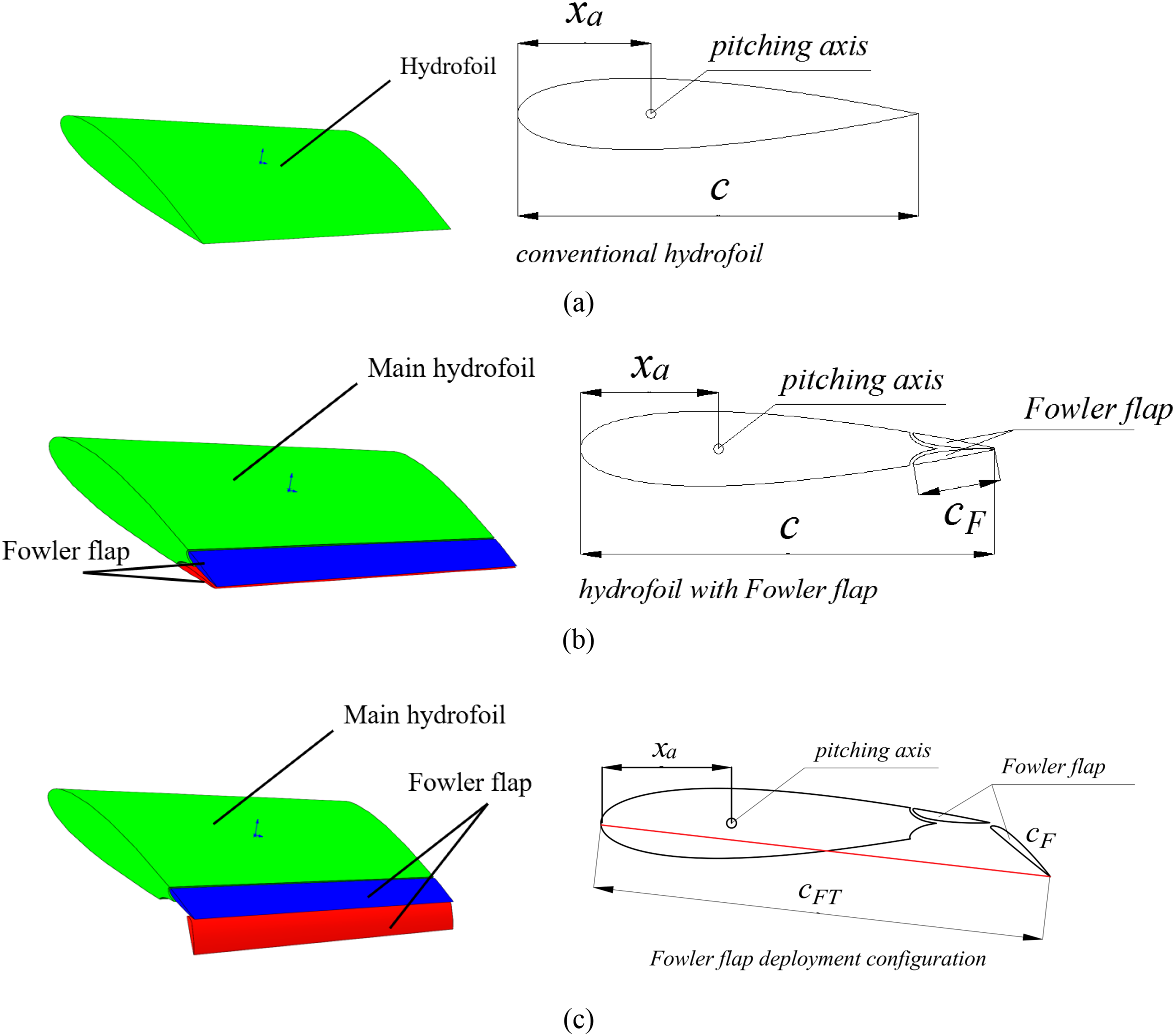
(a–c) Comparison between Fowler oscillating hydrofoil and traditional oscillating hydrofoil.
Fowler flap has a larger lift increment than ordinary single slot flap, and its structure and motion mechanism are simpler than double slot or multi slot flap, which is more conducive to the optimization of lift. It has more and more applications in large civil aircraft.Tian (Tian et al., 2017) studied the aerodynamic characteristics of variable radian Fowler flap through numerical simulation, and found that when the lift coefficient is greater than the critical value, the radian is conducive to improve the lift drag ratio; This critical value is different under different conditions. The takeoff and landing configuration is optimized with 30% chord Fowler flap. DeSalvo (Desalvo et al., 2014; Desalvo et al., 2020) used active aerodynamic flow control to improve the lift of hydrofoil. The hydrofoil uses the structure of Fowler flap and simple flap. This is achieved by driving the spanwise arrangement of fluid oscillating jets upstream and downstream of the leading edge of the flap. These jets increase the flow attachment range along the flap surface under deflection of up to 60°. The driving makes the performance of Fowler flap significantly improved compared with the optimized baseline configuration (the lift coefficient is increased by 30%), and the high lift performance of single element simple flap without cross flow gap can match or exceed the performance of the optimized baseline Fowler configuration. Steinbuch (Steinbuch et al., 2008) introduced the design of double slotted Fowler flaps designed for high-speed acrobatic aircraft. The design of double slotted Fowler flaps is part of the effort to reduce the aircraft’s landing speed, especially when the stall speed is reduced to 90 knots. In the low-speed wind tunnel test, the maximum lift of the target is tested. The increment of the designed Fowler flap to the maximum lift coefficient of the section is about 0.4 larger than the literature value. The stall speed at landing is equal to 90 knots. A multi-objective and multipoint optimization problem is presented by Ernesto Benini dealing with a multi-element hydrofoil used in high-lift devices. The final Pareto Optimal solutions are presented and the reasons for improved performance are discussed (Benini et al., 2011). In Yang’s experiment, particle image velocimetry (PIV) was employed for flow visualization over the upper surface of the flap. The PIV results demonstrate that the flow separation on the flap is suppressed completely by the same DBD actuators used in the simulation (Yang et al., 2016). Van Dam believes that multi-element high-lift system must be as simple and economical as possible while meeting the required aerodynamic performance levels (van Dam, 2002). Bouzaher, MT (Bouzaher et al., 2025) proposes a new type of expandable frontal flap (EFF) to improve power extraction efficiency of a flapping foil, and found that this design is capable of increasing the efficiency by 17% relative to the conventional reversed D-shaped trajectory and by 20% as compared to vertical path.
However, the flaps must have a certain form of movement to ensure the actual operation of the oscillating hydrofoil. This research proposes a Fowler flap that can swing periodically. The movement period of the Fowler flap matches the movement period of the oscillating hydrofoil to ensure that the lift and energy extraction power of the oscillating hydrofoil can be improved. This study deeply analyzed the relationship between the energy extraction efficiency of the oscillating hydrofoil and its geometric and motion parameters, systematically evaluated the influence of the doule Fowler flap on the fluid dynamics and flow structure around the Fowler flap foil, and quantified the energy extraction enhancement effect introduced by the Fowler flap.
2 Numerical modeling and validation
2.1 Structural diagram of flaps
In this study, a movable double Fowler flap is proposed, as seen in Figure 1a shows the hydrofoil structure without Fuller flaps, while Figure 1b shows the hydrofoil structure with Fowler flaps, and Figure 1c shows the state when the Fowler flaps are open. The double Fowler flaps move separately according to the moving direction of the main wing structure, and make the flaps and the main wing form a certain camber. This design ensures that the Fowler flap is always in the most advantageous configuration to generate high lift and high energy harvesting efficient obtained for the system.
The oscillating hydrofoil motion model is defined as the hydrofoil experiencing simultaneously a sinusoidal harmonic heaving motion y(t) and a pitching motion θ(t) under the oncoming flows. Figure 1 depicts the geometric and kinematic parameters of traditional hydrofoil and oscillating hydrofoil with Fowler flap. In order to adapt to the heave movement of the oscillating hydrofoil, the Fowler flap in this paper is divided into two parts, that is, there are two Fowler flaps. The of each Fowler flap performs Fowler motion during lifting and sinking motion respectively. Fowler oscillating hydrofoil is divided into three parts. The first part is defined as the main hydrofoil with subscript m, and the second and third parts are defined as Fowler trailing edge flap with subscript F.
As shown in Figure 1, the chord length of a traditional hydrofoil is c, while in a Fowler flap oscillating hydrofoil, when the flaps are not deployed, the chord length is also c. However, when the flaps are deployed, the chord length changes. According to the definition of chord length, it is the chord length of the line connecting the leading edge point and the trailing edge point of the airfoil, which is the red line part shown in Figure 1c. In this case, the chord length is cFT. The change in chord length will also cause changes in other motion parameters of the hydrofoil. When studying power, it is also necessary to refer to the chord length for calculation. Therefore, in the following calculation formulas, the chord length used in the study of Fowler flaps is cFT.
2.2 The deployment of flaps
Figure 2 shows the unfolding process of the flaps. The flaps translate backwards from position 1, move to position 2, and then rotate to form position 3 in Figure 2. In this state, the hydrofoil has a longer chord length and a larger curvature due to the unfolding of the flaps. According to airfoil theory, a larger airfoil curvature can generate greater lift, thereby promoting the increase of hydrofoil power.
Figure 2
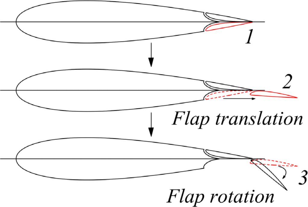
The extension process of Fowler flaps.
In the unfolded structure of hydrofoils, different geometric parameters of Fuller flaps will produce different hydrofoil structures. As shown in Figure 3, this paper selects a parameter combination as the research condition: the translational motion distance of the flaps, F=0.2m, the rotation angle of the flaps, θf =50°, and the chord length of the hydrofoil in this state, cFT 1.13m.
Figure 3
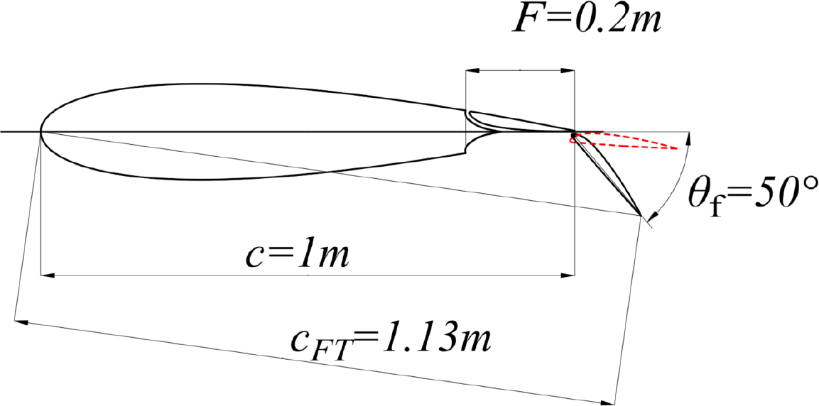
Chord length of Fowler flap oscillating hydrofoil.
2.3 Motion parameters of flaps
The periodic motion of a flapping wing energy harvester can be simplified as the combined periodic motions of heaving y(t) and pitching θ(t), as shown in Figure 4. The heave-pitch oscillating wing motion can be described formally as:
Figure 4
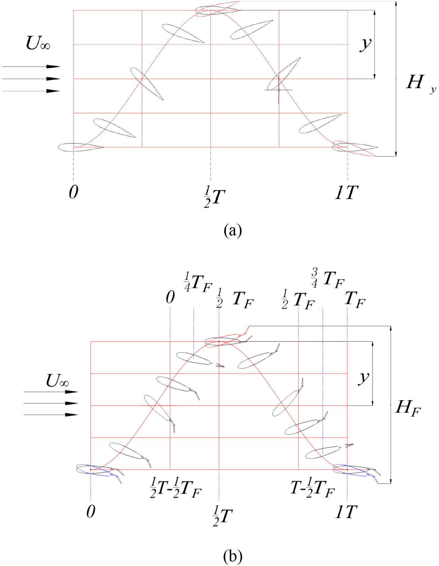
(a, b) A periodic motion form of oscillating hydrofoil with Fowler flap.
where φ is the phase difference between the heaving and pitching motions (φ is kept constant at 90° in this study). In order to unify the calculation, a dimensionless parameter f * is introduced. The reduced frequency f * is defined as , and the heaving velocity is . The minus sign in the formula means that the starting point of the hydrofoil movement is the lowest point. The same is true for pitch amplitude. The cF is the Fowler flap length,
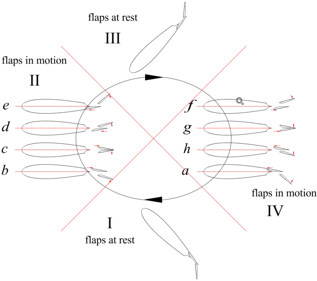
Figure 5 shows the motion mode of Fowler flap. The complete movement of each cycle can be divided into six phases. Each stage can be described as follows:
-
(0~(1/2T-1/2TF)), the main wing moves up and rotates counterclockwise, the Fowler flap remains stationary relative to the main wing;
-
((1/2T-1/4TF)~(1/2T-1/2TF)), the main wing moves up and rotates counterclockwise, the Fowler flap 1 swings counterclockwise relative to the main wing, and moves vertically upward at the same time, at this time, the θf of the Fowler flap 1 becomes smaller, and the slit value S becomes smaller; the Fowler flap 2 performs a horizontal backward movement relative to the main wing, at this time, the Fowler movement amount F of the Fowler flap 2 increases;
-
((1/2T-1/2TF)~(1/2T)), the main wing continues to move up and rotate counterclockwise, and the Fowler flap 1 moves horizontally relative to the main wing. At this time, the Fowler flap 1 moves forward. The Fowler motion F decreases. The Fowler flap 2 swings counterclockwise relative to the main wing, and moves vertically upward at the same time. At this time, the θf of the Fowler flap 2 becomes larger, and the slit value S becomes larger;
-
(1/2T~(T-3/4TF)), the main wing moves down and rotates clockwise, the Fowler flap remains stationary relative to the main wing;
-
(T-TF)~(T-3/4TF), the main wing moves down and rotates clockwise, and the Fowler flap 1 moves horizontally backward relative to the main wing. When the movement amount F increases, the Fowler flap 2 swings clockwise relative to the main wing, and moves vertically downward at the same time. At this time, the θf of the Fowler flap 2 becomes smaller, and the seam value S becomes smaller;
-
((T-3/4TF)~T), the main wing continues to move down and rotate clockwise, the Fowler flap 1 swings clockwise relative to the main wing, and moves vertically downward at the same time. When θF becomes larger, the slit value S becomes larger, and the Fowler flap 2 moves horizontally with respect to the main wing. At this time, the Fowler movement amount F of the Fowler flap 2 is reduced.
Figure 5
Kinematic decomposition diagram of Fowler flap oscillating hydrofoil.
The above movements can be simply summarized as: 1 can be understood as the Fowler flap 1 swings to the maximum position and remains stationary with the main wing swing; 2, 3 can be understood as the Fowler flap 1 starts to retract, the Fowler flap 2 starts Expand. 4 can be understood as the Fowler flap 2 swings to the maximum position and remains stationary with the movement of the main wing, 5 and 6 can be understood as the Fowler flap 1 begins to unfold, and the Fowler flap 2 begins to retract. The motion equation of the Fowler flap is as follows:
In this study, Fowler flap motion cycle TF = 1/8t. The movement time period of Fowler flap is 3/8 T-4/8t and 7/8 T-8/8t.
2.4 Kinetic calculation equation and numerical methodology
The effective angle of attack has a positive relation with the pitching angle. The effective angle of attack is expressed as the combination of the plunging induced and pitching angles (Kinsey and Dumas, 2012; Ma et al., 2017), which can be expressed as follows:
For most oscillating foils in hydrodynamic applications, the pitching axis is located at 1/3 chord length from the leading edge (Young et al., 2014). The corresponding force coefficients CX, CY and moment coefficient CM are defined as follows:
where Fx, Fy and Mz denote, respectively, the lift force, drag force, pitching moment on the foil, and ρ, the fluid density. The instantaneous power extraction P(t) and the time-averaged power denotes can be expressed as follow:
where PL(t) is the instantaneous lift power extraction, PM(t) is the instantaneous moment power extraction, is the time-averaged lift power, is the time-averaged moment power. Furthermore the non-dimensional instantaneous power coefficient Cp(t) and the cycle-averaged power coefficient are denoted by
For a 2D hydrofoil, the swept area S of the oscillating foil equals the overall vertical extent of the foil motion. Therefore, the energy harvesting efficiency η can be defined as:
Figure 6 shows the comparison of sweep height between conventional hydrofoil and Fowler flap hydrofoil. It can be seen intuitively from the Figure 6. that the sweeping height of Fowler flap hydrofoil is higher than that of conventional hydrofoil. H is the sweep height of the convational oscillating hydrofoil, and HF is the sweep height of the oscillating hydrofoil with Fowler flaps. The equation is as follows:
Figure 6
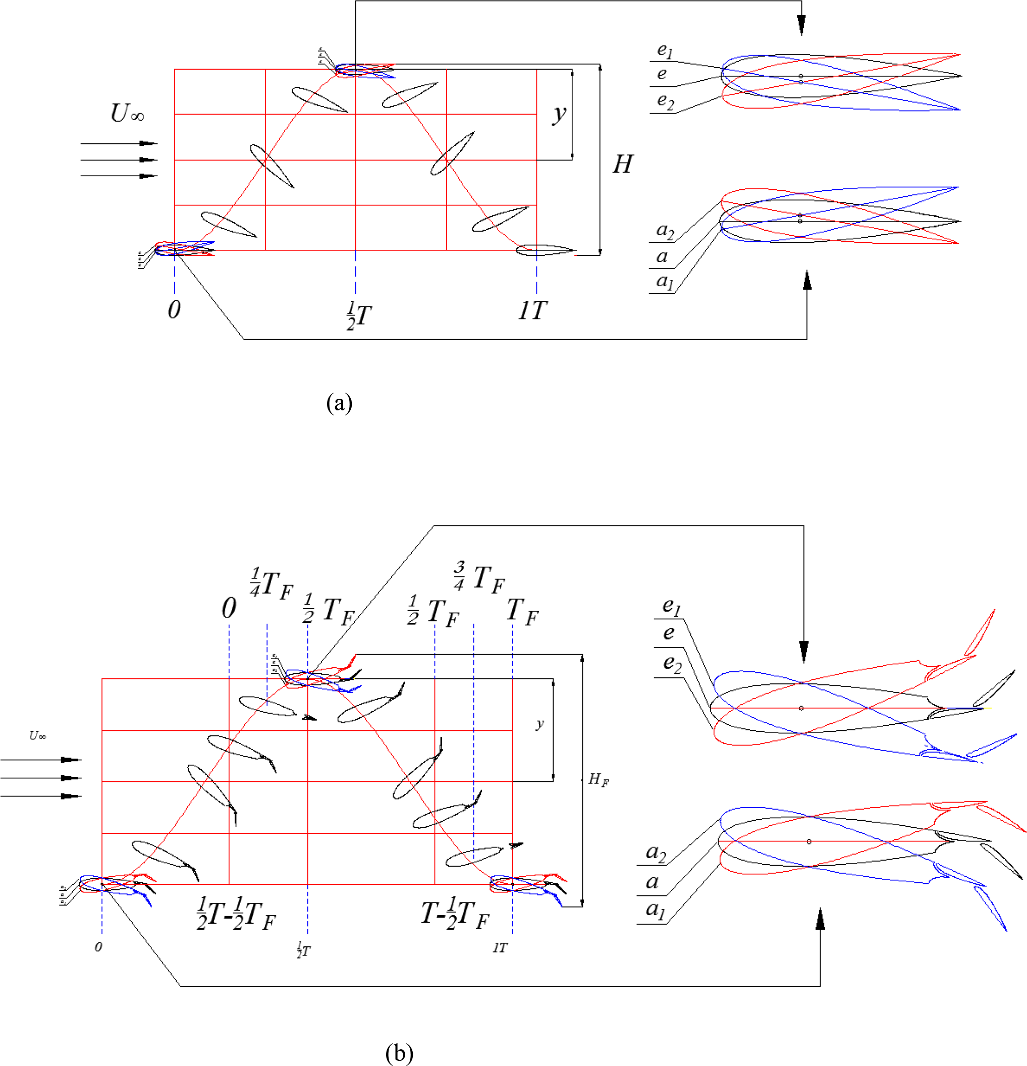
Comparison of sweep height. (a) Sweep height of conventional hydrofoil. (b) Sweep height of Fowler flap.
Figure 7 shows a schematic of the numerical model. The model and method used in this paper are the same as the author’s previous research literature (Sun et al., 2021a; Sun et al., 2021b), so the results can be considered to be correct.
Figure 7
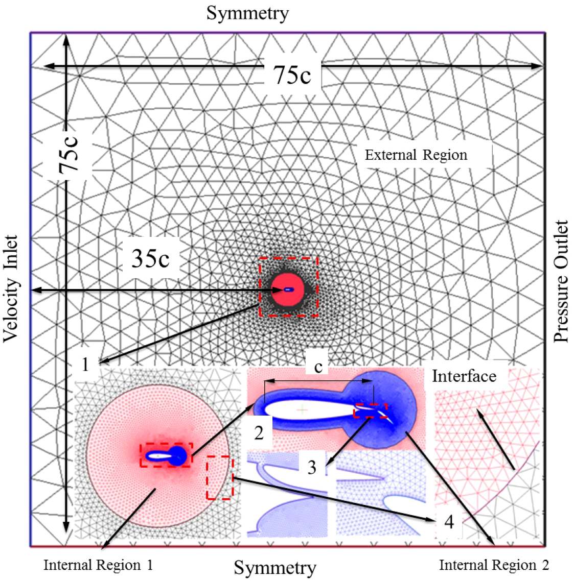
Grid detail and boundary conditions (NACA0018 foil, total cells: 0.9×105,700 nodes on the foil).
3 Results and discussions
All simulations of this study are applied to an NACA0018 foil under equivalent conditions of Re = 2×10⁶, y=c = 1m, cF=0.2m, ρ= 1020kg/m3, U∞ = 2m/s, θ0 = 45°, θF = 50°.
3.1 Comparison of pressure
In Figure 8, this paper compares the external flow field of traditional hydrofoil and Fowler flap hydrofoil. At 0.25T, the attack angle of both hydrofoils is 45°. It can be seen that Fowler flap structure increases the camber of the overall hydrofoil and extends in the chord length direction. These two factors greatly change the stress condition of hydrofoil. The pressure on the lower surface of Fowler flap hydrofoil is higher than that of conventional hydrofoil, and the negative pressure on the upper surface of Fowler flap hydrofoil is also lower than that of conventional hydrofoil. The pressure difference between the two is the lift exerted on the hydrofoil. The greater the pressure difference, the greater the lift exerted on the hydrofoil.
Figure 8
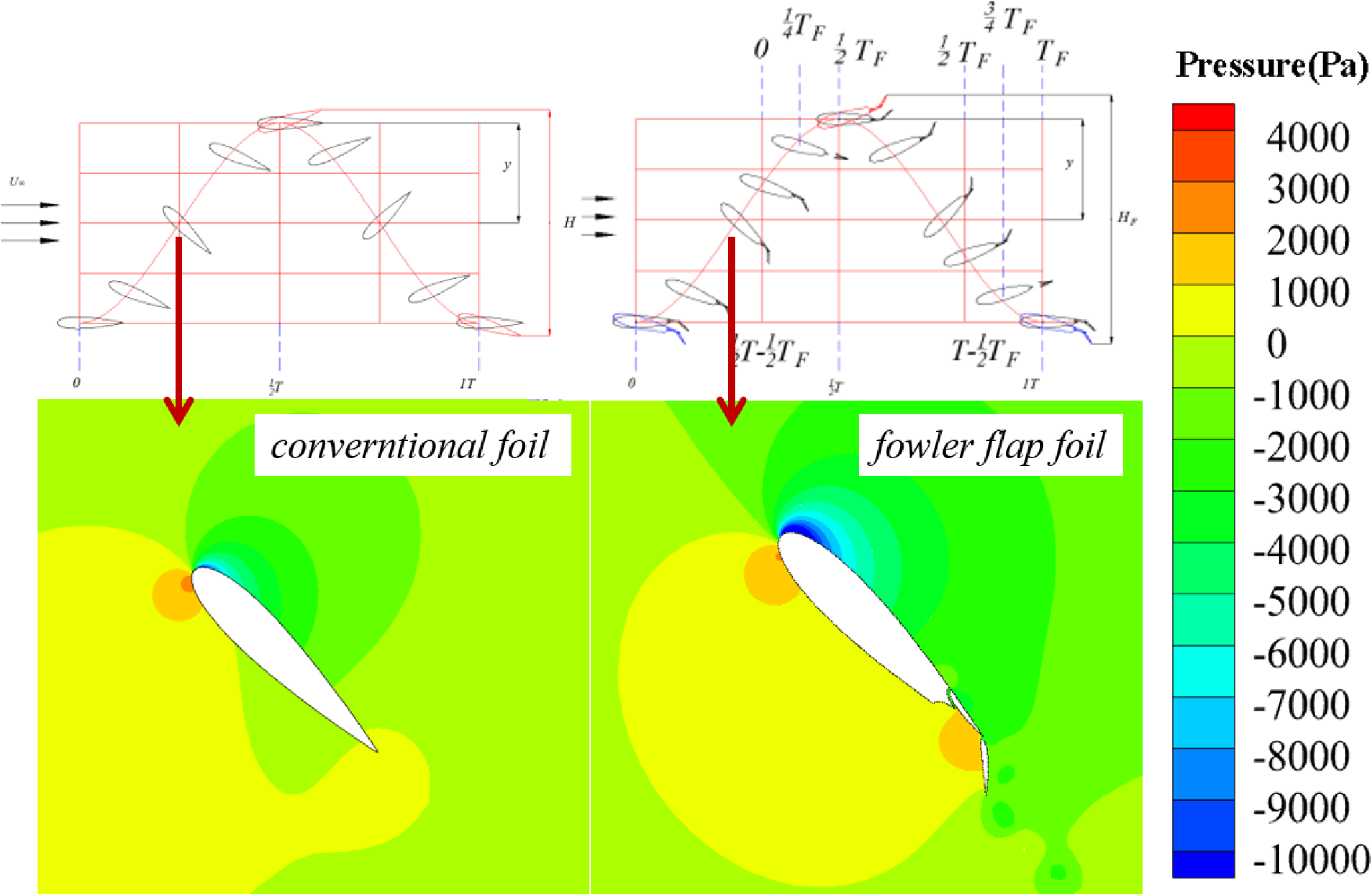
Comparison diagram of flow field pressure distribution at 0.25T.
Figure 9 shows the pressure point distribution around the hydrofoil. Similar to Figure 8, the pressure point of Fowler flap hydrofoil completely wraps the conventional hydrofoil, and the pressure difference between the two Fowler flaps is greater than that of the main wing. It can be seen that the effect of Fowler flap is very obvious.
Figure 9
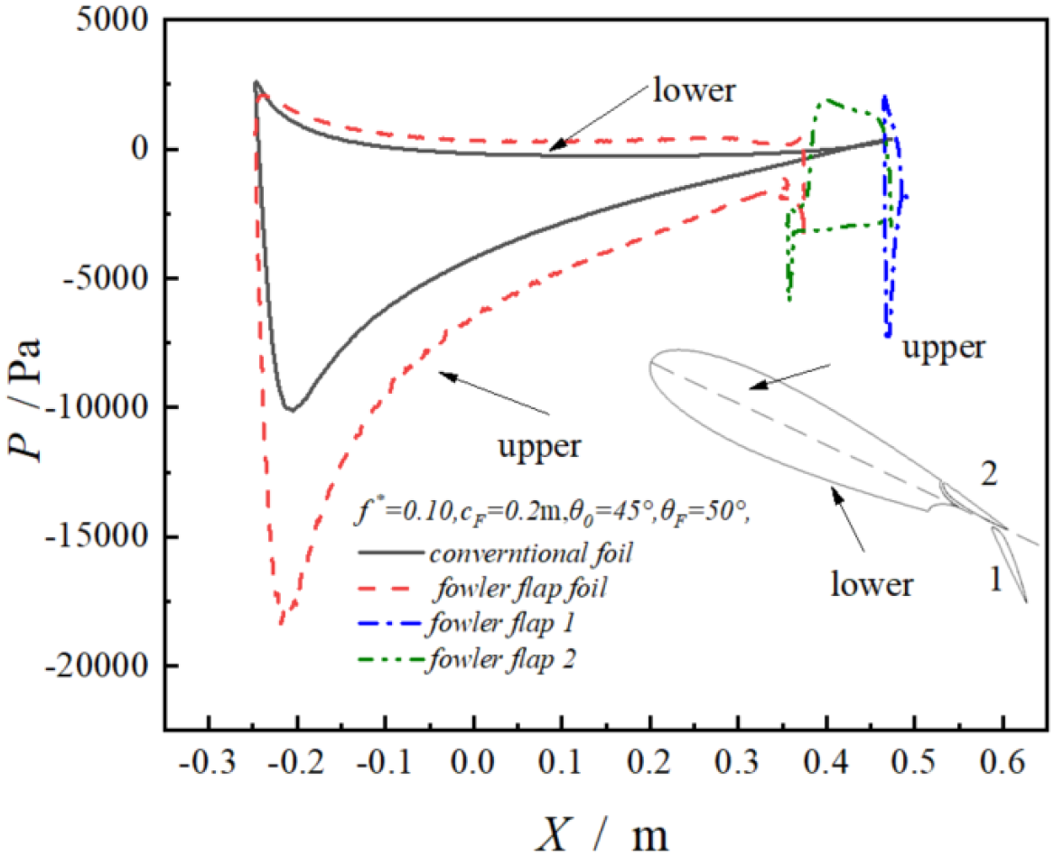
Distribution diagram of hydrofoil pressure points.
3.2 Comparison of vortex
The vortex intensity of Fowler flap hydrofoil is higher than that of conventional hydrofoil. As can be seen from Figures 10, 11, there is almost no vortex shedding on conventional hydrofoils, but vortex shedding occurs on Fowler flap hydrofoils. The reason for the vortex is that the flap structure increases the angle of attack of the original hydrofoil and the chord length of the overall hydrofoil. It can be seen that although Fowler flap structure increases the lift of the overall hydrofoil, it will also produce some bad effects, such as vortices and increased drag. This effect is not expected to be achieved by the structure, and can be optimized on the airfoil of the Fowler flap in the future to achieve the Fowler flap airfoil with the minimum drag and vortex.
Figure 10
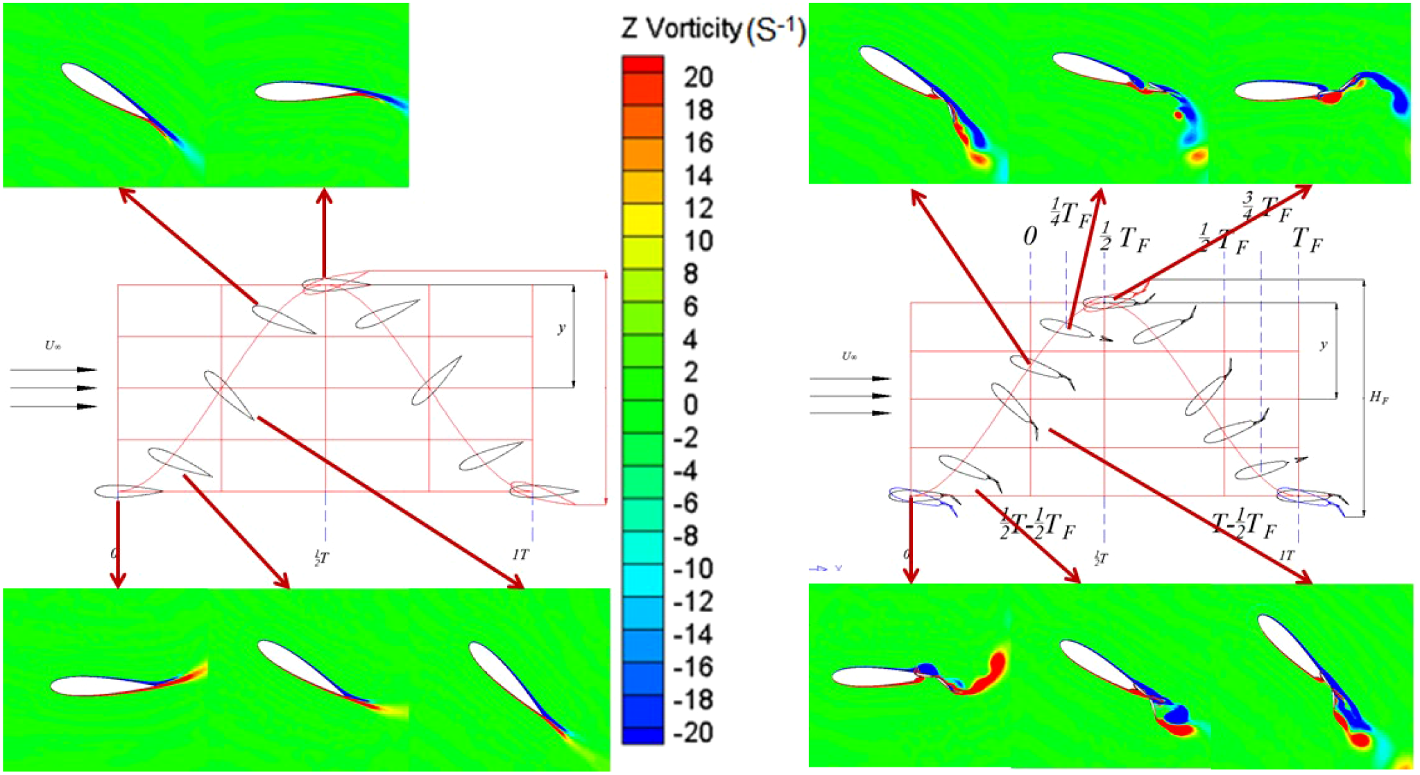
Comparison of vortex distribution of hydrofoil.
Figure 11
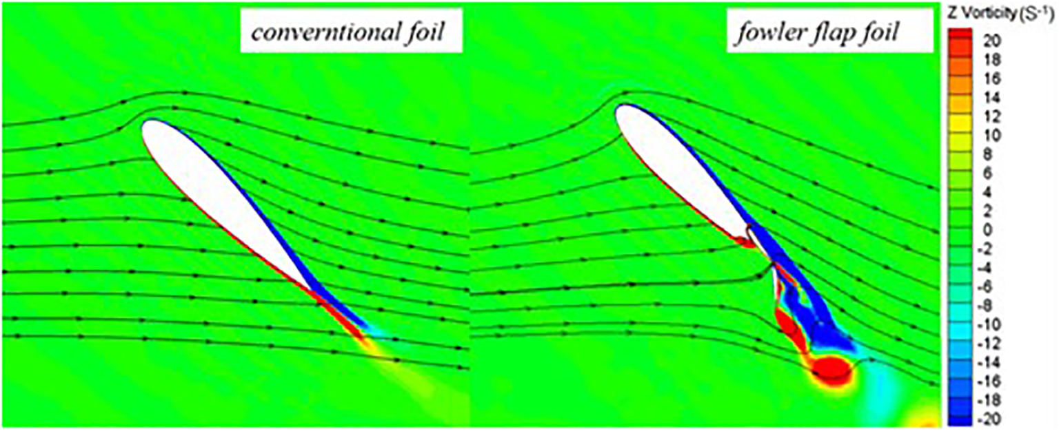
Comparison between vorticity diagram and streamline diagram.
3.3 Comparison of power and hydrodynamics
As can be seen in Figure 12a, The maximum power coefficient of the Fowler flap oscillating hydrofoil is 53%, which is 50% higher than that of traditional hydrofoils. Figure 12a shows that the power curve of Fowler flap is higher than that of conventional flap. Figure 12b shows that the structure of the Fowler flap increases the energy capture efficiency from 14% to 22%. In the movement period of the flap, the absolute value of the negative work of the Fowler flap also increases. In the movement process of the Fowler flap, it pays more negative work than the conventional hydrofoil. Due to the increase of lift coefficient, the overall power is still increased. These changes are reflected in Figure 12c, which shows the trend of power variation during this cycle.
Figure 12
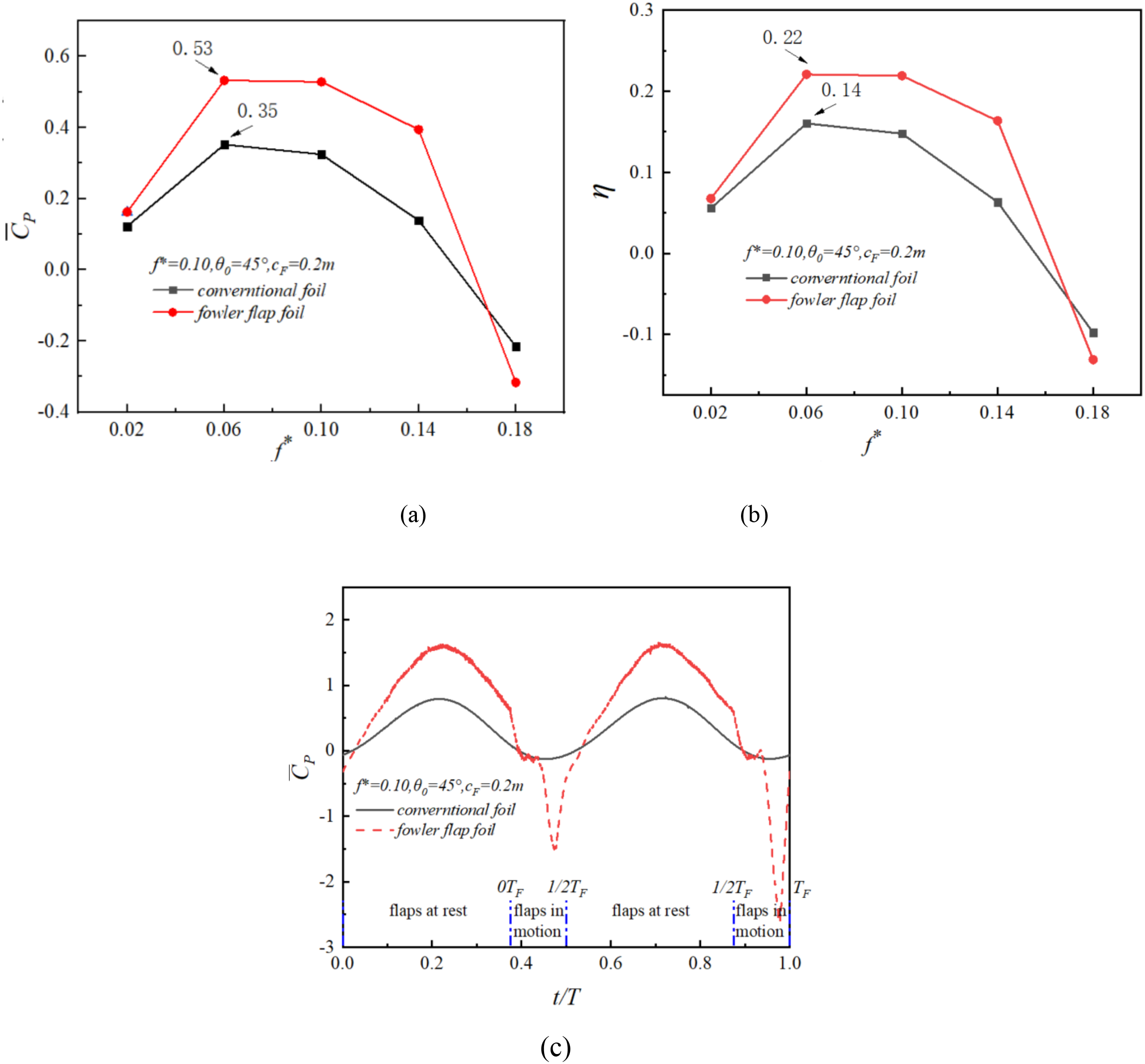
(a–c) Change of power coefficient of Fowler flap oscillating hydrofoil.
Figure 13 shows the variation diagram of hydrodynamic coefficient of Fowler flap in one cycle. When Fowler flap is relatively stationary, the lift coefficient is greatly improved. The drag coefficient curve is consistent with the trend of the lift coefficient, and the overall trend is stable. The lift and drag of the overall hydrofoil only fluctuate during the movement of the flaps. The hydrodynamic curve of the Fowler flap is smooth because the structure of the Fowler flap tends to streamline the entire hydrofoil, with some fluctuations in the wing profile at the trailing edge, which does not have a significant impact on the overall structure of the flap. Fuller flaps are movable flaps, and it is necessary to ensure the overall flow linearity of the airfoil as much as possible in the moving position, which is essential for improving the lift to drag ratio. The design method of the Fuller flap airfoil in this article can be further studied in order to obtain better flap airfoils.
Figure 13
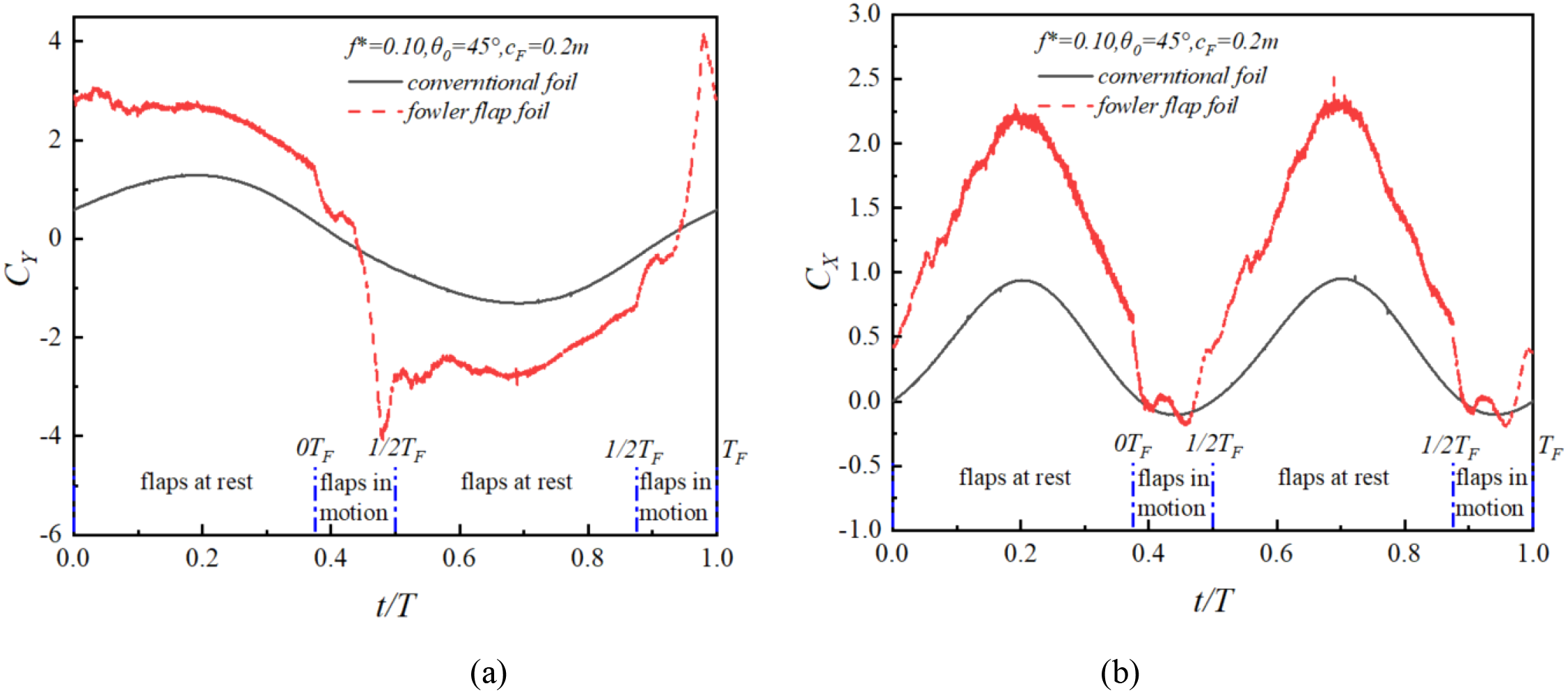
(a, b) Variation of hydrodynamic coefficient of Fowler flap oscillating hydrofoil in one cycle.
4 Conclusions
In the present research, Fowler flap is proposed to improve the energy collection capacity of oscillating hydrofoil, and make the Fowler flap cooperate with the hydrofoil movement. Two dimensional transient numerical simulation of oscillating hydrofoil with conventional foil and Fowler flap is carried out. The simulation results were analyzed comparatively with respect to the energy harvesting efficiency. The results can be summarized as follows.
-
1) Applying the advantages of Fowler flaps to the power generation device of oscillating hydrofoils, a new oscillating hydrofoil structure is proposed based on this, and feasible airfoil structures and motion forms are designed.
-
2) Fowler flap structure can increase the camber and chord length of the integral hydrofoil, and the movement of the Fowler flap is combined with the motion of the oscillating hydrofoil to increase the lift coefficient of the hydrofoil, thus increasing the energy collection efficiency of the oscillating hydrofoil, the maximum increase is 50%.
-
3) The structure of Fowler flap makes the overall hydrofoil smooth. In the structure of this article, the fluctuation of lift and drag of oscillating hydrofoil is very small. The overall smoothness is similar to that of conventional hydrofoil, but the lift and resistance are greatly improved.
Statements
Data availability statement
The original contributions presented in the study are included in the article/supplementary material. Further inquiries can be directed to the corresponding author.
Author contributions
GS: Writing – original draft, Writing – review & editing, Conceptualization, Data curation, Formal analysis, Investigation. QZ: Conceptualization, Data curation, Writing – review & editing. HS: Conceptualization, Data curation, Writing – review & editing. MC: Conceptualization, Software, Writing – review & editing. GL: Methodology, Software, Writing – review & editing.
Funding
The author(s) declare financial support was received for the research and/or publication of this article. The authors gratefully acknowledge the support of the National Natural Science Foundation of China [No. 51875316], the Natural Science Foundation of Shandong Province [ZR2019MEE025].
Conflict of interest
The authors declare that the research was conducted in the absence of any commercial or financial relationships that could be construed as a potential conflict of interest.
Generative AI statement
The author(s) declare that no Generative AI was used in the creation of this manuscript.
Publisher’s note
All claims expressed in this article are solely those of the authors and do not necessarily represent those of their affiliated organizations, or those of the publisher, the editors and the reviewers. Any product that may be evaluated in this article, or claim that may be made by its manufacturer, is not guaranteed or endorsed by the publisher.
Glossary
- c
chord length of the oscillating hydrofoil
- cF
length of the Fowler flap
- cFT
length of the Fowler flap hydrofoil
- Fx
lift force
- Fy
drag force
- Mz
pitching moment
- CX
non-dimensional drag coefficient in horizontal direction
- CY
non-dimensional lift coefficient in vertical direction
- CM
pitching moment coefficient
average power coefficient
- CPY
power coefficient of heave motion (CPY )
- CPM
power coefficient of pitching motion (CPM)
- T
hydrofoil motion period
- θ
pitching amplitude
- f
hydrofoil frequency (=1/T)
- f *
non-dimensional frequency (f*=fc/U∞)
- H0
sweep area of the oscillating hydrofoil
- HF
sweep area of the oscillating hydrofoil with Fowler flap
- η
energy harvesting efficiency
- P
hydrofoil pressure
- Re
Reynolds number
- U∞
freestream velocity
- X
the coordinate of hydrofoil in X axis
- t
current time.
References
1
Ashraf M. A. Young J. Lai J. C. S. Platzer M. F. (2011). Numerical analysis of an oscillating-wing wind and hydropower generator. AIAA J.49, 1374–1386. doi: 10.2514/1.J050577
2
Balduzzi F. Drofelnik J. Bianchini A. Ferrara G. Ferrari L. Campobasso M. S. (2017). Darrieus wind turbine blade unsteady aerodynamics: a three-dimensional Navier-Stokes CFD assessment. Energy128, 550–563. doi: 10.1016/j.energy.2017.04.017
3
Benini E. Ponza R. Massaro A. (2011). High-lift multi-element airfoil shape and setting optimization using multi-objective evolutionary algorithms. J. Aircraft.48, 683–696. doi: 10.2514/1.C031233
4
Bouzaher M. T. Zereg A. Nora B. Eddine B. D. Lebaal N. (2025). Numerical research on the effect of expandable flaps on the output power of flapping foils. J. Braz. Soc. Mechanical Sci. Engineering.47, 242–242. doi: 10.1007/s40430-025-05545-6
5
Desalvo M. Whalen E. Glezer A. (2014). Enhancement of a Fowler flap high-lift system using active flow control. doi: 10.2514/masm14
6
Desalvo M. Whalen E. Glezer A. (2020). High-lift performance enhancement using active flow control. AIAA J.58, 4228–4242. doi: 10.2514/1.J059143
7
Khan M. J. Bhuyan G. Iqbal M. T. Quaicoe J. E. (2009). Hydrokinetic energy conversion systems and assessment of horizontal and vertical axis turbines for river and tidal applications: A technology status review. Appl. Energy.86, 1823–1835. doi: 10.1016/j.apenergy.2009.02.017
8
Kinsey T. Dumas G. (2008). Parametric study of an oscillating airfoil in a power-extraction regime. AIAA J.46, 1318–1330. doi: 10.2514/1.26253
9
Kinsey T. Dumas G. (2012). Computational fluid dynamics analysis of a hydrokinetic turbine based on oscillating hydrofoils. J. Fluids Engineering.134, 21104. doi: 10.1115/1.4005841
10
Kinsey T. Dumas G. Lalande G. Ruel J. Méhut A. Viarouge P. et al . (2011). Prototype testing of a hydrokinetic turbine based on oscillating hydrofoils. Renewable Energy.36, 1710–1718. doi: 10.1016/j.renene.2010.11.037
11
Kusiak A. Zhang Z. Verma A. (2013). Prediction, operations, and condition monitoring in wind energy. Energy60, 1–12. doi: 10.1016/j.energy.2013.07.051
12
Lam W. Chen L. Hashim R. (2015). Analytical wake model of tidal current turbine. Energy79, 512–521. doi: 10.1016/j.energy.2014.11.047
13
Liu Z. Wang Y. Hua X. (2020). Numerical studies and proposal of design equations on cylindrical oscillating wave surge converters under regular waves using SPH. Energy Conversion Management.203, 112242. doi: 10.1016/j.enconman.2019.112242
14
Ma P. Wang Y. Xie Y. Zhang J. (2018). Analysis of a hydraulic coupling system for dual oscillating foils with a parallel configuration. Energy143, 273–283. doi: 10.1016/j.energy.2017.10.141
15
Ma P. Wang Y. Xie Y. Han J. Sun G. Zhang J. (2019). Effect of wake interaction on the response of two tandem oscillating hydrofoils. Energy Sci. Engineering.7, 431–442. doi: 10.1002/ese3.286
16
Ma P. Yang Z. Wang Y. Liu H. Xie Y. (2017). Energy extraction and hydrodynamic behavior analysis by an oscillating hydrofoil device. Renewable Energy.113, 648–659. doi: 10.1016/j.renene.2017.06.036
17
Mckinney W. Delaurier. J. (1981). WINGMILL: AN OSCILLATING-WING WINDMILL. J. energy.5, 109–115. doi: 10.2514/3.62510
18
Neill S. P. Angeloudis A. Robins P. E. Walkington I. Ward S. L. Masters I. et al . (2018). Tidal range energy resource and optimization – Past perspectives and future challenges. Renewable Energy.127, 763–778. doi: 10.1016/j.renene.2018.05.007
19
Rourke F. O. Boyle F. Reynolds A. (2010). Tidal energy update 2009. Appl. Energy.87, 398–409. doi: 10.1016/j.apenergy.2009.08.014
20
Steinbuch M. Marom S. Gabriel E. Koshorok A. (2008). Aerodynamic design of double-slotted Fowler flap for acrobatic aircraft Javelin. 2, 653–672.
21
Sun G. Wang Y. Xie Y. Ma P. Zhang Y. (2021a). Research on the effect of a movable gurney flap on energy extraction of oscillating hydrofoil. Energy (Oxford).225, 120206. doi: 10.1016/j.energy.2021.120206
22
Sun G. Wang Y. Xie Y. Ma P. Zhang Y. (2021b). Hydrodynamic and energy extraction properties of oscillating hydrofoils with a trailing edge flap. Appl. Ocean Res.110, 102530. doi: 10.1016/j.apor.2021.102530
23
Tian Y. Wang T. Liu P. Feng P. (2017). Aerodynamic/mechanism optimization of a variable camber Fowler flap for general aviation aircraft. Sci. China Technological Sci.60, 1144–1159. doi: 10.1007/s11431-016-0218-5
24
Uihlein A. Magagna D. (2016). Wave and tidal current energy – A review of the current state of research beyond technology. Renewable Sustain. Energy Rev.58, 1070–1081. doi: 10.1016/j.rser.2015.12.284
25
van Dam C. P. (2002). The aerodynamic design of multi-element high-lift systems for transport airplanes. Prog. aerospace Sci.38, 101–144. doi: 10.1016/S0376-0421(02)00002-7
26
Xiao Q. Liao W. Yang S. Peng Y. (2012). How motion trajectory affects energy extraction performance of a biomimic energy generator with an oscillating foil? Renewable Energy.37, 61–75. doi: 10.1016/j.renene.2011.05.029
27
Xu J. Sun H. Tan S. (2016). Wake vortex interaction effects on energy extraction performance of tandem oscillating hydrofoils. J. Mechanical Sci. Technology.30, 4227–4237. doi: 10.1007/s12206-016-0835-9
28
Yang L. Li J. Cai J. Wang G. Zhang Z. (2016). Lift augmentation based on flap deflection with dielectric barrier discharge plasma flow control over multi-element airfoils. J. fluids Eng.138, 3–10. doi: 10.1115/1.4031613
29
Young J. Lai J. C. S. Platzer M. F. (2014). A review of progress and challenges in flapping foil power generation. Prog. Aerospace Sci.67, 2–28. doi: 10.1016/j.paerosci.2013.11.001
30
Zhang Y. Wang Y. Xie Y. Sun G. Han J. (2022). Effects of flexibility on energy extraction performance of an oscillating hydrofoil under a semi-activated mode. Energy242, 122940. doi: 10.1016/j.energy.2021.122940
31
Zhang D. Ma X. Si Y. Huang C. Huang B. Li W. (2017). Effect of doubly fed induction generatorTidal current turbines on stability of a distribution grid under unbalanced voltage conditions. Energies10, 212. doi: 10.3390/en10020212
Summary
Keywords
tidal energy, oscillating hydrofoil, Fowler flap, energy harvesting, hydrodynamic
Citation
Sun G, Zhang Q, Sun H, Chi M and Liu G (2025) Hydrodynamic and energy extraction properties of oscillating hydrofoil with double Fowler flaps. Front. Mar. Sci. 12:1651862. doi: 10.3389/fmars.2025.1651862
Received
22 June 2025
Accepted
23 July 2025
Published
25 August 2025
Volume
12 - 2025
Edited by
Zhigang Zhang, Shandong University, China
Reviewed by
Penglei Ma, Ocean University of China, China
Yubing Zhang, Qilu Normal University, China
Hui Chen, Qilu University of Technology, China
Updates
Copyright
© 2025 Sun, Zhang, Sun, Chi and Liu.
This is an open-access article distributed under the terms of the Creative Commons Attribution License (CC BY). The use, distribution or reproduction in other forums is permitted, provided the original author(s) and the copyright owner(s) are credited and that the original publication in this journal is cited, in accordance with accepted academic practice. No use, distribution or reproduction is permitted which does not comply with these terms.
*Correspondence: Guang Sun, sunguang123@126.com
Disclaimer
All claims expressed in this article are solely those of the authors and do not necessarily represent those of their affiliated organizations, or those of the publisher, the editors and the reviewers. Any product that may be evaluated in this article or claim that may be made by its manufacturer is not guaranteed or endorsed by the publisher.