 M. Ojha1,2
 S. N. Bhukya
 Z. Wu
Z. Wu A. A. Elmustafa
- 1Department of Mechanical and Aerospace Engineering, Old Dominion University, Norfolk, VA, United States
- 2The Applied Research Center-Thomas Jefferson National Accelerator Facility, Newport News, VA, United States
- 3Department of Engineering, Virginia State University, Petersburg, VA, United States
Friction stir welding of high-strength materials such as steels is the impeded by the lack of the vast heat input needed to start the process. Contact friction is considered the most dominant source of heat generation for FSW steels which tends to cause severe wear conditions of the tool hear. To relieve the extreme wear conditions that occur on the tool heads because of FSW steels, we introduce the non-mixing Cu donor stir material to friction stir welding of aluminum alloys. The elastic properties of the Cu donor assisted friction stir welded aluminum alloys are measured using nanoindentation. The hardness and elastic modulus were measured for two regions, the base metal (BM) and the stir zone (SZ). The measurements were conducted for 20% and 60% Cu non-heat treated (NHT) and heat-treated (HT) samples. The nanomechanical properties were measured using nanoindentation with the continuous stiffness method (CSM) in depth control. The HT samples are softer than the NHT samples as expected. However, the 20% Cu NHT and HT samples depicted the same hardness at the SZ. Similar results were observed for the 60% Cu donor stir samples. It therefore concluded that the SZ is softer than the BM for the 20% and 60% Cu donor stir material as expected. The hardness of the weld at the SZ is similar to the hardness of the Al6061-T6 plate, suggesting that the Cu donor stir material did not impact the hardness properties of the Al6061-T6 plate due to the depletion of the Cu donor stir material during the welding process, an important result of the concept of the donor material. The elastic moduli of the Cu donor stir welded samples vary between
1 Introduction
Friction Stir Welding (FSW) technology combines heat input from friction and extreme plastic deformation to produce high-quality joints in aluminum and other alloy systems (Haghshenas and Gerlich, 2018; Cabibbo et al., 2020; Chen et al., 2020; Wang et al., 2020; Ahmed et al., 2021). The technology has been successful in low melting temperatures and low-strength materials such as aluminum and aluminum alloys. However, it needs to be more practical for high-strength materials such as carbon steel, stainless steel, and other metals with relatively high melting temperatures. To date, much of the work on FSW has relied on empirical, trial and error methods to obtain an understanding of the process (Shi et al., 2015; Haghshena and Gerlich, 2018; Gao et al., 2019; Hossfeld, 2022). While the FSW technology advances, fundamental processes such as interacting heat sources, coupling between thermal and mechanical interactions, and developing grain structure and precipitate morphology in the weld zone still need to be understood entirely. There is a need to predict the effect of welding parameters and tool geometry on the temperature, strain fields, and the resulting weld microstructure to obtain significant advances beyond the current state of the FSW technology. One of the challenges for friction stir welding high-strength materials such as steels is the immense heat input needed to start the process (Mandal et al., 2013; Rice et al., 2014). Although contact friction is the dominant heat source for FSW steels, this tends to result in severe wear conditions on the FSW tool (Bousquet et al., 2011; Sahlot et al., 2018; Majeed et al., 2021; Hasieber et al., 2022; Zuo et al., 2022). To mitigate the extreme wear conditions that occur on the tool heads because of FSW steels, some researchers relied more on expensive tool heads such as tungsten carbide, tungsten rhenium alloys, and, more recently, polycrystalline cubic boron nitride (PCBN) tools (Shah and Warke, 2017; Adesina et al., 2018). Other researchers considered heat management alternatives (Mandal et al., 2013; Rice et al., 2014; Maniscalco et al., 2022). Mandal, Rice, Hou, Williamson, and Elmustafa considered a heat management approach that emphasizes recursive plastic heating (RPH). As a fundamental mechanism that operates within the FSW region and provides most of the heat needed to sustain the process. Recently, a thorough numerical (Maniscalco et al., 2022) and experimental (Bhukya et al., 2022) investigation was performed to understand the fundamental interface mechanisms that influence interactions between the tool pin, tool shoulder, and surrounding material flow in the workpiece copper donor material-assisted friction stir welding (FSW) of AA6061-T6 alloy. Cu-assisted FSW joints of AA6061-T6 alloy were prepared at a constant tool rotational rate of 1,400 rpm and welding speeds of 1 and 3 mm/s, respectively. The Cu donor material was selected due to its high thermal conductivity and low hardness/modulus ratio as compared to the AA6061-T6 alloy.
In this research, we measure the elastic properties of the donor assisted friction stir welded aluminum alloys using nanoindentation equipped with the continuous stiffness method (CSM) in depth control. The hardness and elastic modulus were measured for two regions, the BM and the SZ regions. The measurements were conducted for the 20% and 60% Cu solution-treated, six- and 24-h heat-treated samples.
2 Experimental detail
2.1 Samples’ fabrication
FSW samples of AA6061-T6 aluminum alloy with 20% and 60% Cu donor assisted material were fabricated. The Cu donor assisted material represent 20% and 60% of the workpiece thickness. The Cu donor assisted material is intended to support the FSW joining at the plunge stage. Post-weld analysis was characterized in terms of microstructure and mechanical properties. Figure 1 demonstrates schematic illustration of the FSW samples mounted on epoxy puck. The figure depicts Al6061-T6 base metal, 20% and 60% Cu donor materials respectively. The tested samples included 20% and 60% donor stir material solution treated (ST), and non-heat treated (NHT). The samples were solution treated at 540°C for 1 h followed by quenching in the water at room temperature and then further artificially aged at 180°C for 24 h followed by air cooling Table 1 illustrates the different samples designation. More details about the samples fabrication process can be found in Bhukya et al. (2023).
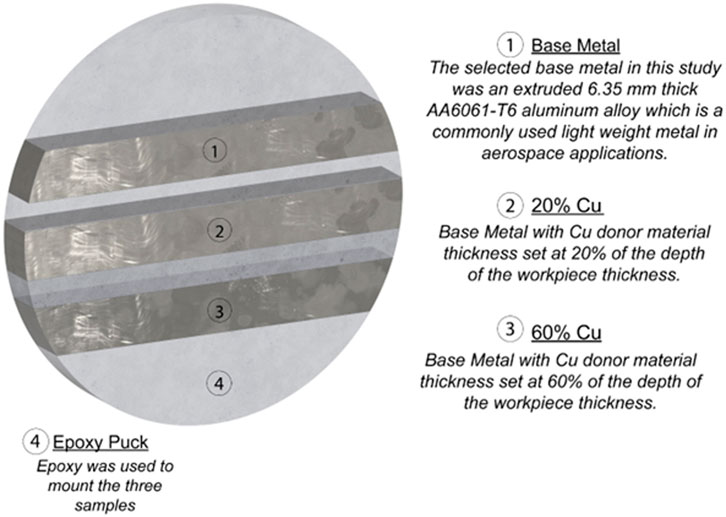
FIGURE 1. Schematic Illustration of FSW samples mounted on the epoxy puck.
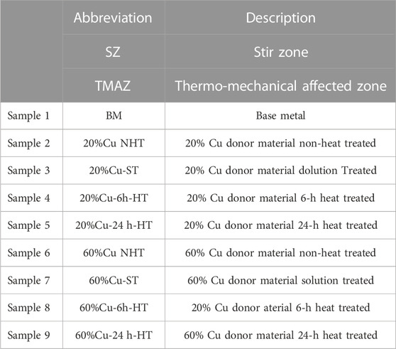
TABLE 1. Abbreviations and samples’ designation.
2.2 X-ray diffraction and scanning electron microscopy with energy dispersive spectroscopy
For X-ray diffraction (XRD) measurement, a Bruker-AXS three-circle diffractometer, equipped with a SMART Apex II CCD detector and graphite-monochromated CuKα radiation were used. The morphology of the films was examined using a JEOL JSM-6060 LV scanning electron microscope-energy dispersive spectroscopy (SEM-EDS). The SEM-EDS was operated at an accelerating voltage of 30 kV.
2.3 Indentation testing
To measure the elastic properties of the FSW samples, indentation tests were carried out using an XP nanoindenter equipped with a continuous stiffness method (CSM). The CSM technique produces the evolution of hardness and elastic modulus as a continuous function of penetration depth into the surface by superimposing a small harmonic force oscillation (usually resulting in a harmonic displacement oscillation of 2 nm or less) on the tip during the loading cycle. This allows the stiffness of contact, and consequently the mechanical properties of the sample to be continuously evaluated by analyzing the harmonic force and harmonic displacement data, as detailed in (Oliver and Pharr, 2004). The indentation tests were carried out in depth and load control modes to a maximum depth of indentation of
3 Results and discussion
Figure 2 shows the XRD patterns of the FSW donor stir materials prepared at different percentages of Cu, solution treated, non-heat treated, and 24 h heat treated samples. The diffraction peaks of the FSW donor stir materials, Cu 110 alloy, and the Al6061-T6 base material are labeled in the figure. XRD diffraction of the FSW donor stir materials exhibits crystallographic planes of (111), (200), (220), (311), and (222) orientations at 38.1°, 44.4°, 64.8°, 77.9°, and 82.1° phase angles. The Cu donner material shows characteristic peaks of pure Cu (bottom black line) at 45°, 54.5°, and 83.6°, corresponding to Cu (111), Cu (200), and Cu (220), respectively. As the Cu donor stir material percentage increases the degree of crystallinity of the FSW donor stir material increases as well. It is noted that the 20% and 60% Cu donor stir material resulted in the same orientations of the AA 6061-T6 alloy. It is also observed that regardless of the percentage of the Cu donor stir material and heat treatment the phases of the FSW samples are the same as of the AA6061-T6 alloy, an important result that indicated the Cu donor stir material does not impact the final welded joint. The presence of the Cu donor stir material in the final welded joint, if any, will result in an inhomogeneous weld. The reflections of the orientations (111), (200), and (220) of thecubic FSW phase were present at the initial Al-6061-T6 with highest intensities at 38.1°, 44.4°, 64.8°, and the (311) orientation at 77.9° for the 20% Cu solution treated sample. Literature reports indicate the formation of cubic phases of Cu at 38.1° and 44.4° of Cu Al O2 (Reference code: 96-153-7363) (Gražulis et al., 2009; Gražulis et al., 2015; Merkys et al., 2016; Quirós et al., 2018).
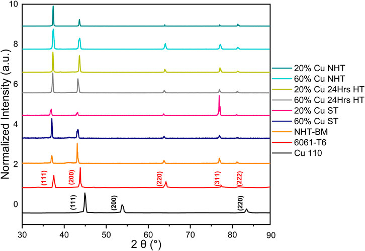
FIGURE 2. XRD patterns of FSW donor stir materials with different levels of Cu, solution treated, non-heat treated, and 24 h heat treated samples.
The results of this figure suggest that the orientations of the 20%, 60% solution treated, non-heat treated, and heat treated FSW donor stir samples are identical to the orientation of the Al6061-T6 base material. The mixture of the Cu donor material with the Al6061-T6 base material would have adversely resulted in an inhomogeneous weaker weld. However, the Cu donor stir material was completely washed away during the welding process leaving the Al6061-T6 base material intact. This is considered an important result which suggests that the donor Cu stir material is not mixed with the finished FSW welded samples of the Al6061-T6 material. The characteristics of the chemical composition of the FSW donor stir samples as impacted by the Cu stir donor material percentage was examined by SEM-EDS.
Figure 3 shows the SEM image, point and line spectrum EDS analysis of the NHT Al6061-T6 alloy samples with 20% Cu at the SZ. The dotted line on the SEM image shows the 50 points along which the line scan was performed. The element counts of aluminum and other materials are consistent along all the points except the points along the indents due to lower scan volume. The 12th point along the line was taken for point analysis. 88.08% of Al by weight was detected along with 3.35% C, 3.18% O, 4.48% Mg, and 0.91% Si. Figure 4 shows the EDS area mapping of the 20% Cu NHT sample at the SZ across a surface area of 330 × 450 μm2. The densely distributed aluminum is shown in red, while other elements (C, O, Mg, and Si) are sparsely distributed along the surface. Figure 5 shows a 5 µm deep indent in the SZ of a 20% Cu donor stir material NHT sample. The EDS line spectrum analysis represents 50 points along the indent. The Al spectrum of all the 50 points represented by different colors along the indent is similar suggesting that the chemical composition of the welded sample at various depths is identical to the surface. The weight% distribution for all 50 points was similar to the 12th point discussed above (other materials are not seen in the figure due to low intensity). No traces of Cu were detected in the point analysis, line analysis, and area mapping along the surface and indent of the 20% Cu NHT Al6061-T6 alloy. Figure 6 depicts the EDS point analysis plot of the FSW 20%, 60% Cu solution treated, non-heat treated, six- and 24-h heat-treated samples. Three separate regions were selected for the SEM-EDS sample characterization, left (or BM), middle (or SZ), and right (also BM). All three regions generated similar EDS results and we opted to show results of the middle (SZ) and the right (BM). Although we only show Al peaks in the figure, other elements were also present, but in very small insignificant sizes. It was not possible to represent these elements with peaks in the figure due to their incomparable sizes. All the samples at both SZ and BM generated similar EDS results as discussed above for the 20% Cu NHT sample. It is obvious that Al is the predominant element while other elements exist but with very low intensity. It can also be noticed that the Cu donor material was not detected as expected.
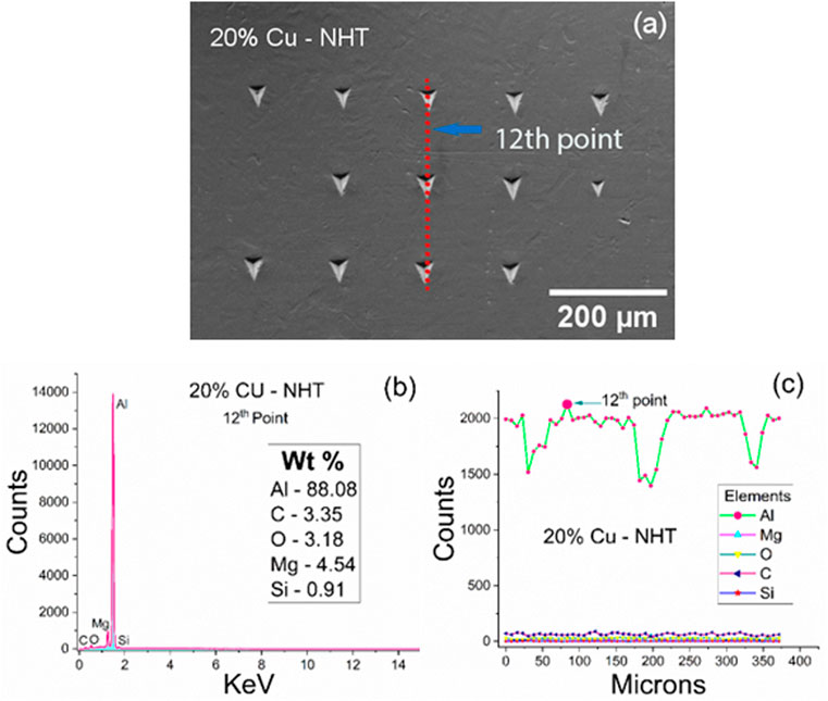
FIGURE 3. (A) SEM image and EDS graph of 20% Cu NHT Al6061-T6 alloy sample at the SZ. (B) Point spectrum. (C) Line spectrum.
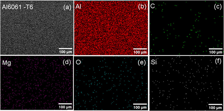
FIGURE 4. (A) EDS spectral analysis for the elemental composition of 20% Cu NHT Al6061-T6 alloy sample at the SZ. The breakdown of the elements distribution is as follows: of (B) Al (88.08%). (C) C (3.35%). (D) Mg (4.54%). (E) O (3.18%). (F) Si (0.91%).
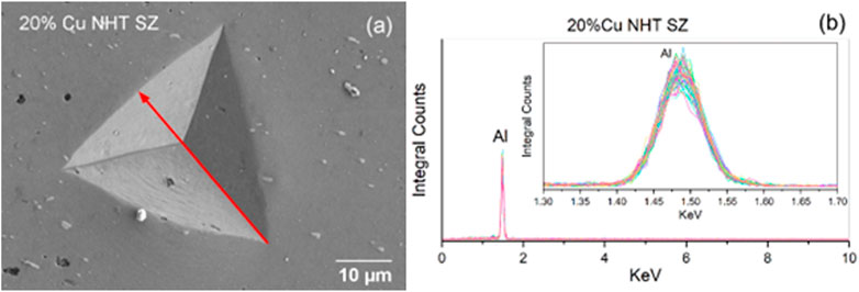
FIGURE 5. (A) Nanoindentation of 20% Cu NHT Al6061-T6 alloy sample at SZ. (B) EDS line spectrum of 50 points along the indent.
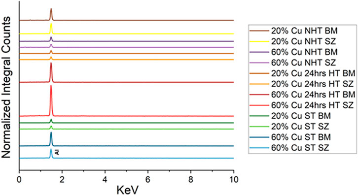
FIGURE 6. EDS plot of FSW samples with 20% and 60% Cu NHT, 24-h HT, and ST Al6061-T6 alloy samples at SZ and BM respectively.
An illustration of a load-depth from XP tests is presented for 60% Cu NHT samples as shown in Figure 7. The data represent an average of 20 indents. For visual clarity, only CSM depth control test data are presented. The total depth of penetration is
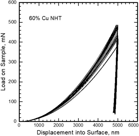
FIGURE 7. Load-depth of 60%Cu NHT samples.
The hardness versus depth of indentation is plotted in Figure 8 for the 20% and 60% Cu NHT and HT samples. The data are plotted for the BM where the BM represents the locations at the right and left of the sample away from the middle of the sample which represents the SZ. The hardness increases with a decrease in the depth of indentation from an average hardness value of 1.13 GPa at a depth of indentation of 4,155 nm to an average hardness of 1.73 GPa at a depth of indentation of 185 nm for the NHT. Similar results were also observed for 60% Cu donor material NHT samples where the hardness increases from 0.87 GPa at a depth of indentation of 4,680 nm to a hardness value of 1.18 GPa at a depth of indentation 316 nm. The HT samples depicted the same behavior. The hardness increases from 0.69 GPa at a depth of indentation of 4,699 nm to a hardness value of 0.92 GPa at depth of indentation of 260 nm for the 20% Cu donor stir HT samples. The hardness also increases from 0.61 GPa at a depth of indentation of 4,699 nm to a hardness value of 1.06 GPa a depth of indentation of 260 nm for the 60% Cu donor stir HT samples. Therefore, the 20%, 60% Cu NHT, and HT stir donor material samples exhibit an ISE typical of the Al6061-T6 alloy. The increase in hardness with the decrease in the indentation depth is known in the literature as the indentation size effect (ISE) (Elmustafa and Stone, 2002; Elmustafa and Stone, 2003; Stegall et al., 2012; Stegall and Elmustafa, 2018). The ISE is commonly observed in aluminum and aluminum alloys. It is obvious that the HT samples are softer than the NHT samples as expected. However, the 20% Cu NHT and HT samples depicted the same hardness at the SZ
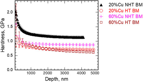
FIGURE 8. Hardness versus depth for 20% and 60% Cu donor stir NHT and HT BM samples.
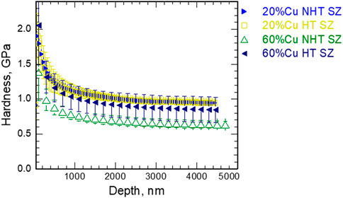
FIGURE 9. Hardness versus depth for 20% and 60% Cu donor stir NHT and HT SZ samples.
A hardness across the weld plot is shown in Figure 10. The data which are obtained using high-load nanoindentation tip for the as welded 1,400 rpm- 1 mm/s sample are shown in this plot. The hardness covers the region from the RS to the AS. The RS of the weld closer to the tool pin depicted lower hardness compared to the AS. Successive plastic deformation caused by the tool pin created plastic strains that cause the hardness to drop in the RS. The lowest hardness occurred in the HAZ with hardness values as low as 0.45 GPa as compared to the hardness values of 0.67 GPa that occurred at the BM.
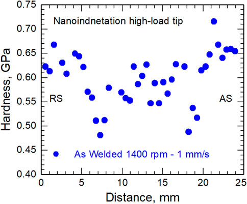
FIGURE 10. Hardness profile of the high load nanoindentation tip.
The microstructure of the 20% and 60% Cu donor stir HT samples for the BM and the SZ are shown in Figure 11. The grains are larger for the BM when compared to the SZ grains due to recrystallization that developed at the SZ. The hardness at the SZ for the 20% Cu donor stir HT BM sample is 0.69 GPa as compared to the hardness of 0.93 GPa for the SZ. The 60% Cu donor stir HT BM depicted similar results of a hardness of 0.61 GPa compared to a hardness of 0.82 GPa for the SZ. This also correlates well with the Hall-Petch effect as the hardness increases with the decrease of the grain size.
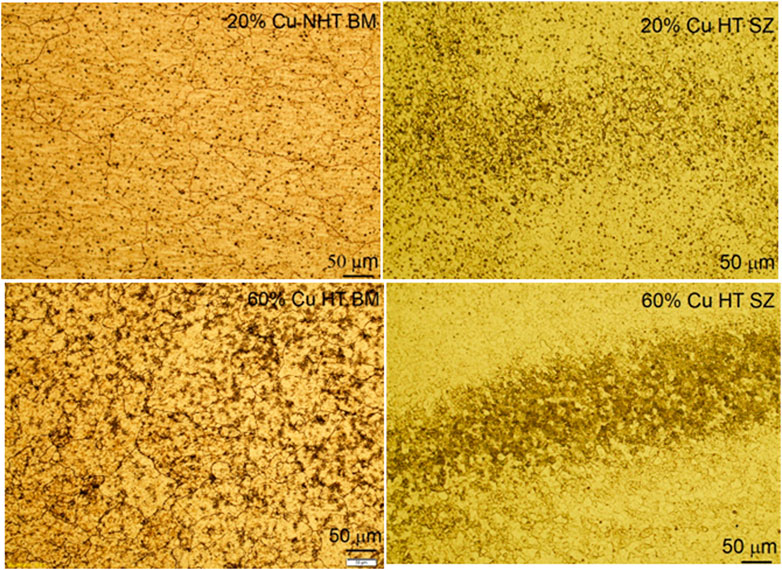
FIGURE 11. Microstructure of the 20% and 60% Cu HT samples BM (top left) and SZ (top right).
The elastic modulus of the FSW 20%, 60% Cu, NHT and HT samples is shown in Figure 12. The elastic modulus is calculated from the contact area and the measured unloading stiffness as given by the relation
where
where
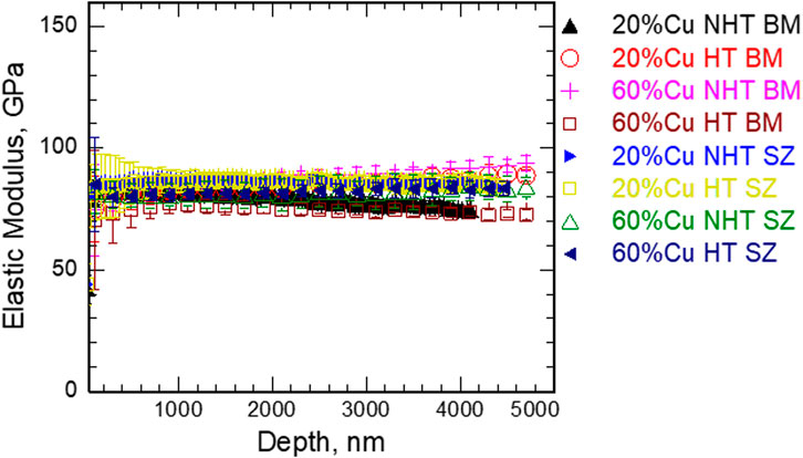
FIGURE 12. Elastic modulus versus depth of indentation.
The elastic moduli vary between
4 Conclusion
The nanomechanical properties were measured using nanoindentation. The continuous stiffness method (CSM) in-depth control was used for the 20% and 60% Cu donor stir NHT and HT samples. The hardness and elastic modulus were measured for two regions, the base metal (BM) and the stir zone (SZ). The hardness of the 20% and 60% Cu HT samples at the SZ was higher than the hardness of the same samples at the BM. This decrease in hardness was due to the recrystallization at the SZ zone. It is also concluded that the hardness of the weld at the SZ is similar to the hardness of the Al6061-T6 plate. This suggests that the Cu donor stir material did not impact the hardness properties of the Al6061-T6 plate due to the purging of the Cu donor stir material during the welding process, an important result of the concept of the donor material. The SEM-EDS of the samples also verified this. The XRD results of the 20%, 60% Cu NHT, and HT donor stir samples depicted orientations similar to the orientation of the Al6061-T6 original material, as expected. However, these orientations are different from the orientation of the Cu plate, a significant result that indicates the Cu donor stir material is depleted at the end of the welding process resulting in a homogenous weld. The hardness and modulus results of all the samples depicted the hardness and modulus of the Al6061-T6 plate, which is also expected. The elastic moduli of the Cu donor stir welded samples were found to be different from the modulus of the Cu 110 material and similar to the elastic modulus of aluminum alloys which is also an important outcome.
Data availability statement
The raw data supporting the conclusion of this article will be made available by the authors, without undue reservation.
Author contributions
MO SEM-EDS, AA-A XRD, YM nanoindentation, SB FSW samples fabrication, ZW secured the funding for this project, AE conception and design of the study.
Funding
NASA (award number: 80NSSC20M0015).
Acknowledgments
The authors would like to acknowledge support from NASA (award number: 80NSSC20M0015). Any opinions, findings, and conclusions or recommendations expressed in this material are those of the author(s) and do not necessarily reflect the views of the NASA.
Conflict of interest
The authors declare that the research was conducted in the absence of any commercial or financial relationships that could be construed as a potential conflict of interest.
Publisher’s note
All claims expressed in this article are solely those of the authors and do not necessarily represent those of their affiliated organizations, or those of the publisher, the editors and the reviewers. Any product that may be evaluated in this article, or claim that may be made by its manufacturer, is not guaranteed or endorsed by the publisher.
References
Adesina, A. Y., Al-Badour, F. A., and Gasem, Z. M. (2018). Wear resistance performance of AlCrN and TiAlN coated H13 tools during friction stir welding of A2124/SiC composite. J. Manuf. Process 33, 111–125. doi:10.1016/j.jmapro.2018.04.019
Ahmed, M. M. Z., Jouini, N., Alzahrani, B., Seleman, M. M. E.-S., and Jhaheen, M. (2021). Dissimilar Friction Stir Welding of AA2024 and AISI 1018: Microstructure and Mechanical Properties, 11. doi:10.3390/met11020330Met. (Basel)
Bhukya, S. N., Wu, Z., Maniscalco, J., and Elmustafa, A. (2022). Effect of copper donor material-assisted friction stir welding of AA6061-T6 alloy on downward force, microstructure, and mechanical properties. Int. J. Adv. Manuf. Technol. 119, 2847–2862. doi:10.1007/s00170-021-08390-8
Bhukya, S., Wu, Z., and Elmustafa, A.(2023). “Effect of post weld heat treatment on donor material assisted friction stir welding of AA6061-T6 alloy on microstructure and mechanical properties,” in Flexible Automation and Intelligent Manufacturing: The Human-Data-Technology Nexus. Editors K. Y. Kim, L. Monplaisir, and J. Rickli FAIM 2022. Lecture Notes in Mechanical Engineering (Springer, Cham). doi:10.1007/978-3-031-17629-6_10
Bousquet, E., Poulon-Quintin, A., Puiggali, M., Devos, O., and Touzet, M. (2011). Relationship between microstructure, microhardness, and corrosion sensitivity of an AA 2024-T3 friction stir welded joint. Corros. Sci. 53, 3026–3034. doi:10.1016/j.corsci.2011.05.049
Cabibbo, M., Forcellese, A., Santecchia, E., Paoletti, C., Spigarelli, S., and Simoncini, M. (2020). New approaches to friction stir welding of aluminum light-alloys. Met. (Basel) 10, 233. doi:10.3390/met10020233
Chen, G., Zhang, S., Zhu, Y., Yang, C., and Shi, Q. (2020). Thermo-mechanical analysis of friction stir welding: A review on recent advances. Acta Metall. Sin. 33, 3–12. doi:10.1007/s40195-019-00942-y
Elmustafa, A. A., and Stone, D. S. (2002). Indentation size effect in polycrystalline F.C.C. metals. Acta Mater 50, 3641–3650. doi:10.1016/S1359-6454(02)00175-1
Elmustafa, A. A., and Stone, D. S. (2003). Nanoindentation and the indentation size effect: Kinetics of deformation and strain gradient plasticity. J. Mech. Phys. Solids 51, 357–381. doi:10.1016/S0022-5096(02)00033-9
Gao, S., Wu, C. S., and Padhy, G. K. (2019). Effect of leading ultrasonic vibrations on the welding forces of friction stir lap welding. Int. J. Adv. Manuf. Technol. 104, 3181–3189. doi:10.1007/s00170-019-04264-2
Gražulis, S., Chateigner, D., Downs, R. T., Yokochi, A. F. T., Quirós, M., Lutterotti, L., et al. (2009). Crystallography open database – An open-access collection of crystal structures. J. Appl. Crystallogr. 42, 726–729. doi:10.1107/S0021889809016690
Gražulis, S., Merkys, A., Vaitkus, A., and Okulič-Kazarinas, M. (2015). Computing stoichiometric molecular composition from crystal structures. J. Appl. Crystallogr. 48, 85–91. doi:10.1107/S1600576714025904
Haghshena, M., and Gerlich, A. P. (2018). Joining of automotive sheet materials by friction-based welding methods: A review, engineering science and technology. Int. J. 21, 130–148.
Haghshenas, M., and Gerlich, A. P. (2018). Joining of automotive sheet materials by friction-based welding methods: A review. Int. J. 21, 130–148. doi:10.1016/J.JESTCH.2018.02.008
Hailat, M. M., Mian, A., Chaudhury, Z. A., Newaz, G., Patwa, R., and Herfurth, H. J. (2012). Laser micro-welding of aluminum and copper with and without tin foil alloy. Microsyst. Technol. 18, 103–112. doi:10.1007/s00542-011-1378-8
Hasieber, M., Wenz, F., Gratzel, M., Lenard, J. A., Matthes, S., and Bergmann, J. P. (2022). A systematic analysis of maximum tolerable tool wear in friction stir welding. Berlin, Germany: Weld World. doi:10.1007/s40194-022-01407-0
Hossfeld, M. (2022). Modeling friction stir welding: On prediction and numerical tool development. Metal 12, 1432. 1–15. doi:10.3390/met12091432
Majeed, T., Mehta, Y., and Siddiquee, A. N. (2021). Analysis of tool wear and deformation in friction stir welding of unequal thickness dissimilar Al alloys. Proc. Institution Mech. Eng. Part L J. Mater. Des. Appl. 235 (3), 501–512. doi:10.1177/1464420720971769
Mandal, S., Rice, J., Hou, G., Williamson, K. M., and Elmustafa, A. A. (2013). Modeling and simulation of a donor material concept to reduce tool wear in friction stir welding of high-strength materials. J. Mater Eng. Perform. 22, 1558–1564. doi:10.1007/s11665-012-0452-4
Maniscalco, J., Elmustafa, A. A., Bhukya, S., and Wu, Z. (2022). Numerical simulation of the donor assisted stir material for friction stir welding of aluminum alloys and carbon steel. Int. J. Material Form. Rev. 13, 164. doi:10.3390/met13010164)
Merkys, A., Vaitkus, A., Butkus, J., Okulic-Kazarinas, M., Kairys, V., and Grazulis, S. (2016). COD::CIF::Parser: An error-correcting CIF parser for the perl language. J. Appl. Crystallogr. 49, 292–301. doi:10.1107/s1600576715022396
Oliver, W. C., and Pharr, G. M. (2004). Measurement of hardness and elastic modulus by instrumented indentation: Advances in understanding and refinements to methodology. J. Mater Res. 19, 3–20. doi:10.1557/jmr.2004.19.1.3
Quirós, M., Gražulis, S., Girdzijauskaitė, S., Merkys, A., and Vaitkus, A. (2018). Using SMILES strings for the description of chemical connectivity in the Crystallography Open Database. J. Cheminform 10, 23. doi:10.1186/s13321-018-0279-6
Rice, J. M., Mandal, S., and Elmustafa, A. A. (2014). Microstructural investigation of donor material experiments in friction stir welding. Int. J. Material Form. 7, 127–137. doi:10.1007/s12289-012-1110-y
Sahlot, P., Jha, K., Dey, G. K., and Arora, A. (2018). Wear-induced changes in FSW tool pin profile: Effect of process parameters. Metall. Mater Trans. A 49 (6), 2139–2150. doi:10.1007/s11661-018-4580-9
Shah, R. S., and Warke, D. A. (2017). Review paper on fatigue strength and tool life for friction stir welding. Int. J. Adv. Res. Innovative Ideas Educ. 3 (6), 1811–1815.
Shi, L., Wu, C. S., and Liu, X. C. (2015). Modeling the effects of ultrasonic vibration on friction stir welding. J. Mater Process Technol. 222, 91–102. doi:10.1016/J.JMATPROTEC.2015.03.002
Stegall, D. E., and Elmustafa, A. A. (2018). The contribution of dislocation density and velocity to the strain rate and size effect using transient indentation methods and activation volume analysis. Metallurgical Mater. Trans. A 49, 4649–4658. doi:10.1007/s11661-018-4817-7
Stegall, D. E., Mamun, Md.A., Crawford, B., and Elmustafa, A. (2012). Indentation size effect in FCC metals: An examination of experimental techniques and the bilinear behavior. J. Mater Res. 27, 1543–1552. doi:10.1557/jmr.2012.91
Wang, X., Gao, Y., McDonnell, M., and Feng, Z. (2020). On the solid-state-bonding mechanism in friction stir welding. Extreme Mech. Lett. 37, 100727. doi:10.1016/J.EML.2020.100727
Keywords: nanoindentation, friction stir welding, donor stir material, XRD, SEM-EDS
Citation: Ojha M, Al-Allaq AH, Mohammed YS, Bhukya SN, Wu Z and Elmustafa AA (2023) Elastic properties of the non-mixing copper donor assisted material in friction stir welding of aluminum alloys using nanoindentation. Front. Met. Alloy 2:1129126. doi: 10.3389/ftmal.2023.1129126
Received: 21 December 2022; Accepted: 27 February 2023;
Published: 13 March 2023.
Edited by:
Anil K. Battu, Pacific Northwest National Laboratory (DOE), United StatesReviewed by:
Elisa Fracchia, Polytechnic University of Turin, ItalyKaushal Kishore, Tata Steel, India
Copyright © 2023 Ojha, Al-Allaq, Mohammed, Bhukya, Wu and Elmustafa. This is an open-access article distributed under the terms of the Creative Commons Attribution License (CC BY). The use, distribution or reproduction in other forums is permitted, provided the original author(s) and the copyright owner(s) are credited and that the original publication in this journal is cited, in accordance with accepted academic practice. No use, distribution or reproduction is permitted which does not comply with these terms.
*Correspondence: A. A. Elmustafa, YWVsbXVzdGFAb2R1LmVkdQ==