 William Reed Kendrick*
 Benoit Forget
- Computational Reactor Physics Group, Department of Nuclear Science and Engineering, Massachusetts Institute of Technology, Cambridge, MA, United States
Multiphysics analysis has become a common technique for nuclear reactor design validation, with neutronic-thermal analysis being the typical choice for understanding reactor dynamics. The concept of adding mechanical simulation such as thermal expansion to this coupling is still relatively new, however, and presents many computational challenges. While large reactors see relatively little neutronic impact from thermal expansion and may not warrant the challenge of undertaking this level of coupling, recent studies of microreactor geometries show that smaller reactors see larger impacts from thermal expansion. This work performs coupled neutronic-thermal-mechanical simulation of the Kilowatt Reactor Using Stirling TechnologY (KRUSTY) using OpenMC and Multiphysics Object-Oriented Simulation Environment in order to analyze the neutronic and thermal impact of including thermal expansion at steady state. The results show that while thermal expansion has a significant effect on global neutronic tallies, it has relatively minor impact on spatial heating rates or temperatures in the system. This remains true even when simulating a multiple heat pipe failure scenario to introduce thermal asymmetry.
1 Introduction
Nuclear reactors are environments of high temperature profiles and large neutron fluxes. These two characteristics are tied together through complicated feedback mechanisms. Neutron flux dictates fission rate, fission rate dictates heating, heating dictates temperature, and temperatures can cause significant changes in material microscopic cross-section, which finally impacts neutron flux. This feedback loop is one of the strongest that exists in nuclear reactors, providing an important control mechanism (Oka, 2013). This is why coupling of neutronic-thermal simulations is a widely seen reactor design methodology, particularly with the rise of high performance computing and parallelizable codes. These studies can be found for nearly every reactor type that has been conceptualized.
As computing architecture and simulation codes have advanced, there has been rising interest in adding an additional level of physics to the neutronic-thermal coupling. One notable addition would be including solid-mechanical simulation to account for geometric deformation of different parts of the reactor environment. During real operation of a nuclear reactor, the high temperature of the core causes materials to expand, neutron irradiation can cause swelling or contraction, and fuel materials will experience swelling due to fission gas and lattice damage. These geometric changes impact the spatial neutron flux in the core, which in turn becomes another feedback loop for the reactor.
For most large-scale cores, like classic gigawatt-scale reactors, thermal expansion has a relatively limited effect on neutron flux due to the scale of the system (Edenius, 1976). For smaller reactor geometries, such as microreactors, this is not the case. The NASA-produced Kilowatt Reactor Using Stirling TechnologY (KRUSTY) (Gibson et al., 2018) is a good example of this, with related works reporting that roughly 85% of net reactor feedback is caused by thermal expansion of the fuel (Poston et al., 2020a).
This reactivity impact from thermal expansion provides an impetus for this work to implement and analyze a neutronic-thermal-mechanical simulation of the KRUSTY microreactor environment, with an additional study on the impact of heat pipe failure. Neutronics are solved in OpenMC, and thermal-mechanical modeling is performed with INL’s Multiphysics Object-Oriented Simulation Environment (MOOSE). Of particular attention in this study is identifying how thermal expansion of the reactor features change spatial heating rates and material reaction rates, as well as the following temperature distributions in the core. Importantly, the results of this study will help suggest whether this sort of neutronic-thermal-mechanical coupled simulation is a necessary study for similarly small reactor types in the future. For example, if the thermal expansion causes significant enough changes in temperature distribution of the core, it may mean that a purely neutronic-thermal simulation is insufficient to predict core behavior. A test case on heat pipe failure is included in order to analyze how the results change when the temperature profile is asymmetric in the core due to failed heat pipes.
2 Background
Described in the following section are some of the general concepts and features that are necessary to understand the work of this study. These topics include a brief explanation of the KRUSTY reactor design with emphasis on why it has been chosen as the reactor of choice for this study, followed by an overview of the mechanics of thermal expansion and other geometric deformation sources commonly seen in nuclear reactors. This is followed by a description of Direct Accelerated Geometry Monte Carlo (DAGMC), a technique that is used extensively in the coupling method described in Section 3.1. Finally, because neutronic-thermal-mechanical coupled simulation is beginning to become more prevalent, some contemporary approaches to solving this sort of problem are discussed to contrast the ways in which the approach described by this study differs.
The KRUSTY reactor, as suggested by its full name, is a relatively simple and lightweight prototype reactor design intended to provide propulsion in outer space via heat exchange with Stirling engines (Gibson et al., 2018). The design went through extensive testing in early 2018, and several papers exist documenting the testing results (Gibson et al. (2018); David et al., 2020; Poston et al. (2020b); Poston et al. (2020a); Sanchez et al. (2020)). The geometry studied for this work does not include the entire reactor-engine system, but only the core and surrounding shield and reflector structures.
A depiction of the representative core simulated in this work can be seen in Figure 1, colored by material. The core features a central, annular fuel block of U-7.65Mo, highly enriched to approximately 93%
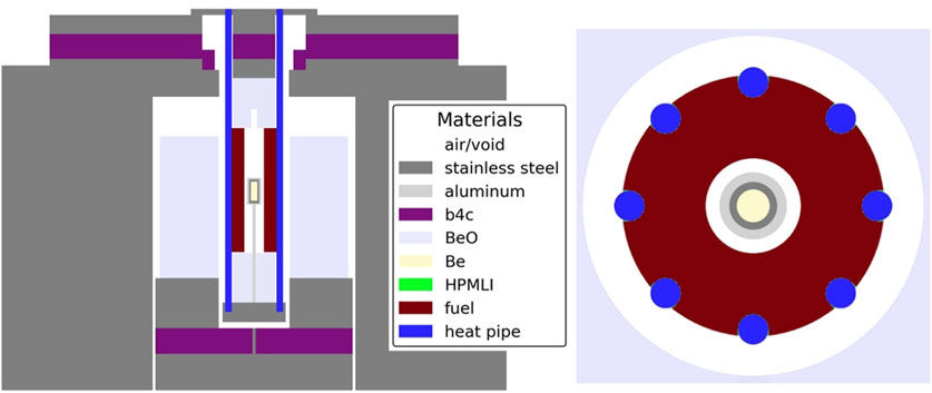
Figure 1. Geometry of the KRUSTY reactor showing materials in an YZ (left) and XY (right) slice. Fuel is UMo, central beryllium acts as a neutron multiplier. HPMLI is a multilayer insulation that coats the inward-facing surface of the heat pipes.
The mesh geometry representative of the KRUSTY reactor used in this work comes from the Virtual Test Bed Repository hosted by Idaho National Lab (Giudicelli et al., 2023), and is a result of the work of Dr. Kun Mo and Dr. Soon Kyu Lee of Argonne National Lab. This geometry serves as a relatively accurate model of the true KRUSTY reactor.
What should stand out from the previous descriptions of the core is that this is a fast spectrum system. There is no moderator, and it relies on reflectors to keep the reactor critical. From a neutronics perspective, this means temperature variation of the medium has less of an impact on neutron flux because Doppler broadening is most impactful for resonance absorption during the slowing-down process (Springer et al., 1969). Fast spectrum systems, however, are more reactive to neutron leakage because fast neutrons have a greater probability of escaping the reactor—hence the need for thick reflectors surrounding the core.
This leakage-constrained behavior is likely one of the reasons why thermal expansion is reported by Poston et al. (2020a) as having the dominant impact on reactivity. Previous work by the authors that focused on thermal expansion along with neutronic-thermal simulation of small modular reactors found that the main impact of thermal expansion was on neutron leakage (Kendrick, 2024). This suggests that KRUSTY is a very good test case for analyzing the impact of thermal expansion on neutronic-thermal simulation results.
As a sanity-verification method, the fact that volumetric expansion causes increased neutron leakage can be proven with a simple toy problem. Imagine a regular cube with a neutron born at the center of the cube. The task is to determine how probability of leakage of that neutron changes after volumetric expansion. If there is uniform expansion of 10%, in order to conserve mass the density must decrease by the reciprocal, 0.909. Additionally, the distance the neutron must travel to any surface on the cube is directly related to the length of the sides of the cube, which have increased by a factor of
where
2.1 Thermal expansion and geometric deformation
Thermal expansion is a well defined topic, being a phenomenon that humans have recorded for hundreds of years and have experienced for far more. Thermal expansion occurs on the molecular level as increased temperatures are a manifestation of an increase in kinetic energy. This increased kinetic energy results in more frequent neighboring body interactions, which translate into vibrations. These vibrations lead to an increase in distance from the surrounding atoms because of the anharmonicity between the attractive and repulsive forces that govern the lattice. Whether a material will expand or contract with increasing temperature depends on the balance of these forces that is specific to the material and state of the material in question (Bower, 2009).
The core of a nuclear reactor is an environment with extreme temperatures and sees significant thermal expansion of its materials, isotropically and anisotropically. Quantifying the per-degree effect of temperature change on neutron balance via a reactivity coefficient has been a longstanding practice for reactor engineers in order to understand transient reactor behavior and inform point kinetic models. This quantity rarely includes the thermal expansion effect for the solid materials in the core, however. This is because in traditional light-water reactors at steady state, the effect of thermal expansion on eigenvalue (the ratio of neutrons produced per neutron destroyed) is fairly minor, with the largest effect being a change in the leakage of fast spectrum neutrons (Edenius, 1976).
While this does have more of an impact in KRUSTY-sized reactors, as previously noted, thermal expansion is still very much a topic of analysis for reactor engineers regardless of reactor design. This is because of the concern of material failure due to mechanical stress, either within a material itself or at a contact point with another material.
For the purposes of this work, neither anisotropic expansion (e.g., mono-crystal behavior) nor potential mechanical failure are taken into account, although anisotropy may be possible to model by defining material lattice planes. Instead, the focus of this work is on the impact of non-uniform, isotropic-in-cell, elastic thermal expansion on core neutronic behavior and simulating the thermal-neutronic feedback loop.
Although thermal expansion is the only deformation mechanism included in this study, it is not the only method of geometric deformation that nuclear reactors experience during operation. A notable method of geometric deformation is fission-induced swelling of the fuel material. This process occurs as fission products collide and decelerate in the fuel material, creating vacancies and displacements as well as depositing themselves throughout. These fission products are a mix of solid and gaseous states, and result in a swelling effect for the fuel (Massih, 1988).
The gaseous fission products are especially accelerative for the swelling process, as the fission products will migrate to grain boundaries and cavities. These gasses then experience larger thermal expansion than their solid-state counterparts, increasing expansion and encouraging material fracture (Lietzke, 1970). Because of the inherent risk of highly radioactive, gaseous fission products escaping the fuel, the U.S. Nuclear Regulator Commission includes fission gas release and swelling modeling as a part of the fuel qualification process (Drezewiecki et al., 2021). This has led to fuel swelling being a well-documented and modeled phenomenon (Andrews, 2012).
While this study neglects these non-temperature-dependent methods of geometric deformation that do regularly occur in reactor cores, the sole study of thermal expansion and its effects is useful as it provides a baseline for future deformation cases. Being able to define that
2.2 DAGMC
The largest hurdle involved in neutronic-thermal coupling is reconciling the difference in native environment in which each type of simulation operates. Thermal coupling is typically performed on an unstructured mesh geometry via the finite element method where calculations are performed iteratively over quadrature points located within mesh elements. Neutronic calculations, when simulated via Monte Carlo particle transport, are typically performed on Constructive Solid Geometry (CSG) geometries where surfaces are defined with analytical geometric expressions and cell spatial regions are defined by Boolean half-spaces. In order to couple the two together, something must be altered. This work utilizes Direct Accelerated Geometry for Monte Carlo (DAGMC) to alter the geometry that particle transport occurs on.
DAGMC is a software library developed for neutronic modeling of fusion reactor geometries, allowing the user to translate Computer-Aided Design (CAD) geometries into Monte Carlo-solvable inputs (Tautges et al., 2009). The software has since seen use in both fission and fusion applications, and features an ability to couple with the Sandia National Laboratories-based Coreform Cubit software to automate CAD-to-CSG transfers (Blacker et al., 1994). Coreform Cubit has a feature capable of exporting DAGMC geometries directly from coarse meshes, of which this study takes advantage (Coreform, 2024). This facet geometry replaces the geometry block of information traditionally used for OpenMC problem description. In order to do so, temperatures and material assignments are made on the mesh and are stored within the facet geometry.
The DAGMC geometry consists of planar body representations, on which OpenMC is well-equipped to perform transport calculations. DAGMC’s integration with OpenMC is well documented and there exists a robust literature documenting its use (Davis et al., 2020). While the planar bodies work well for representing tessellated surfaces, this does still mean that surfaces that were originally second-order or higher, such as the outer surface of a cylinder, will incur severe computational penalties.
2.3 Contemporary approaches to multiphysics simulation
As previously mentioned in the beginning of this section, the concept of coupling thermal expansion to neutronic-thermal simulation is not a novel one; in fact, the last 5 years have seen a number of papers published on this topic featuring a wide range of coupling methods and reactor geometries (Hu et al., 2019; Ma et al., 2021; Yan et al., 2020; Chen C. et al., 2023; Pope and Lum, 2020; Xiao et al., 2022; Jeong et al., 2023; Walker et al., 2022; Aldebie et al., 2024; Sterbentz et al., 2017; Chen H. et al., 2023).
The majority of these works have been related to reactors larger than KRUSTY. The work in Stauff et al. (2021) details the use of MOOSE coupled with Griffin (Lee et al., 2021) to simulate thermal stress and strain on a hypothetical heat pipe small modular reactor. Stauff notes a maximum axial displacement of 1.5 cm and a maximum stress located between neighboring heat pipes, but does not note any impact on neutronic or thermal behavior due to thermal expansion. The author’s work on the same geometry, utilizing the methods described in this work, saw that this was a fair conclusion, as expansion was only impactful on leakage (Kendrick, 2024). In a study on a fast-spectrum reactor, Walker reported an impact of roughly 7 pcm per Kelvin due to combined axial expansion of fuel and radial expansion of reflector and cladding (Walker et al., 2022).
This sort of analysis for microreactors is slightly rarer, but there does exist a study on KRUSTY produced by Chen (Chen H. et al., 2023). Chen utilizes OpenMC to solve the initial power distribution, then uses MOOSE to solve the thermal profile of the core, along with a tensor mechanics solve to simulate thermal expansion. This work does not feed the deformed geometry back into OpenMC, however, so thermal expansion’s impact on neutronic and therefore thermal behavior is not noted. Chen’s work is focused on transient behavior analysis by tying a point kinetics model to adjust power amplitude while maintaining the original spatial power distribution. Poston’s work (Poston et al., 2020a) is the closest to reporting an effect on reactivity due to thermal expansion, as the author has mentioned earlier. The details of the coupling scheme are not clear, however, except for MCNP being the particle transport code used and FRINK being used for the rest of the physics.
To generalize the works of this nature thus far, it is useful to categorize them by the methodology used for neutronics. Often seen, like in the work of Stauff et al. (2021), is solving neutron/photon behavior via deterministic methods like diffusion. This is particularly appealing because this sort of transport solve functions well in an unstructured mesh environment. A good example of the utility of this is the Griffin code that can operate in the MOOSE framework, allowing for rapid iteration of a coupled solution. This ability becomes particularly advantageous when the mesh deforms during the solve. The downside to this sort of deterministic calculation is well known; deterministic methods require competent cross-section generation for the geometry in order to preserve reaction rates. This is sometimes done via a Monte Carlo simulation (Redmond, 1997) which cuts into the potential computation time gains from using deterministic methods in the first place, and geometric deformations that strongly affect neutron flux would potentially require updated cross-sections mid-solve. Couple this with some of the inherent inaccuracies dependent on the deterministic method used, and there may be a question of neutronic uncertainty that is hard to quantify.
The alternative to this is to rely on Monte Carlo simulation for neutronics. Monte Carlo is still considered too computationally expensive for Light Water Reactors (LWRs) full-core calculations, even with modern computing advances. However, a full-core calculation of a microreactor like KRUSTY is far different, given the dimensions of the KRUSTY reactor are smaller than the dimensions of a single AP-1000 assembly. The challenge is reconciling how to transfer information typically generated in a Constructive Solid Geometry environment to the thermal solve in an unstructured mesh environment. This work’s approach is to use DAGMC to skin CAD geometries into planar bodies and solve particle transport in this CAD-derived environment, but this method has nuances as mentioned in Sections 2.2 and 3.3. A simpler alternative is to build a 1-to-1 CSG representation of the mesh geometry, but that approach fails when non-uniform deformation occurs.
It is clear that neutronic-thermal-mechanical studies are still in their infancy. As will be obvious in the following section detailing the coupling methodology, adding solid mechanics introduces significant complexity that often requires reducing the accuracy in other areas of the solve. It is this author’s hope that this work serves to be another stepping stone in the pathway towards a well-defined process for tackling this sort of simulation in the future.
3 Methods
This section details the methods utilized to perform neutronic-thermal-mechanical simulation on the KRUSTY reactor geometry. First, this section provides a short summary of the two main codes used in this work, OpenMC and MOOSE. This is followed by three subsections, beginning with a detailed explanation of the coupling scheme used to connect the neutronic and thermal-mechanical solves. The final two subsections respectively detail some of the complexities and assumptions used in the MOOSE and OpenMC solves.
MOOSE is a finite element physics framework initially developed at Idaho National Laboratory (Giudicelli et al., 2024). It features extremely parallelizable code for high efficiency on computing clusters, along with well documented and user-friendly methods for implementing one’s own physics kernels. MOOSE is used for all thermal conduction and thermo-mechanics simulation in this work, relying on modules that are readily available as part of the open-source MOOSE environment (Shemon et al., 2023; Adhikary et al., 2016). All simulations using MOOSE utilize the finite element method with Lagrangian variable representation. The Newton scheme of non-linear solving was applied, with the default MOOSE Jacobian preconditioning.
OpenMC is an open-source Monte Carlo neutron and photon transport simulation code initially developed by Massachusetts Institute of Technology (Romano et al., 2015). OpenMC can perform steady state eigenvalue calculations on complicated geometries in both continuous energy and multigroup with tallying capabilities for heat deposition (Romano, 2020). OpenMC was developed with a strong emphasis on parallelism, taking advantage of the fact that the Monte Carlo method has some inherent advantages for parallel computing (Rosenthal, 2000). This parallelization allows the software to scale well with larger system architectures like supercomputers, which this work utilizes.
3.1 Coupling scheme
A flowchart diagram depicting the coupling scheme is included in Figure 2, showing the flow from mesh generation to final results compilation. The initial work done before the main iteration is primarily focused on mesh generation and parsing. Mesh generation is performed using the MOOSE Reactor module (Shemon et al., 2023). This module allows regularized mesh generation for reactor core geometries, in particular geometries with repeated features such as Cartesian and hexagonal lattices.
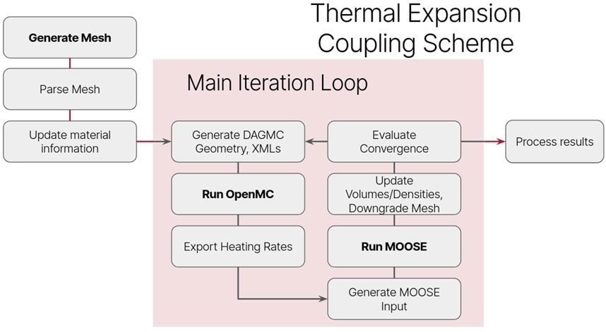
Figure 2. General flowchart for the full coupled simulation.
The process of parsing the mesh occurs following this generation. Because the OpenMC-DAGMC geometry is derived from the mesh, all cell references now must be references to mesh volume IDs. Building the arrays of IDs that establish what materials are found in each volume as well as calculating and tabulating volumetric data for each mesh volume is handled during the parsing step. This is accomplished via Coreform Cubit’s Python API, without which a manual inspection of the mesh would be required. A dictionary cataloging each core material and its properties, along with mesh volume IDs that feature that material, is instantiated and populated at this time as well. The volume of each cell is recorded in order to modify material densities post-expansion to conserve mass in the system.
3.2 MOOSE and mesh deformation
One of MOOSE’s strongest selling points for this sort of study is its library of existing modules that cover a wide range of physics kernels. Included amongst these is the Solid Mechanics module, which contains the specific material and physics blocks used to simulate thermal expansion in the KRUSTY reactor. An operations outline of the MOOSE input can be seen in Figure 3. This figure does not include post-processors and the material blocks used to apply thermal and mechanical material properties. An explanation for each subset of the input, corresponding to the connected letters seen in Figure 3, is as follows:
1. Kernel activating heat conduction and the input volumetric heating rates for every mesh volume. Each volume has the OpenMC-generated volumetric heating rate applied via the HeatSource block.
2. Dirichlet boundary to represent the heat pipes for main heat removal. As a simple representation of the heat removal functions of real-life heat pipes, DirichletBCs were applied to all heat pipe surfaces with a value of 1050K to mimic the results from Poston et al. (2020a).
3. Outer, top, and bottom boundary heat removal. This is an arbitrary natural convection heat loss representation, in order to mimic natural convection with ambient air. This inclusion allows for a more realistic temperature profile for the outer air materials, given their otherwise isolated condition.
4. Anchoring Boundary Conditions. Because thermal expansion is isotropic in-cell, displacement at certain boundaries need to be anchored with a DirichletBC in order to avoid mesh overlap in particular. Note that a truly accurate simulation would not need these boundaries, but because of the removal of air in particular (for reasons stated later in this section), MOOSE does not recognize overlapping meshes.
5. Instantiation and solving of thermal expansion-based eigenstrains, strains, and stress. The first block, SolidMechanics/QuasiStatic is a MOOSE Action object that instantiates all the needed data for a Solid Mechanics problem. ComputeThermalExpansionEigenstrain calculates the eigenstrain tensor resulting from isotropic thermal expansion, given the temperature at the quadrature point versus the input stress-free temperature. These eigenstrains lead to stresses calculated by ComputeFiniteStrainElasticStress given the material properties computed by a ComputeIsotropicElasticityTensor.
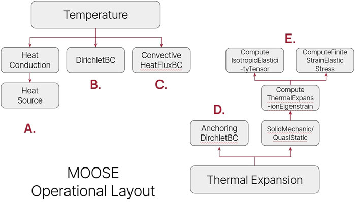
Figure 3. MOOSE operations during thermal expansion. Processes correspond to numbers (e.g. A = 1, B = 2) that are further explained in Section 3.2.
The result of these inputs is a solution that thermally solves temperature in the system and displaces mesh node points based on thermal expansion eigenstrain tensors. The output mesh is now deformed, and can be converted via DAGMC for an OpenMC particle transport solve.
While the process seen in Figure 2 does not involve any custom code, it does introduce two significant complications needing to be mentioned. Firstly, the use of Dirichlet boundary conditions for the heat pipes results in a loss of heat in the system. This non-conservation arises because the MOOSE solve uses the finite element method, which is globally conservative but not necessarily locally conservative (LeVeque, 2002). The finite element equations at the boundary solve one value, but the Dirichlet boundary is strongly enforced and overwrites the calculated values, thus the solution may not satisfy conservation (Hubbard et al., 2009; Hughes et al., 2000). Using higher order meshes reduces this error, and using a Neumann boundary condition removes the error. The results of this study do use Dirichlet boundaries so this non-conservation exists, and may slightly affect reported temperature profiles.
The second complication has to do with mesh element inversion. This occurs when the displacement of one node moves that node to a new position such that when the volume of the element is calculated, it returns a negative value. This causes the Jacobian of that mesh element to turn negative as well, and causes a simulation failure. Areas where this tends to occur are places with coarse meshes, thin layers, and high displacement regions. In order to avoid these sorts of issues, the air mesh blocks in the reactor geometry and two thin layers of aluminum and steel (representing the ring clamp and vacuum can) were removed. Neutronically, these material removals are inconsequential. Air is not dense enough to significantly impact neutron transport, and the aluminum and steel layers are very thin (0.318 cm thickness for the ring clamp, 0.305 cm thickness for the vacuum can).
These features are thermally impactful. In reality, the vacuum can has multi-layer insulation on its fuel-facing side, keeping the air and emissivity from transferring much heat radially. Our removal of the can and air material nearly perfectly insulates the radial reflector, in a similar manner. Comparing the reported radial reflector operating temperatures Poston et al. (2020a) with the pre-expansion temperature profile results in Figure 7, these temperatures are very close, 343 K versus 330 K, respectively.
The removal of air does, however, affect the temperature of the axial reflectors, as without it there is no method of heat removal besides the heat pipes at 1050 K. This causes temperatures of 1050 K and 700 K seen in Figure 7 versus the Poston reported 473 K. The higher temperature in this paper’s simulation will result in an overestimation of expansion for the axial reflectors. That being said, in the volume expansion results seen in Figure 8, the axial reflectors still experience much less expansion versus in the UMo fuel. Based on the work of Jamison et al. (2020) used for this simulation, at 1050 K, BeO would have a thermal expansion coefficient of 1.04E-5, while UMo would have a thermal expansion coefficient of 2.06E-4.
3.3 OpenMC and heat pipe representation
As noted in the previous subsection, heat pipe representation during the thermal/mechanical solve in MOOSE is essentially a surface representation. The interior of the heat pipe is not utilized in the computational model. In fact, the inclusion of a material inside the heat pipe often will negatively impact the heat pipe representation, as it influences the heat flux recorded at the heat pipe boundary. One way of handling this is to remove the mesh blocks that describe the heat pipes, as only the surface of the blocks are needed (Kendrick, 2024). Although this work does not use a true heat pipe model, the same process of removing heat pipe mesh elements has been done.
This presents a problem, however. For a coupling method that performs neutronics on the DAGMC facet geometry based on the mesh output, this would mean removing the heat pipes from the neutronic solve as well. Unlike the previously mentioned removal of air from the mesh geometry, heat pipes are neutronically an important feature due to the stainless steel casing and sodium fluid. Neglecting this would make the neutronic results significantly less realistic.
The solution the author found was to insert heat pipes into the geometry on the OpenMC side by importing the DAGMC geometry not as the root universe, but instead as a cell. This is a somewhat complicated process of geometry definition, where the region that the DAGMC cell inhabits is defined by a set of core bounding surfaces and by excluding every heat pipe region. This requires that the boundaries of the heat pipes be excluded from any mesh deformation such that the OpenMC heat pipes do not accidently overwrite any fuel material. This does cause a slight “flowering” radial expansion shape for the fuel, seen in Figure 8, rather than pushing the heat pipes outwards along with the fuel, which would be seen in reality.
Another side effect of this arises from the fact that the cylindrical regions for the heat pipes do not exactly fit the empty regions in the mesh geometry, due to the tessellation from meshing. This causes slight gaps at the boundary between the heat pipe and the fuel/reflector. These gaps result in a minor increase of streaming from the core that would not exist in real life. However, that effect is small compared to the results of completely excluding heat pipes.
4 Results
The KRUSTY reactor geometry was simulated using the aforementioned coupling method, with inputs of 5 kW thermal power for the reactor, 300 K ambient temperature surrounding the core, and 1050 K heat pipes. Neutronics are solved steady state, so the conversion from heating tallies to power deposited is done via power normalization at 5 kW, so power is constant for both pre and post-expansion. The MOOSE thermal and mechanics solve is the steady state result, however, the solve is performed in transient calculation to “ease in” to the final solution and avoid mesh inversion.
Convergence in the iteration process was achieved by monitoring the residual of the neutronic eigenvalue as well as the residual of the change in volume for all mesh volumes. Material properties such as thermal expansion coefficients come primarily from an Argonne National Laboratory technical study on UMo, see Jamison et al. (2020).
The initial OpenMC solve of the KRUSTY geometry results in heating rates that are visualized in Figure 4. These heating rates are caused by neutron and photon heating, including fission energy deposition. The vast majority of power is deposited in the fuel, with the rest being spread outwards. There is minimal difference in heating rate between materials (besides the fuel) because the neutron spectrum is fast, thus distance from the fuel is the dominating contributor to heating rate. The temperature profile of the reactor can be seen in Figure 5. The axial BeO reflector regions see high temperatures due to the lack of air-driven heat removal, as mentioned in Section 3.2. Pre-expansion, the core has an eigenvalue of 1.00055
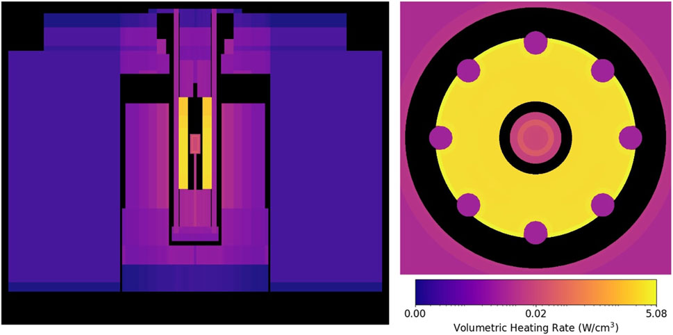
Figure 4. Volumetric heating rates of the KRUSTY geometry before thermal expansion. On the left is an YZ plot of the entire geometry, on the right is a focused XY plot around the fuel. Scale is in log units.
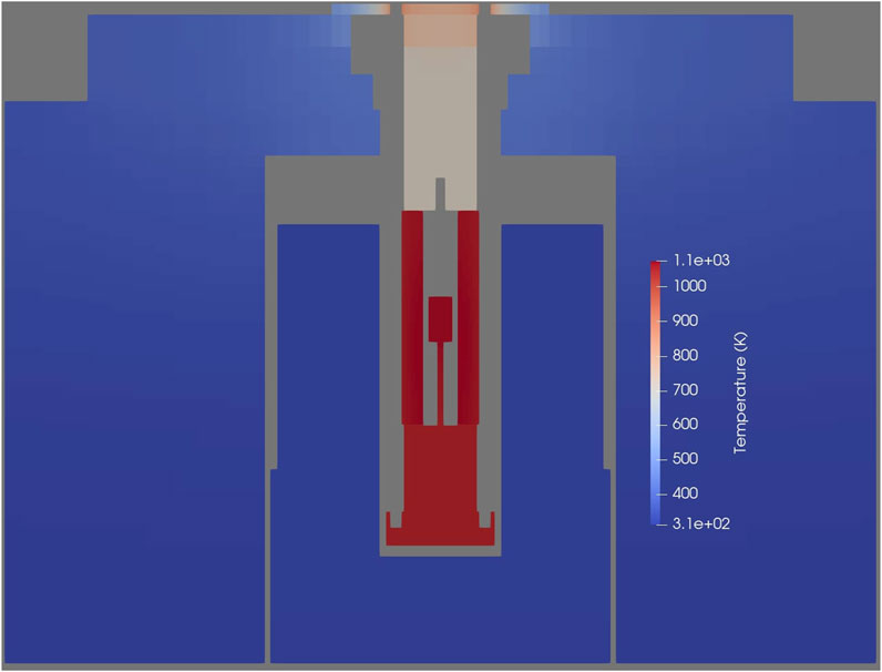
Figure 5. YZ slice of the KRUSTY geometry showing temperature before thermal expansion. The fuel has insulating boundary conditions on all sides, causing the thermal behavior in the axial reflectors.

Table 1. Change in material-based neutronic tallies due to thermal expansion. “sp” stands for source particle, as OpenMC tallies in eigenvalue mode are normalized per source particle.
The temperature profile in Figure 5 drives the thermal expansion seen in Figures 6, 7. The primary expansion occurs in the fuel, seeing a maximum of 25% volume increase in the edge cells of the fuel. Figure 7 shows that the radial expansion of the fuel is roughly 0.3 cm at its peak, and contracts in the center annulus at a slightly lower magnitude. As noted in Section 3.3, the necessary constraint on expansion at heat pipe boundaries potentially causes a more peaked radial expansion, and in real life the heat pipes would be pushed outwards as well. Besides the radial expansion of the fuel, there is also a general axial expansion in the central column of the reactor that pushes the top of the reactor upwards. Thermal expansion is negligible in the outer BeO reflectors and the further outer SS316 blocks.
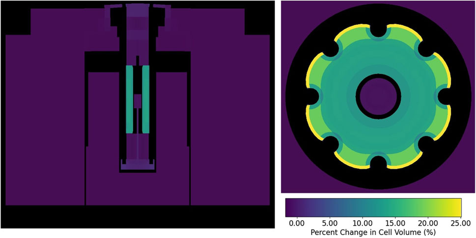
Figure 6. Percent changes in cell volume of the KRUSTY geometry after thermal expansion. On the left is a YZ plot of the entire geometry, on the right is a focused XY plot around the fuel.
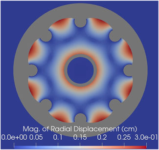
Figure 7. Displacement in the radial direction in units of centimeters, focused on the fuel region. Value is calculated by taking the square root of the sum of the squared X and Y displacements.
The neutronic effect of this expansion is significant for global neutronic parameters. Eigenvalue drops by 1,421 pcm to 0.98634
The reason for this strong effect has been referenced at the end of Section 2. Volumetric expansion makes a material seem more transparent to neutrons, and the more expansion the more transparent it appears. The UMo fuel has by far the largest expansion which increases neutron leakage from the fuel, particularly for fast neutrons, causing fewer fast fissions (raising thermal fission factor) and hardening the spectrum of the overall reactor. After expansion, the proportion of the flux that is thermal (less than 4 eV) fell by about 1%, while the flux proportion that is fast (greater than 0.1 MeV) grew by 4.2%.
This increased leakage from the fuel leads to changes in the absorption tallies, heating tallies, and power calculations for all materials in the core, seen in Table 1. Note that the absorption rate and heating tally are normalized per source particle, while power is normalized to a constant 5 kW. The fact that the total heating tally (energy deposited per source particle) decreased by 2.37% after expansion suggests that fission rate would need to be increased by a proportional 2.37% to maintain pre-expansion power. After power normalization, most of the power remains in the fuel, which only sees a roughly 7 W difference, which has mostly moved to the SS316 and BeO in the system. One other quantity to note is that boron carbide absorption rate increased by 2.9% after expansion. Increasing fission rate to maintain power would mean a nominal increase beyond 2.9% in actual absorptions per second for the absorber material. This could impact expected lifetime for the boron carbide.
Because of the upwards axial expansion in the center of the core, the highest leakage from the fuel is at the upper axial region. After power normalization, this results in an axial shift in the power of the fuel, seen in Figures 8, 9. The fuel is divided into six axial layers, the upper layer of which decreases in power by 5%, while the lowest layer increases in power by 2.5%. This spatial shift in power leads to a resulting change in temperature for the fuel, seen in Figures 10, 11. Both figures show a maximum decrease of 3.5 K in the fuel due to thermal expansion-induced power shift. This level of temperature change is unlikely to be of note to reactor designers, though the axial shift in power does mean that depletion calculations for the fuel may over-predict burnup at the top of the fuel and under-predict burnup at the bottom.
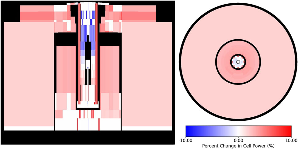
Figure 8. Percent change in normalized power for each cell in the KRUSTY reactor. On the left is a YZ plot, on the right is a XY plot. This figure assumes constant power pre and post-expansion. Values with relative standard deviations greater than 50% were excluded from the figure. Axial shift in power is caused by fast neutron leakage from the thermally expanded fuel.
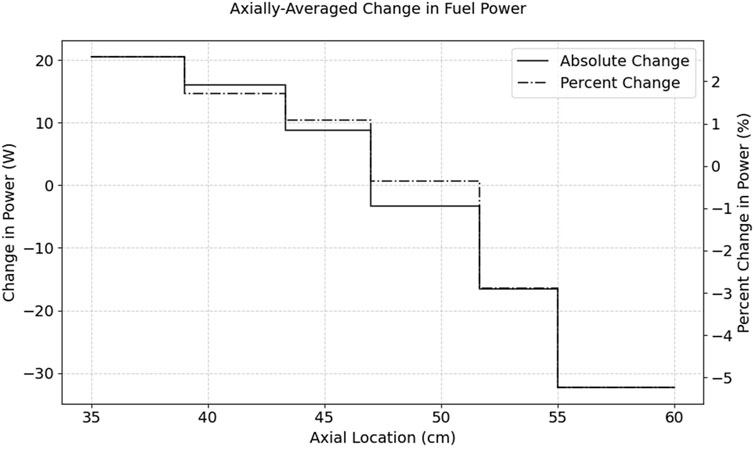
Figure 9. Absolute and percent change in axial power for the UMo fuel in the KRUSTY core as a result of thermal expansion. Axial shift in power is seen due to fast neutron leakage from expanded fuel.
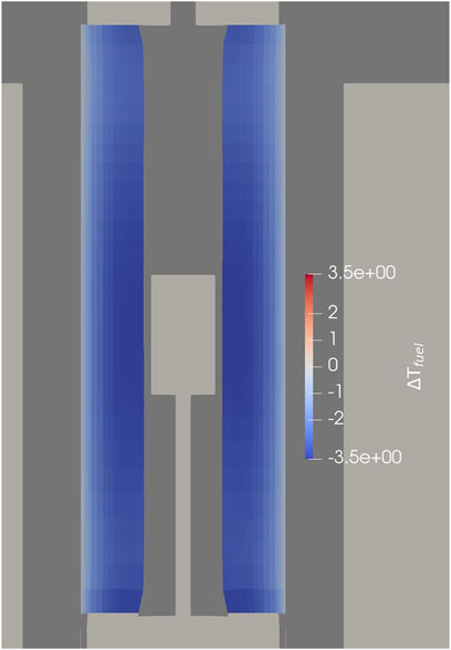
Figure 10. YZ slice of the fuel region showing change in fuel temperature due to changed neutronic heating rates post-thermal expansion. Comparison is against a model without thermal expansion.
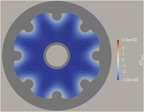
Figure 11. XY slice of the fuel region showing change in fuel temperature due to changed neutronic heating rates post-thermal expansion. Comparison is against a model without thermal expansion.
4.1 Heat pipe failure case
In order to evaluate if heat pipe failure changes any of these results, a “worst-case scenario” event was evaluated, where three neighboring heat pipes were simulated to have failed. This is done by removing the thermal boundary conditions at the heat pipe, essentially setting the derivative of the temperature to zero at that boundary. This does not change the material composition of the heat pipe, which in reality would change as the working fluid changed dynamics. The reason why this test is of interest to this work is because it introduces asymmetry to the thermal profile of the reactor, which in turn causes asymmetric thermal expansion. If the resulting thermal expansion difference is strong enough, it should drive a resulting asymmetric flux response and tilt the power in the system.
The three selected heat pipes can be seen in Figure 12 centered where the temperature increase is highest. The loss of cooling results in a maximum temperature increase of 100 K. As mentioned in Section 2, the fast spectrum reactor is less sensitive to changes in cross-section, so the dominant downstream effect is from increased thermal expansion. In this case that increased displacement is relatively minor, as seen in Figure 13. With a maximum increased displacement of 0.03 cm (compared to the non-failure expansion case), all neutronic and thermal downstream effects are essentially the same as reported for the non-heat pipe failure case. The thermal expansion of the fuel increasing from room temperature to an operating temperature of 1050 K is far greater than the thermal expansion due to a 100 K increase in temperature due to failed heat pipes, so this result makes sense.
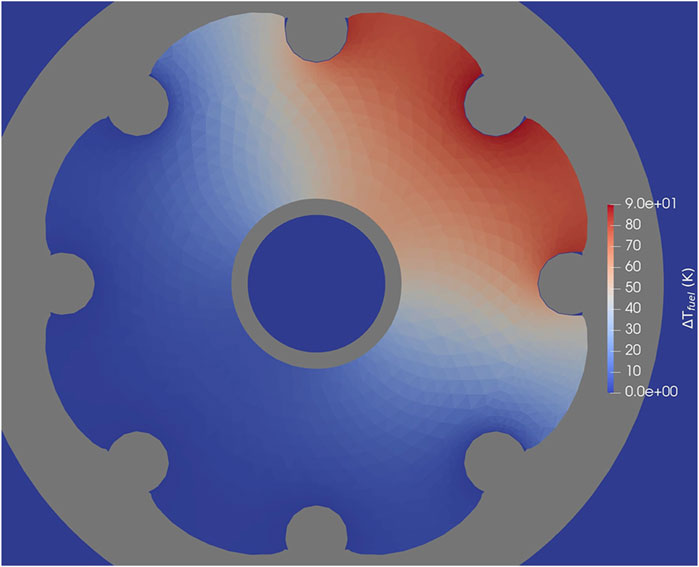
Figure 12. XY slice of the fuel region showing change in temperature of the triple heat pipe failure expansion case compared to the non-heat pipe failure expansion case.
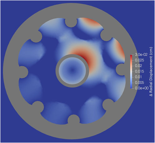
Figure 13. XY slice of fuel region showing comparison of displacement in the radial direction in the triple heat pipe failure expansion case compared to the non-heat pipe failure expansion case. Value is calculated by taking the square root of the sum of the squared X and Y displacements.
5 Conclusion
In summary, the net effect of thermal expansion is largely global. Significant eigenvalue and leakage impact was seen, but changes to the spatial distribution of heating were relatively minor. The only spatial shift in power that is of note is an axially downward shift in power in the UMo fuel. The increased leakage from thermal expansion of the fuel results in a loss of energy deposited in the system that would require a roughly 2.4% increase in fission rate to compensate, and global flux spectrum of the reactor is hardened by the increased leakage.
The coupled effect of including thermal expansion in the neutronic-thermal simulation loop finally results in a maximum 3.5 K difference in temperature reported in the fuel. A decrease of 3.5 K is less than would be discernible for most purposes, and would be unlikely to cause any alarm or secondary effects. This implies that for typical simulation of the core, the non-expanded geometry flux and temperatures are a good representation of the system. The impact on reactivity can be evaluated separately and included after the fact.
The effect of failure of heat pipes studied in Section 4.1 show that although heat pipe failure does introduce some tilt to the expansion of the system, the magnitude is too low to drive a noticeable effect on neutronic-thermal results. This result can be rationalized by recognizing that while the reported increase of 100 K is significant, it is small relative to the expansion of the fuel going from room temperature to operating temperatures at roughly 1050 K.
This work can be further improved in multiple areas. Firstly, the heat transfer in small air gaps needs to be properly accounted for in order to more accurately solve the heat transfer of the problem. That in turn makes the thermal expansion more accurate, and would have a minor impact on reducing particle leakage. Secondly, the mechanics solved on the mesh assume that all connected surfaces are “bound” together, when in reality they are often merely in contact with each other. The fuel and BeO reflector is a good example. When the fuel swells radially outwards, the BeO should not move with the fuel, but only resist movement normal to its surface. Finally, implementing heat pipe models to represent the heat removal in the system may change some of the results, particularly for the heat pipe failure case. Using Dirichlet boundary conditions with the heat pipe failures is like having perfect heat pipes that remove extra heat without increasing in temperature.
In a more general sense, this study shows good promise for the use of Monte Carlo simulation with deformed unstructured mesh geometries. While the coupling scheme described in Section 3.1 has limitations and is far from being user-friendly, the use of DAGMC with OpenMC is becoming more and more streamlined. Future problems that warrant solving neutronics in a highly complicated mesh environment will likely be solvable with the use of DAG-OpenMC.
Data availability statement
The raw data supporting the conclusions of this article will be made available by the authors, without undue reservation.
Author contributions
WK: Writing – original draft, Writing – review and editing. BF: Conceptualization, Funding acquisition, Supervision, Writing – review and editing.
Funding
The author(s) declare that no financial support was received for the research and/or publication of this article.
Acknowledgments
Thanks to Guillaume Giudicelli for his aid with MOOSE and to Patrick Shriwise for his development and stewardship of DAGMC.
Conflict of interest
The authors declare that the research was conducted in the absence of any commercial or financial relationships that could be construed as a potential conflict of interest.
Generative AI statement
The author(s) declare that no Generative AI was used in the creation of this manuscript.
Publisher’s note
All claims expressed in this article are solely those of the authors and do not necessarily represent those of their affiliated organizations, or those of the publisher, the editors and the reviewers. Any product that may be evaluated in this article, or claim that may be made by its manufacturer, is not guaranteed or endorsed by the publisher.
References
Adhikary, D. P., Jayasundara, C., Podgorney, R. K., and Wilkins, A. H. (2016). A robust return-map algorithm for general multisurface plasticity. Int. J. Numer. Methods Eng. 109, 218–234. doi:10.1002/nme.5284
Aldebie, F., Fernandez-Cosials, K., and Hassan, Y. (2024). Thermal-mechanical safety analysis of heat pipe micro reactor. Nucl. Eng. Des. 420, 113003. doi:10.1016/j.nucengdes.2024.113003
Andrews, N. C. (2012). Development of fission gas swelling and release models for metallic nuclear fuels. Ph.D. thesis, Massachusetts Institute of Technology Cambridge, MA.
Blacker, T. D., Bohnhoff, W. J., and Edwards, T. L. (1994). CUBIT mesh generation environment. Volume 1: users manual. Tech. Rep. Sandia Natl. Lab.(SNL-NM).
Cao, Y., Miao, Y., Mo, K., Stauff, N., and Lee, C. (2024). “Multiphysics simulations of the krusty criticality experiment using bluecrab,” in Physor 2024: beyond the blueprint: pioneering reactor physics for real-world implementation.
Chen, C., Mei, H., Wang, Z., Zhang, S., Liu, S., Wang, H., et al. (2023a). Study of the thermal expansion effects of a space nuclear reactor with an integrated honeycomb core design using openmc and ansys. Ann. Nucl. Energy 191, 109901. doi:10.1016/j.anucene.2023.109901
Chen, H., Wang, W., Wu, A., Zhang, K., Pan, R., Duan, W., et al. (2023b). Multi-physics coupling analysis of test heat pipe reactor krusty based on moose framework. Nucl. Eng. Des. 414, 112597. doi:10.1016/j.nucengdes.2023.112597
Coreform (2024). Neutronics on exact CAD geometry: advances in the Coreform Cubit DAGMC workflow. Available online at: https://coreform.com/news/neutronics-on-exact-cad-geometry-advances-in-the-coreform-cubit-dagmc-workflow/(Accessed July 1, 2024).
David, I., Poston, P. R. M., Gibson, M. A., and Sanchez, R. G. (2020). Results of the krusty warm critical experiments. Nucl. Technol. 206, S78–S88. doi:10.1080/00295450.2020.1727287
Davis, A., Shriwise, P., and Zhang, X. (2020). Dag-openmc: cad-based geometry in openmc. 395–398. doi:10.13182/T122-32104
Drezewiecki, T., Schmidt, J., Van Wert, C., and Clifford, P. (2021). “Fuel qualification for advanced reactors NUREG-2246,”. U.S. Nuclear Regulator Commission Rockville, MD.
Edenius, M. (1976). Studies of the reactivity temperature coefficient in light water reactors. Tech. Rep. Chalmers Tek. Hoegskola.
Gibson, M. A., Poston, D. I., McClure, P., Godfroy, T., Sanzi, J., and Briggs, M. H. (2018). “The kilopower reactor using stirling technology (krusty) nuclear ground test results and lessons learned,” in 2018 international energy conversion engineering conference, 4973.
Giudicelli, G., Lindsay, A., Harbour, L., Icenhour, C., Li, M., Hansel, J. E., et al. (2024). 3.0 - MOOSE: enabling massively parallel multiphysics simulations. SoftwareX 26, 101690. doi:10.1016/j.softx.2024.101690
Giudicelli, G. L., Abou-Jaoude, A., Novak, A. J., Abdelhameed, A., Balestra, P., Charlot, L., et al. (2023). The virtual test bed (vtb) repository: a library of reference reactor models using neams tools. Nucl. Sci. Eng. 197, 2217–2233. doi:10.1080/00295639.2022.2142440
Hu, G., Hu, R., Kelly, J., and Ortensi, J. (2019). Multi-physics simulations of heat pipe micro reactor. Tech. Rep. Argonne Natl. Lab.(ANL). doi:10.2172/1569948
Hubbard, M., Baines, M. J., and Jimack, P. (2009). Consistent dirichlet boundary conditions for numerical solution of moving boundary problems. Appl. Numer. Math. 59, 1337–1353. doi:10.1016/j.apnum.2008.08.002
Hughes, T. J., Engel, G., Mazzei, L., and Larson, M. G. (2000). The continuous galerkin method is locally conservative. J. Comput. Phys. 163, 467–488. doi:10.1006/jcph.2000.6577
Jamison, L., Stillman, J., Jaluvka, D., Mohamed, W., Kim, Y., and Wilson, E. (2020). Review of the technical basis for properties and fuel performance data used in HEU to LEU conversion analysis for U-10Mo monolithic alloy fuel. Tech. rep. Argonne, IL United States: Argonne National Lab.ANL.
Jeong, M. J., Im, J., Lee, S., and Cho, H. K. (2023). Multiphysics analysis of heat pipe cooled microreactor core with adjusted heat sink temperature for thermal stress reduction using openfoam coupled with neutronics and heat pipe code. Front. Energy Res. 11. doi:10.3389/fenrg.2023.1213000
Kendrick, W. R. (2024). Neutronic-thermal simulation of micro reactor designs for the purpose of analyzing the impact of thermal expansion and hydrogen migration in metal hydride moderator. Ph.D. thesis, Massachusetts Institute of Technology Cambridge, MA.
Lee, C., Jung, Y. S., Park, H., Shemon, E. R., Ortensi, J., Wang, Y., et al. (2021). Griffin software development plan. Tech. Rep. Ida. Natl. Lab.INL. doi:10.2172/1845956
LeVeque, R. J. (2002). Finite volume Methods for hyperbolic problems. Cambridge texts in applied mathematics. Cambridge University Press.
Lietzke, A. F. (1970). Simplified analysis of nuclear fuel pin swelling. National Aeronautics and Space Administration Washington, DC.
Ma, Y., Han, W., Xie, B., Yu, H., Liu, M., He, X., et al. (2021). Coupled neutronic, thermal-mechanical and heat pipe analysis of a heat pipe cooled reactor. Nucl. Eng. Des. 384, 111473. doi:10.1016/j.nucengdes.2021.111473
Oka, Y. (2013). Temperature effect of reactivity. Tokyo: Springer Japan, 23–33. doi:10.1007/978-4-431-54195-0_3
Pope, C., and Lum, E. (2020). “Nuclear reactor thermal expansion reactivity effect determination using finite element analysis coupled with Monte Carlo neutron transport analysis,” in Finite element methods and their applications. Editor M. Baccouch (Rijeka: IntechOpen Rijeka, Croatia). doi:10.5772/intechopen.93762
Poston, D. I., Gibson, M. A., Godfroy, T., and and, P. R. M. (2020a). Krusty reactor design. Nucl. Technol. 206, S13–S30. doi:10.1080/00295450.2020.1725382
Poston, D. I., Gibson, M. A., Sanchez, R. G., and and, P. R. M. (2020b). Results of the krusty nuclear system test. Nucl. Technol. 206, S89–S117. doi:10.1080/00295450.2020.1730673
Redmond, E. L. (1997). Multigroup cross section generation via Monte Carlo methods. Ph.D. thesis, Massachusetts Institute of Technology Cambridge, MA.
Romano, P. (2020). Heating and energy deposition. Available online at: https://docs.openmc.org/en/stable/methods/energy_deposition.html.
Romano, P. K., Horelik, N. E., Herman, B. R., Nelson, A. G., Forget, B., and Smith, K. (2015). Openmc: a state-of-the-art Monte Carlo code for research and development. Ann. Nucl. Energy 82, 90–97. doi:10.1016/j.anucene.2014.07.048
Rosenthal, J. S. (2000). Parallel computing and Monte Carlo algorithms. Far east J. Theor. statistics 4, 207–236.
Sanchez, R., Grove, T., Hayes, D., Goda, J., McKenzie, G., Hutchinson, J., et al. (2020). Kilowatt reactor using stirling technology (krusty) component-critical experiments. Nucl. Technol. 206, S56–S67. doi:10.1080/00295450.2020.1722553
Shemon, E., Miao, Y., Kumar, S., Mo, K., Jung, Y. S., Oaks, A., et al. (2023). Moose reactor module: an open-source capability for meshing nuclear reactor geometries. Nucl. Sci. Eng. 197, 1656–1680. doi:10.1080/00295639.2022.2149231
Springer, T. H., Tuttle, R. J., Otter, J. M., and Paschall, R. K. (1969). “Doppler and related measurements in a soft fast-reactor spectrum,” in Tech. Rep., north American aviation, inc., canoga park, CA (United States). Atomics International Div Conoga Park, CA. doi:10.2172/4784461
Stauff, N., Mo, K., Cao, Y., Thomas, J., Miao, Y., Zou, L., et al. (2021). “Detailed analyses of a triso-fueled microreactor: modeling of a micro-reactor system using neams tools,” in Tech. rep. Argonne, IL (United States): Argonne National Lab.ANL.
Sterbentz, J. W., Werner, J. E., McKellar, M. G., Hummel, A. J., Kennedy, J. C., Wright, R. N., et al. (2017). Special purpose nuclear reactor (5 MW) for reliable power at remote sites assessment report. Tech. Rep. Ida. Natl. Lab.(INL). doi:10.2172/1410224
Tautges, T. J., Wilson, P. P. H., Kraftcheck, J. A., Smith, B. M., and Henderson, D. L. (2009). “Acceleration techniques for direct use of CAD-based geometries in Monte Carlo radiation transport,” in M&C 2009 saratoga springs NY.
Walker, E., Skutnik, S., Wieselquist, W., Shaw, A., and Bostelmann, F. (2022). “SCALE modeling of the fast spectrum heat pipe reactor,” in Tech. rep. Oak Ridge, TN United States: Oak Ridge National Lab.ORNL.
Xiao, W., Li, X., Li, P., Zhang, T., and Liu, X. (2022). High-fidelity multi-physics coupling study on advanced heat pipe reactor. Comput. Phys. Commun. 270, 108152. doi:10.1016/j.cpc.2021.108152
Keywords: neutronics, multiphysics, microreactor, KRUSTY, openmc, MOOSE, thermal expansion
Citation: Kendrick WR and Forget B (2025) Coupled neutronic-thermal-mechanical simulation of the KRUSTY heat pipe microreactor. Front. Nucl. Eng. 4:1589780. doi: 10.3389/fnuen.2025.1589780
Received: 07 March 2025; Accepted: 17 April 2025;
Published: 29 April 2025.
Edited by:
Mark D. DeHart, Idaho National Laboratory (DOE), United StatesReviewed by:
Nicolas Stauff, Argonne National Laboratory (DOE), United StatesJohn Carter, Idaho National Laboratory (DOE), United States
Copyright © 2025 Kendrick and Forget. This is an open-access article distributed under the terms of the Creative Commons Attribution License (CC BY). The use, distribution or reproduction in other forums is permitted, provided the original author(s) and the copyright owner(s) are credited and that the original publication in this journal is cited, in accordance with accepted academic practice. No use, distribution or reproduction is permitted which does not comply with these terms.
*Correspondence: William Reed Kendrick, cmtlbmRyaWNAbWl0LmVkdQ==