 Liang Yang
 Jianhui Yang2
 Jakov Popov
 Andrew G. Buchan
- 1Faculty of Engineering and Applied Sciences, Cranfield University, Bedford, United Kingdom
- 2Voxshell Ltd, Cranfield University Technology Park, Bedford, United Kingdom
- 3School of Engineering and Materials Science, Queen Mary University of London, London, United Kingdom
Simulating neutronics and thermal hydraulics within nuclear reactor cores is computationally intensive, not only because of the complexity of the governing equations but also because of the intricate geometries involved. Solving the Boltzmann transport and Navier-Stokes equations for a full core representation typically relies on unstructured meshes, which, while highly flexible, can substantially increase computational costs regarding memory and solving time. Cartesian meshes with Finite Elements (FE) offer a faster alternative, potentially improving computational speed by an order of magnitude due to direct memory addressing. However, they necessitate finer grids to accurately capture the boundary details of non-Cartesian surfaces, which can offset these gains by increasing solver times. To address this challenge, a new meshing algorithm is proposed in conjunction with hybrid, matrix-based and matrix free, solver technologies. It employs a geometry-conforming boundary method using voxel-dominated Cartesian meshes. This method enables accurate boundary representation at arbitrary resolutions, which can be adjusted to resolve the physics to the desired level of accuracy rather than strictly to capture geometric detail. This is combined with a hybrid solver for fluid flows to different regions of a problem in order to increase efficiency when resolving the boundary. This article demonstrates the method’s application to Computational Fluids Dynamics (CFD) and neutronics problems relevant to reactor physics, showcasing its accuracy, convergence, numerical stability, and suitability for handling complex geometries.
Highlights
1 Introduction
Simulating neutron transport and thermal hydraulics within nuclear reactor cores is computationally intensive. The complexity of the governing equations combined with the intricate geometries involved often lead us to use simplifications, whether that be to the equations or the problem domains, that often sacrifices numerical accuracy for reduced computational costs. Often the thermal hydraulics are resolved at the sub-channel scale using coupled one-dimensional models that are highly parameterised and fine tuned to experimental data. Other examples include the use of diffusion theory for resolving the neutron distribution, perhaps with a few groups resolving the energy domain with smeared cross-sections homogenising the heterogeneous structures making a core.
High fidelity models are of course used today and are still being developed by various research bodies throughout the world to improve the quality of numerical approximations. Finite element, spectral element and control volume models are popular choices as they offer a flexible route to capturing geometries, and have been developed extensively over the last few decades. Examples of their use in thermal hydraulics include Paul et al. (2008), and similarly Fang et al. (2021), providing full FEM solutions of the Navier-Stokes LES equations for reactor analysis. Others have proposed hybrid methods, such as Liu et al. (2019), Liu et al. (2022), that aim to combine CFD calculations with sub-channel models to enhance accuracy whilst retaining the computational speed of the sub-channel model. A recent review of methods in CFD in nuclear thermal hydraulics can be found in Wang M. et al. (2021). Similarly, for neutron transport, FEM solutions on both structured (Evans et al., 2010) and unstructured grids (Wang Y. et al., 2021; Nguyen et al., 2025) have been developed and are in use in many industry and research codes and meshing tools (Tautges and Jain, 2012).
Unstructured mesh methods are best suited to handle complex geometries composing a core that include fuel pins, spacer grids among other supporting structures. Structured meshes, say with Finite Elements, have also been proposed as a faster alternative, offering the potential to improve computational speed by an order of magnitude due to their reduced memory access requirements and structured solver implementations. However, their primary limitation lies in handling complex geometries, particularly in the presence of curved boundaries and irregular features. Unlike unstructured meshes, which conform naturally to boundaries, Cartesian grids approximate curved surfaces with step-like edges. This stair-casing effect leads to significant accuracy loss, particularly in the BTE, where geometric fidelity plays a critical role in determining neutron streaming paths and scattering effects.
To mitigate the stair-casing issue, several Cartesian-based solver techniques have been developed for general PDEs, including applications in fluid flow, solid mechanics. These methods include:
Other approaches include the development of iso-parametric elements that can be used in combination with both structured and unstructured meshes to conform exactly to structures such including fuel pins (Owens et al., 2016).
From an implementation point of view, there are two ways to implement an FEA solver: the matrix-based method and the matrix-free method (Johan and Hughes, 1991; Davydov et al., 2020; Martínez-Frutos and Herrero-Pérez, 2015). The matrix-based approach assembles the global stiffness matrix, which can be memory-intensive for large sparse systems, and the assembly cost grows with the problem size. On the other hand, the matrix-free approach does not assemble the global matrix; instead, it computes matrix–vector products on the fly. This results in much lower memory usage and faster performance for large-scale problems, e.g., on GPUs.
There are two type of geometry modelling approaches, explicit modelling or implicit modelling. Explicit modeling describes geometry through direct parameterisation, where surfaces and boundaries are explicitly defined. This approach is widely used in Computer-Aided Design (CAD) systems, which rely on representations such as Non-Uniform Rational B-Splines (NURBS) and triangle meshes to create and manipulate complex structures.
Implicit modelling, on the other hand, defines geometry indirectly using mathematical functions, typically representing surfaces as level sets of scalar fields (Li et al., 2018). This approach is particularly advantageous for handling complex, topologically evolving shapes, such as those found in fluid simulations, medical imaging (MRI/CT scans), and volumetric datasets (e.g., VDB data (Museth, 2013)). It can be generated via implicit geometry kernel or library, including nTop Inc. (2024), LEAP71 (2024).
This article explores implicit geometric modelling techniques, specifically by leveraging the signed distance function (SDF) to efficiently represent complex geometries. In addition, the proposed method addresses the challenge of using structured meshes that still conform to geometries of arbitrary shape. The method (named implicit geometry-conforming meshing (IGCM)) employs a voxel-dominated Cartesian mesh, that maintains as much structure as possible, but for a few elements that are perturbed so that element surfaces are fitted to an internal body’s boundary, or a problem’s exterior domain. In addition, this article also proposes a hybrid solver for CFD that, in particular, can be used in combination with the meshing tool. This approach ensures a balance between computational efficiency and geometric fidelity, allowing fine-scale resolution where necessary while maintaining the performance benefits of a structured mesh. In contrast to the hex-core meshing algorithm, the mesh will be exported in unstructured format. Our solver will leverage the Cartesian data structure and design the associated solver.
The following sections are set out as follows. Section 2 details the voxel dominated meshing tool together with the hybrid solver for CFD. Section 3 presents a range of numerical examples applying the proposed tools to a range of applications and benchmarks including neutron transport and CFD of fuel assemblies. Section 4 completes the article with a conclusion.
2 Voxel dominated mesh with hybrid solver
This section describes the voxel-dominated displaced boundary mesh method, along with the hybrid solver for efficient CFD simulations.
Two variants of the meshing approach are proposed for capturing the geometric details of arbitrary bodies. The first applies when only the external or internal region of the domain is needed, such as in CFD calculations for flow around solid bodies. The second resolves both the internal and external regions of a structure, which is typically required for neutron transport and fluid-structure interaction calculations. This approach is often referred to as multi-material with interface.
In both cases, the goal is to preserve a uniform Cartesian grid across as much of the domain as possible, modifying or displacing elements only where necessary to conform to the surface of the body. The method is illustrated in Figure 1, which shows a Cartesian voxel mesh initially discretising a square domain containing a circular region whose surface is to be preserved. Maintaining the Cartesian structure throughout but filtering out the internal elements of the circle (assuming here the exterior is to be resolved) results in the mesh of 1b where clearly the surface is approximated with the step-like structure and resemblance of the surface is only achieved when sufficient, and perhaps excessive, resolution is applied.

Figure 1. (a) Initial voxel grid with circle indicated; (b) Cartesian mesh with internal elements removed; (c) Unfitted boundary method for external domain with mixed Cartesian and unstructured grid; (d) Unfitted boundary method preserving internal/external domains using only quadrilateral elements in Cartesian coordinates.
Instead, the method introduced here begins with structured Cartesian voxel mesh (or background mesh) of Figure 1a with element size
From this, a transformation map,
In Equation 1 the term
The set of nodes
For neutron transport problems, the solution domain includes both internal and external regions relative to a surface—such as when resolving fuel pins and surrounding moderator. In this situation, meshes must preserve the volumes of both internal and external regions. To achieve this, the method presented here uses the SDF function, as before, to define distances between a surface and the nodes of an initial background Cartesian mesh. The initial node movement described in Equation 1 is again applied; however, internal elements of the body are retained. At this stage, modified elements surrounding the surface either preserve the surface along an edge or have the surface cutting through their volume. In the former case, no more modifications are necessary. In the latter case, a further modification is applied to the element’s nodes to preserve the surface while maintaining the quadrilateral structure of the overall mesh. A single node not in contact with the surface is identified and moved onto it. As presented in Figure 1d, the resulting mesh preserves both the surface and the Cartesian quadrilateral mesh structure.
2.1 Hybrid region FEM solver
For time dependent CFD solutions, a hybrid matrix-based and matrix-free solver is implemented for the proposed voxel-dominant meshes that is composed of a structured (Cartesian) and unstructured component. More specifically, the domain
For the Cartesian mesh region
For the unstructured mesh region
The solver treats each region separately, where for the Cartesian grid it employs the previous work developed in Yang et al. (2016), Yang et al. (2019), Nillama et al. (2022). In essence this is a stabilised explicit, matrix-free, solver designed to reduce memory access cost of indirect addressing by relying on the structured nature of the grid. For the unstructured grid component, the solver relies on matrix-based approaches which, whilst fast, does require more memory. However, due to the voxel-dominant mesh structure, the unstructured part is restricted to the interface/boundary region which is typically a small proportion of the whole domain. Thus the larger proportion of the domain is treated with minimal storage. Overall, this may provide an even balance of memory usage and efficient computation.
3 Numerical results
This section provides a number of numerical examples using the proposed methods in diffusion-based applications, CFD and neutron transport to demonstate the accuracy and stability.
3.1 Poisson problem: circle embedded in a square domain with analytical solution
This numerical example evaluates the accuracy of the proposed meshing method in solving Poisson’s equation, given by:
where the solution variable
The problem is defined over a square domain
On the outer square boundary, a Dirichlet boundary condition is applied to match the analytical solution:
The problem is solved on two different mesh types: 1. Voxel-Dominated Mesh–A geometry-conforming mesh where the circular boundary is fully resolved. 2. Standard Cartesian Mesh–A structured Cartesian grid where elements overlapping with the circle are removed.
The computed solutions and errors for both mesh types, using a
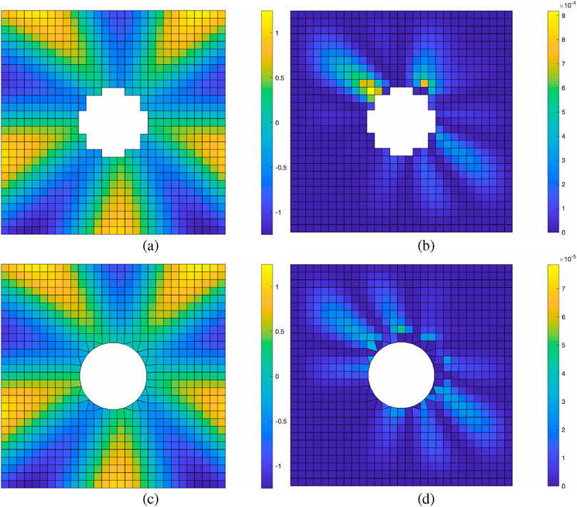
Figure 2. (a,b) Solution and error using the voxel grid. (c,d) Solution and error using the voxel-dominant grid. Both sets of results are based on a
This improvement is further illustrated in Figure 3, which plots the solution along the horizontal line at
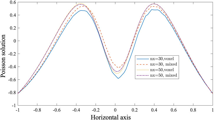
Figure 3. Solution along the horizontal line at
In the two simulations presented, the solver iterations (see Section 3.6) required to reach convergence were closely comparable. The voxel and voxel-dominant meshes required 80 and 82 solver iterations for tolerance
3.2 Fixed source neutron transport simulation of fuel pin and PWR assembly
This numerical example provides a demonstration of the meshing tool for use in resolving neutron transport problems at the pin-level scale. The analysis is focused on the ability of the meshing tool to capture domain surfaces accurately, but which also remains numerically stable when used in combination with typical FEM discretisations. For this demonstration both the single energy group fixed source and multi-group eigenvalue versions of the Boltzmann transport equations are solved. The latter of these is given by,
for
In the following analysis standard numerical technques for discretising the space-angle dimensions of the BTE are employed. This includes a discontinuous Galerkin FEM spatial discretisation using bi-linear basis functions on quadrilateral element meshes. This is combined with a simple, zero-order structured discrete ordinate-
The first demonstration uses a 2-dimensional single fuel pin of radius 0.418 cm, encapsulated within a square domain, with side lengths 1.26 cm, bounded by reflective surfaces. Two sets of single group cross-sections and neutron sources are used which are not designed to represent anything physical but, moreover, are used to test numerical stability using the geometry capturing meshes over different material regimes. In both problems, the material and sources in the fuel and moderator remain constant, as listed in Table 1, with the scattering and total cross-sections set to examine mesh performance in the transparent and diffuse material regimes. As the analytical solutions yield a constant flux, it would be expected the solutions to be resolved to within machine precision and solver tolerances, regardless of the mesh resolution. Thus numerical instabilities arising from the mesh and element shape will most likely be exposed when capturing the circular pin geometry. Noting that all calculations were performed using double precision, this investigation is not focused on other instabilities, causing solution divergence, including those due to poor element shape and lower precision computations. Figure 4 present the absolute relative scalar flux errors using meshes ranging from FEM grids of
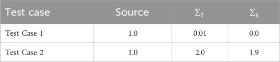
Table 1. Source and material cross-sections used in the neutron transport test cases.
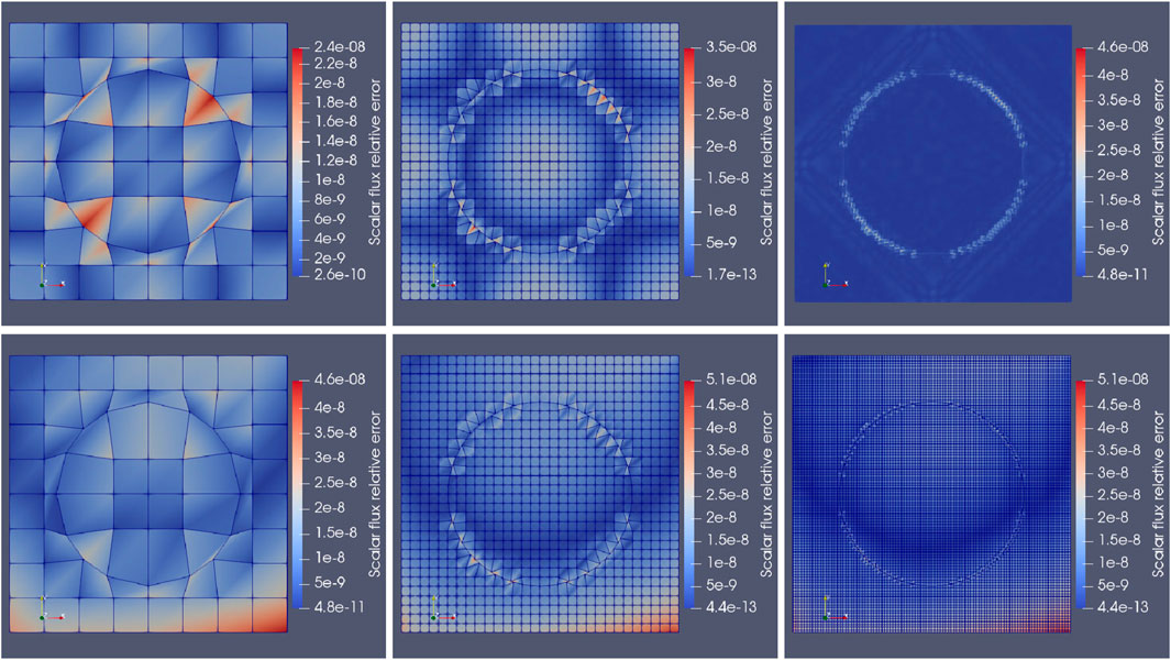
Figure 4.
The following investigation evaluates mesh performance in resolving fuel pins within a representative reactor geometry. A single fuel pin and its surrounding moderator were modeled using the dimensions and material cross-sections for uranium dioxide (
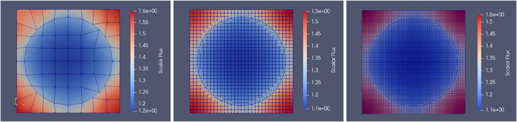
Figure 5.
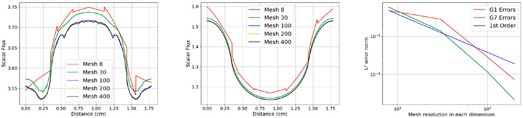
Figure 6. Left and middle:
In summary, this numerical example provides evidence the meshing algorithm is suitable for resolving fuel pins across transparent and diffuse material regimes, and for those typical found in reactor physics benchmarks.
3.3 Two dimensional CFD benchmark
The 2D lid-driven cavity flow (Ghia et al., 1982) at
To validate the hybrid solver, we rotate the computational domain by 45°, intentionally introducing a stair-casing issue. This test evaluates the solver’s ability to handle both Cartesian and unstructured grids while ensuring accurate vorticity transport and solution consistency.
Figure 7 presents the computational meshes and their corresponding velocity solutions under a
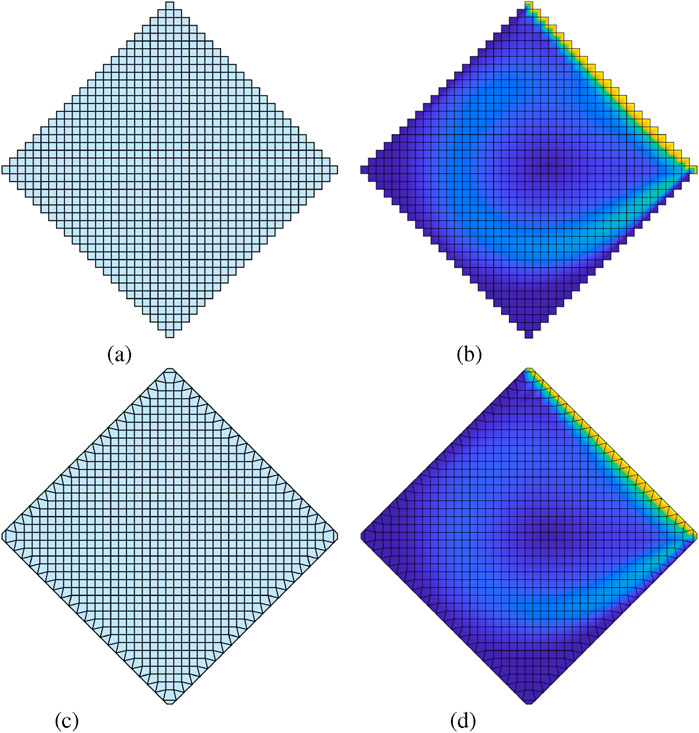
Figure 7. Lid driven flow benchmark case for
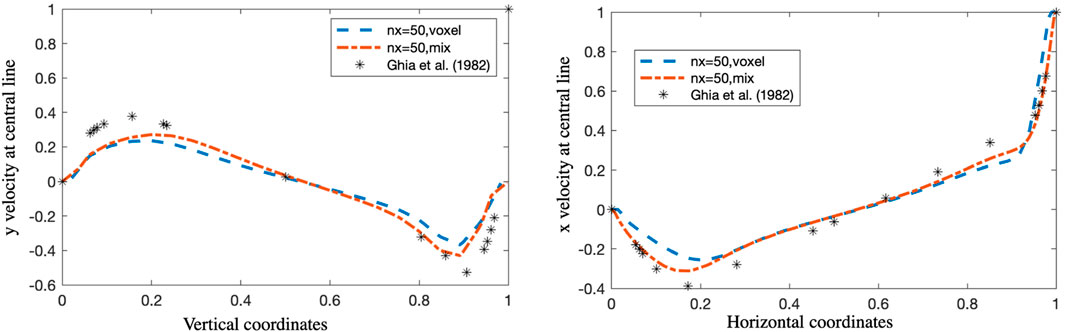
Figure 8. Vertical and horizontal velocity through the horizontal centerline and vertical of the cavity at Re = 1,000 using n = 50 solution in the original coordinates before rotation.
3.4 Three dimensional CFD CANDU fuel assembly
This study presents a CFD analysis of a three-dimensional CANDU fuel assembly (Torgerson et al., 2006), focusing on pressure distribution and velocity profiles. The CANDU (Canada Deuterium Uranium) reactor utilizes heavy water moderation, with fuel bundles immersed in pressurized coolant. Accurately modeling the flow behavior around the fuel rods is essential for optimising heat transfer efficiency and minimising pressure drop (Piro et al., 2016).
A typical CANDU fuel bundle, illustrated in Figure 9, consists of 37 fuel elements, concentrically arranged and mounted on two end plates. The bundle has a total length of approximately 500 mm and a diameter of about 100 mm. The CFD simulation provides insights into velocity distribution, flow separation, and pressure variations within the assembly. These results help assess flow uniformity and identify potential recirculation zones, ensuring an optimized thermal-hydraulic performance of CANDU fuel bundles during reactor operation. The simulation is conducted for a single-phase flow, excluding heat transfer and chemical reactions.
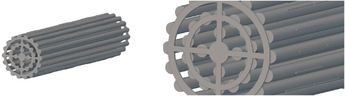
Figure 9. Isometric view of a 37 element CANDU fuel bundle modelled in nTOP, left: whole view, right: close view.
To analyse the effects of mesh resolution, surface and volume meshes were generated at three levels of refinement with mesh size of 0.2868 cm, 0.1434 cm, 0.0717 cm, with a refinement factor of two at each level. Figure 10 shows the surface and volume meshes at three resolutions. All simulations used a mass flow rate of 20.9 kg/s as used in (Bhattacharya et al., 2012). The pressure drop for each simulation of increasing mesh resolutions was calculated as 11.22 KPa, 11.02 kPa, 10.78 kPa showing these values to be converging to within 0.2 kPa. Figure 11 presents the flow velocities pressure profiles using the small and large meshes. Again, this shows closely converging solution details.
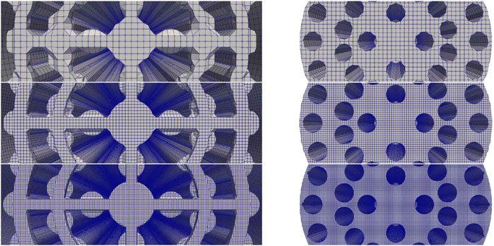
Figure 10. Surface and volume meshes at three resolutions: 0.2868 cm, 0.1434 cm, and 0.0717 cm, corresponding to a refinement factor of two between successive levels.
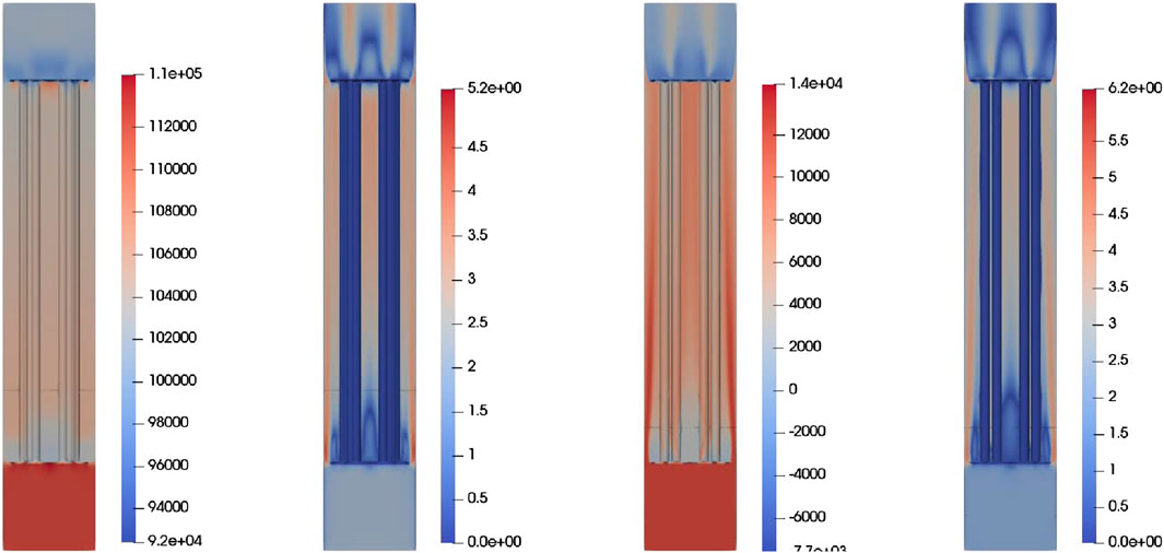
Figure 11. Contour plots of pressure distribution and velocity magnitude at coarse (0.2868 cm) and fine (0.0717 cm) grid resolutions, under a mass flow rate of 20.9 kg/s. Left: coarse grid results. Right: fine grid results.
3.5 Illustration of computational efficiencies
The use of meshes constructed predominantly of structured elements offer significant memory savings compared to fully unstructured meshes, in part this is due to the absence of indirect addressing and mesh-connectivity storage. Additionally, the repetition of element shapes eliminates the need to compute and store spatial integrals for each individual element. Although quadrilateral and hexahedral elements involve more nodes per element, the overall number of elements is substantially lower, by factors of approximately 6 in 2D and 20 in 3D, resulting in a net reduction in memory and computational costs. Thus the effectiveness of the method presented will be driven by the fraction of unperturbed elements.
Table 2 presents the fraction of unperturbed elements used in the 2D reactor pincell problems and the 3D CANDU reactor geometry for varying mesh sizes. In the 2D case, the number of unperturbed element is quite low for the smallest mesh, the eight by eight grid resulting in just 25% of elements being unperturbed. However, one can see from Figure 5 the pin occupies a large proportion of the domain and so the large elements tend to intersect the surface on a regular basis. As mesh resolution is increased the unperturbed fraction quickly rises and reaches over 93% for the 100 by 100 mesh. Similarly the three meshes used for the CANDU geometry show increasing unperturbed fractions, initially starting from 51% for the lowest mesh of 300.5 K elements, and rising to 85% for the large mesh with 20.2 M elements.
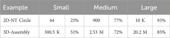
Table 2. Fraction of perturbed elements for the 2D neutron transport and 3D CANDU reactor.
3.6 CFD and BTE solver information
The CFD and BTE solver used here was based on an in-house code (Buchan et al., 2021), written in Fortran-90 and compiled as a python library. The CFD solver used a continuous linear FEM with VMS stabilisation, and a generalized minimal residual method (GMRES) solver with a Jacobi preconditioner. The BTE solver used discontinuous linear FEM with a sweep based solutions scheme. For the eigenvalue problems, a Power method was employed. Both solvers have been developed with MPI parallelism and the CFD solver has the additional OpenMP capability which was used in the calculation of the CANDU assembly.
4 Conclusion
This study presents a hybrid solver framework integrated with a voxel-dominated Cartesian meshing approach to efficiently solve the Boltzmann Transport Equation and Navier-Stokes equations in complex nuclear reactor simulations. Traditional unstructured meshing techniques, while flexible, impose significant computational burdens due to high memory consumption and solver inefficiencies. In contrast, structured Cartesian methods offer computational advantages but suffer from stair-casing errors, particularly in handling curved geometries.
To overcome these limitations, the implicit geometry-conforming meshing (IGCM) method was introduced within a voxel-dominated Cartesian mesh. This approach is coupled with a hybrid solver, applying structured solvers in voxel regions while using adaptive numerical treatments near complex boundaries. The combination of these methods enables high computational efficiency while preserving accuracy in neutron transport and thermal hydraulics simulation. The demonstration provided here showed that complex geometries can be resolved through the simulation of a CANDU assembly. The proposed hybrid solver and meshing framework provides a promising direction for accelerating full-core reactor simulations while ensuring the accuracy of boundary interactions. Future work will focus on benchmarking the solver against high-fidelity reference solutions and extending its applicability to multi-physics coupling, including neutron transport, thermal radiation, and turbulence modelling.
Data availability statement
The raw data supporting the conclusions of this article will be made available by the authors, without undue reservation.
Author contributions
LY: Software, Writing – original draft, Formal Analysis, Funding acquisition, Methodology. JY: Methodology, Writing – review and editing. JP: Formal Analysis, Writing – review and editing. AB: Funding acquisition, Methodology, Software, Writing – original draft.
Funding
The author(s) declare that financial support was received for the research and/or publication of this article. STFC funded through grant: Parallel solvers for voxel-dominant meshes for the Boltzmann Transport Equation.
Acknowledgments
Authors acknowledge the support of the STFC-funded Digital BIC program. The authors thank nTOP for providing the free academic license to use CAD modelling software to model the CANDU fuel bundle.
Conflict of interest
Authors LY and JY were employed by Voxshell Ltd.
The remaining authors declare that the research was conducted in the absence of any commercial or financial relationships that could be construed as a potential conflict of interest.
Generative AI statement
The author(s) declare that no Generative AI was used in the creation of this manuscript.
Any alternative text (alt text) provided alongside figures in this article has been generated by Frontiers with the support of artificial intelligence and reasonable efforts have been made to ensure accuracy, including review by the authors wherever possible. If you identify any issues, please contact us.
Publisher’s note
All claims expressed in this article are solely those of the authors and do not necessarily represent those of their affiliated organizations, or those of the publisher, the editors and the reviewers. Any product that may be evaluated in this article, or claim that may be made by its manufacturer, is not guaranteed or endorsed by the publisher.
References
Adigun, B. J., Buchan, A. G., Adam, A., Dargaville, S., Goffin, M. A., and Pain, C. C. (2018). A haar wavelet method for angularly discretising the boltzmann transport equation. Prog. Nucl. Energy 108, 295–309. doi:10.1016/j.pnucene.2018.05.023
Barad, M. F., Colella, P., and Schladow, S. G. (2009). An adaptive cut-cell method for environmental fluid mechanics. Int. J. Numer. methods fluids 60, 473–514. doi:10.1002/fld.1893
Bhattacharya, A., Yu, S., and Kawall, G. (2012). Numerical simulation of turbulent flow through a 37-element candu fuel bundle. Ann. Nucl. energy 40, 87–105. doi:10.1016/j.anucene.2011.10.017
Buchan, A. G., Yang, L., Welch, D., Brenner, D. J., and Atkinson, K. D. (2021). Improved estimates of 222 nm far-uvc susceptibility for aerosolized human coronavirus via a validated high-fidelity coupled radiation-cfd code. Sci. Rep. 11, 19930. doi:10.1038/s41598-021-99204-0
Davydov, D., Pelteret, J.-P., Arndt, D., Kronbichler, M., and Steinmann, P. (2020). A matrix-free approach for finite-strain hyperelastic problems using geometric multigrid. Int. J. Numer. Methods Eng. 121, 2874–2895. doi:10.1002/nme.6336
Evans, T. M., Stafford, A. S., Slaybaugh, R. N., and and, K. T. C. (2010). Denovo: a new three-dimensional parallel discrete ordinates code in scale. Nucl. Technol. 171, 171–200. doi:10.13182/NT171-171
Fang, J., Shaver, D. R., Tomboulides, A., Min, M., Fischer, P., Lan, Y.-H., et al. (2021). Feasibility of full-core pin resolved cfd simulations of small modular reactor with momentum sources. Nucl. Eng. Des. 378, 111143. doi:10.1016/j.nucengdes.2021.111143
Ghia, U., Ghia, K. N., and Shin, C. (1982). High-re solutions for incompressible flow using the navier-stokes equations and a multigrid method. J. Comput. Phys. 48, 387–411. doi:10.1016/0021-9991(82)90058-4
Ingram, D. M., Causon, D. M., and Mingham, C. G. (2003). Developments in cartesian cut cell methods. Math. Comput. Simul. 61, 561–572. doi:10.1016/s0378-4754(02)00107-6
Johan, Z., and Hughes, T. J. (1991). A globally convergent matrix-free algorithm for implicit time-marching schemes arising in finite element analysis in fluids. Comput. Methods Appl. Mech. Eng. 87, 281–304. doi:10.1016/0045-7825(91)90009-u
LEAP71 (2024). PicoGK: a compact and robust open-source geometry kernel for computational engineering.
Lesueur, M., Rattez, H., and Colomés, O. (2022). μct scans permeability computation with an unfitted boundary method to improve coarsening accuracy. Comput. and Geosciences 166, 105118. doi:10.1016/j.cageo.2022.105118
Li, Q., Hong, Q., Qi, Q., Ma, X., Han, X., and Tian, J. (2018). Towards additive manufacturing oriented geometric modeling using implicit functions. Vis. Comput. Industry, Biomed. Art 1, 9–16. doi:10.1186/s42492-018-0009-y
Liu, B., He, S., Moulinec, C., and Uribe, J. (2019). Sub-channel cfd for nuclear fuel bundles. Nucl. Eng. Des. 355, 110318. doi:10.1016/j.nucengdes.2019.110318
Liu, B., He, S., Moulinec, C., and Uribe, J. (2022). A multiscale model of a rod bundle using subchannel cfd. Nucl. Eng. Des. 393, 111793. doi:10.1016/j.nucengdes.2022.111793
Martínez-Frutos, J., and Herrero-Pérez, D. (2015). Efficient matrix-free gpu implementation of fixed grid finite element analysis. Finite Elem. Analysis Des. 104, 61–71. doi:10.1016/j.finel.2015.06.005
Martorell, P. A., and Badia, S. (2024). High order unfitted finite element discretizations for explicit boundary representations. J. Comput. Phys. 511, 113127. doi:10.1016/j.jcp.2024.113127
Meinke, M., Schneiders, L., Günther, C., and Schröder, W. (2013). A cut-cell method for sharp moving boundaries in cartesian grids. Comput. and Fluids 85, 135–142. doi:10.1016/j.compfluid.2012.11.010
Museth, K. (2013). Vdb: high-resolution sparse volumes with dynamic topology. ACM Trans. Graph. (TOG) 32, 1–22. doi:10.1145/2487228.2487235
Nguyen, K. H., DeHart, M. D., Hanophy, J. T., and Wang, Y. (2025). Development of a griffin model of the advanced test reactor. Ann. Nucl. Energy 211, 111012. doi:10.1016/j.anucene.2024.111012
Nillama, L. B. A., Yang, J., and Yang, L. (2022). An explicit stabilised finite element method for navier-stokes-brinkman equations. J. Comput. Phys. 457, 111033. doi:10.1016/j.jcp.2022.111033
nTop Inc (2024). nTop documentation, release 4.0: implicit and other models. nTop Inc. Available online at: https://ntop.com.
Nuclear Energy Agency (2003). NEA/NSC/DOC(2003)16. Paris, France: Nuclear Energy Agency, Organisation for Economic Co-operation and Development.
Owens, A., Welch, J., Kópházi, J., and Eaton, M. (2016). Discontinuous isogeometric analysis methods for the first-order form of the neutron transport equation with discrete ordinate (sn) angular discretisation. J. Comput. Phys. 315, 501–535. doi:10.1016/j.jcp.2016.03.060
Paul, F., Fischer, J. W. L., and Kerkemeier, S. G. (2008). nek5000 web page. Available online at: http://nek5000.mcs.anl.gov.
Peskin, C. S. (2002). The immersed boundary method. Acta Numer. 11, 479–517. doi:10.1017/s0962492902000077
Piro, M., Wassermann, F., Grundmann, S., Leitch, B., and Tropea, C. (2016). Progress in on-going experimental and computational fluid dynamic investigations within a candu fuel channel. Nucl. Eng. Des. 299, 184–200. doi:10.1016/j.nucengdes.2015.07.009
Salih, S. Q., Aldlemy, M. S., Rasani, M. R., Ariffin, A., Ya, T. M. Y. S. T., Al-Ansari, N., et al. (2019). Thin and sharp edges bodies-fluid interaction simulation using cut-cell immersed boundary method. Eng. Appl. Comput. Fluid Mech. 13, 860–877. doi:10.1080/19942060.2019.1652209
Tautges, T. J., and Jain, R. (2012). Creating geometry and mesh models for nuclear reactor core geometries using a lattice hierarchy-based approach. Eng. Comput. 28, 319–329. doi:10.1007/s00366-011-0236-8
Torgerson, D., Shalaby, B. A., and Pang, S. (2006). Candu technology for generation iii+ and iv reactors. Nucl. Eng. Des. 236, 1565–1572. doi:10.1016/j.nucengdes.2006.04.020
Verzicco, R. (2023). Immersed boundary methods: historical perspective and future outlook. Annu. Rev. Fluid Mech. 55, 129–155. doi:10.1146/annurev-fluid-120720-022129
Wang, M., Wang, Y., Tian, W., Qiu, S., and Su, G. (2021a). Recent progress of cfd applications in pwr thermal hydraulics study and future directions. Ann. Nucl. Energy 150, 107836. doi:10.1016/j.anucene.2020.107836
Wang, Y., Schunert, S., Ortensi, J., Laboure, V., DeHart, M., Prince, Z., et al. (2021b). Rattlesnake: a moose-based multiphysics multischeme radiation transport application. Nucl. Technol. 207, 1047–1072. doi:10.1080/00295450.2020.1843348
Xie, Z. (2022). An implicit cartesian cut-cell method for incompressible viscous flows with complex geometries. Comput. Methods Appl. Mech. Eng. 399, 115449. doi:10.1016/j.cma.2022.115449
Yang, L. (2018). One-fluid formulation for fluid–structure interaction with free surface. Comput. Methods Appl. Mech. Eng. 332, 102–135. doi:10.1016/j.cma.2017.12.016
Yang, L., Badia, S., and Codina, R. (2016). A pseudo-compressible variational multiscale solver for turbulent incompressible flows. Comput. Mech. 58, 1051–1069. doi:10.1007/s00466-016-1332-9
Yang, L., Gil, A. J., Carreño, A. A., and Bonet, J. (2018). Unified one-fluid formulation for incompressible flexible solids and multiphase flows: application to hydrodynamics using the immersed structural potential method (ispm). Int. J. Numer. Methods Fluids 86, 78–106. doi:10.1002/fld.4408
Keywords: hybrid matrix and matrix-free solver, reactor physics, finite element, CFD, neutron transport, voxel-dominated meshing
Citation: Yang L, Yang J, Popov J and Buchan AG (2025) Hybrid solvers for reactor modelling: matrix-based and matrix-free approaches on voxel-dominated meshes. Front. Nucl. Eng. 4:1597165. doi: 10.3389/fnuen.2025.1597165
Received: 20 March 2025; Accepted: 19 September 2025;
Published: 15 October 2025.
Edited by:
Mark D. DeHart, Abilene Christian University, United StatesReviewed by:
Julian Duran, Karlsruhe Institute of Technology (KIT), GermanyGlenn Sjoden, The University of Utah, United States
Copyright © 2025 Yang, Yang, Popov and Buchan. This is an open-access article distributed under the terms of the Creative Commons Attribution License (CC BY). The use, distribution or reproduction in other forums is permitted, provided the original author(s) and the copyright owner(s) are credited and that the original publication in this journal is cited, in accordance with accepted academic practice. No use, distribution or reproduction is permitted which does not comply with these terms.
*Correspondence: Liang Yang, bGlhbmcueWFuZ0BjcmFuZmllbGQuYWMudWs=; Andrew G. Buchan, YS5idWNoYW5AcW11bC5hYy51aw==