 Stefan Finsterle
 Matthew Waples
 Mengzhu Yang3
- 1Finsterle GeoConsulting, LLC, Kensington, CA, United States
- 2Deep Isolation Nuclear, Inc., Berkeley, CA, United States
- 3The University of Sheffield, Sheffield, United Kingdom
The performance of a deep borehole repository for the disposal of radioactive waste may be affected by the generation of hydrogen gas produced by the corrosion of the steel canisters and the borehole casing. In particular, the evolution of a free gas phase may lead to high overpressures within the borehole and near field of the repository, displacing radionuclides dissolved in pore water, and facilitating the transport of volatile radionuclides. These processes are analyzed by numerical modeling of non-isothermal, multiphase flow and transport of hydrogen gas and water in a generic deep horizontal borehole repository completed in an argillaceous host rock. The near-field submodel addresses gas generation within and outside the canister and the effect of canister breach on near-field pressure and saturation distributions; a repository-scale model examines the effect of gas generation in a long disposal section. The models support canister and design decisions for deep borehole repositories. The simulations reveal the significance of the repository design on gas flow, both on the local scale of the components of the engineered barrier system, and on the larger scale of the repository layout. It can be concluded that for a typical design of a deep horizontal borehole repository, corrosion gases are contained within the disposal section of the borehole, or effectively dissipate into the repository’s near field without generating excessive overpressures that affect the integrity of the engineered barrier system or the overall performance of the repository.
1 Introduction
The safe disposal of radioactive waste in a deep geologic repository relies on the performance of multiple engineered and natural barriers whose general functions are to immobilize and confine the waste, retain the radionuclides or reduce their release, and to isolate the repository from the accessible environment by placing it into a stable geologic formation. This overall disposal concept applies to both a conventional mined repository as well as borehole repositories, including a deep horizontal borehole repository in an argillaceous host rock (Muller et al., 2019; Finsterle et al., 2019). The fate of corrosion gases generated in a narrow borehole repository surrounded by a tight formation is of particular interest and is therefore the main topic of this study.
The generation of gases (mainly hydrogen) from the corrosion of the waste canister and the borehole casing may have direct and indirect implications for the performance of the engineered barrier system (EBS) and therefore the safety of the repository. The effectiveness with which gas dissipates along the borehole and penetrates the host rock determines the repository-induced pressure buildup, which may detrimentally affect the barrier functions of the EBS and the near field. Understanding, predicting, managing, and mitigating the impact of corrosion gases on repository performance is essential, affecting choices regarding canister materials, the design of buffers and seals as well as the overall repository layout.
The fact that gas is being generated often leads to the need for a trade-off in design decisions. For example:
• The use of alternative, lower-cost canister materials with lower yield strength may necessitate greater shell thickness to withstand prevailing hydrostatic or stacking pressures. The alternative material may also have a higher stoichiometric volume of gas for a similar amount of alloy. Both of these changes would lead to increased gas generation that may damage the integrity of the engineered and near-field barriers.
• Similarly, seals are typically designed to isolate a disposal section of the repository by preventing leakage of contaminated fluids. As a result of the seal’s low permeability, the pressures may build up considerably within the repository, unless the seal allows the gas to escape while at the same time preventing the transmission of liquid.
• Pressurization of the disposal section could be mitigated by providing sufficient pore volume for gas accumulation, either in dedicated structures or within the buffer. However, this may negatively affect the barrier function of the buffer (e.g., reducing its thermal conductivity or increasing its permeability or effective diffusion coefficient).
• In a borehole repository, a casing is installed for borehole stability and operational requirements. As will be discussed below, an intact casing traps corrosion gas, leading to overpressures in the space between the canister and the casing. These overpressures could be mitigated by perforating the casing. However, the perforations could affect the casing’s straightness and smoothness, which is essential for the emplacement and potential retrieval of the canisters.
Various corrosion processes and the associated gas generation rates have been extensively studied for different canister materials. The impact of the local environment, specifically temperature, pH, Eh, and pore water composition that lead to accelerated corrosion or the development of a repassivation layer have been analyzed by analytical and numerical investigations, laboratory studies, long-term field experiments in underground research laboratories, and natural analogue studies as a basis for identifying suitable canister materials and for estimating their longevity under repository conditions; for comprehensive reviews, see Rodwell et al. (1999) and King et al. (2024a). Furthermore, the impact of gas generation on the safety of individual barrier components has been analyzed for mined repositories by means of laboratory and field experiments (Croisé et al., 2006; Jacops et al., 2014), detailed process modeling (Marschall et al., 2005; Senger et al., 2008; Xu et al., 2008; Croisé et al., 2011; Avis et al., 2014; Vehling et al., 2024) as well as using numerical performance assessment models to calculate the effects of gas on the repository scale (Nagra, 2004a; Nagra, 2004b; Nagra, 2008; Nagra, 2016; Diomidis et al., 2016; NWMO, 2018; King et al., 2024b). Most of these modeling studies focus on gas dissipation into the host formation or along the access structures of a mined repository to examine the risk that overpressurization leads to failure of the engineered and near-field barrier system. Special topics (such as the impact of gas generation on bentonite resaturation, the creation of dilatant pathways, the tranport of volatile radionuclides, and the evolution of relative humidity near the canister surface) have been analyzed in coupled process models typically using idealized geometrical representations. Moreover, the fate of corrosion gases in a very deep, vertical borehole repository has been discussed in (Nirex (2004); Brady et al. (2009); Grundfelt and Crawford (2014).
Gas generation and the evolution and migration of a free gas phase within the repository depends on the waste type, canister design and material, overall repository concept, and site-specific conditions. Repositories for low- and intermediate-level wastes (L/ILW) originates from various sources, including operational waste, maintenance activities, research, and power plant decommissioning that contain considerable amounts of steel and scrap metals as well as organic materials, producing significantly more gas than high-level waste (HLW) or spent nuclear fuel (SNF). In this analysis, we only consider gas generation issues for the disposal of HLW and SNF, waste forms that are contained in metallic canisters, which are the main sources of hydrogen gas generation as they corrode.
The corrosion resistance and total iron content of the canister materials affect, respectively, the rate and total amount of gas being generated. Duplex steel canisters are used for waste disposal in boreholes. The overall repository concept and thermodynamic conditions determine both the gas generation rate, the evolution of a free gas phase, and its dissipation. Gas generation in a repository located in the unsaturated (notably at Yucca Mountain) does not pose any adverse effects. Conventional mined repositories, while located in the saturated zone, are depressurized and ventilated during the operational period, and are typically surrounded by an unsaturated bentonite buffer. These oxidizing conditions affect the corrosion and thus gas generation rate—specifically during the early phase with elevated temperatures—but also provide gas storage capacity due to the high compressibility of the air initially present in the buffer and backfill materials. By contrast, borehole repositories are in a fully saturated, anoxic environment under high pressures. Given that the depth of a borehole repository exceeds 1 km, which leads to higher hydrostatic pressures than encountered in a mined repository, more of the generated hydrogen is dissolved in the pore water. Once the solubility limit is exceeded, a free gas phase evolves, which must displace liquid (rather than just compress gas). The high-pressure conditions also lead to high gas densities, keeping the free gas volume per mass of generated hydrogen small.
The presence or absence of bentonite, cementitious materials, and metallic components (such as an overpack or casing) within the disposal cavity not only determines the chemical environment and thus the corrosion rate, but also influences the ease with which gas can dissipate. In a mined repository, the thick bentonite buffer and concrete liners affect the pH conditions, form a hydraulic barrier, and provide pore volume for gas storage. In the current horizontal borehole repository design (Muller et al., 2019), there is no buffer or backfill, i.e., the canisters are in direct contact with drilling or emplacement fluids, which could be engineered to reduce corrosion. (Note that the access hole is assumed backfilled).
While no explicit barrier function is assigned to the casing (which is needed for borehole stability and facilitating emplacement and potential retrieval of the canisters), it is an additional source of corrosion gas. Moreover, during the early disposal period, the casing prevents gas from escaping the annulus between the canister and the casing. The cement between the casing and the borehole wall affects the chemical environment of the canister only after the casing has been breached.
This discussion highlights that there are considerable differences between gas generation issues in a minded and deep borehole repository, leading to different effects and thus different design options to mitigate their consequences. While the role of corrosion gas has been extensively studied for mined repositories, there is a need to examine its effects in deep borehole repositories. Specifically, we examine the details of the evolution and migration of a free hydrogen gas phase near the corroding canister surfaces—both inside and outside the canister—using a high-resolution representation of a segment of the disposal section of a slighty inclided horizontal borehole repository. Pressure, temperature, and phase partitioning effects unique to a deep borehole repository located in the saturated zone are evaluated, including the impact of a high pressure gradient established between the outside and inside of the canister upon its failure. In addition, gas transport on the repository scale is simulated with an accurate representation of the components within the borehole, accounting for thermal, hydrological, and bouyancy forces that drive the dissipation of the corrosion gas. The combination of the simulation studies address key gas-related safety issues in the context of radioactive waste disposal in deep borehole repositories.
The overall goal of the work presented in the current study is to extend the understanding of the migration of hydrogen generated by the corrosion of waste canisters and the borehole casing in a deep horizontal borehole repository sited in an argillaceous host rock. Non-isothermal two-phase flow simulations are employed to examine the local impacts of gas generation within a short section of the disposal borehole, followed by an analysis of its behavior and composite impact on the repository scale.
2 Model setup
2.1 Conceptual model
The conceptual model describes the abstraction of the engineered repository components and the features of the geosphere, along with the physical processes considered relevant for simulating the evolution of the repository system in response to the generation of decay heat from the waste and gas from the corrosion of the canisters and the casing. The decision to which degree of detail these features and processes are to be implemented in the numerical model depends on the purpose of the model. As discussed above, it is expected that gas generation impacts the system state both locally on the scale of a few canisters, but also globally on the scale of the borehole repository’s long disposal section and surrounding near field. First, a high-resolution model of a short borehole section with only a few canisters is developed. Based on the insights gained from this local analysis, a repository-scale model then examines the overall system response to gas generation and its dissipation along the borehole and into the near field.
The key processes considered in this study are nonisothermal flow of hydrogen and water in both the aqueous and gaseous phases within the engineered components of the borehole repository and the surrounding geologic formation. Flow of liquid and gas is described by the two-phase extension of Darcy’s law, driven by viscous, capillary, and gravity forces. Relative permeability and capillary pressure functions are based on the van Genuchten formulation as given by Luckner et al. (1989). Hydrogen dissolves in the liquid phase according to Henry’s law, i.e., potential supersaturation and bubble nucleation affecting the emergence of a free gas phase are not considered. Water is present in the gas phase according to its temperature-dependent saturated vapor pressure. Binary diffusion of hydrogen and water in both phases is considered. Heat is transported by conduction, convection, and diffusion, also accounting for latent heat effects during phase changes. Thermal conductivity is a linear function of saturation. Porosity changes linearly as a function of pore pressure and temperature using a volumetric pore compressibility and thermal expansivity.
The geochemical reactions related to the corrosion of the canisters and casing or those occurring in the cement and near field formation are not explicitly included in the simulations. However, the rate of water consumption by corrosion is implemented through a simple stochiometric relation to the time-dependent gas generation rates. Furthermore, gas generation and water consumption rates are related to gas saturation, and corrosion ceases altogether as the contact zones around the canisters and casing dry out.
The host rock is assumed to be homogeneous, which is a potentially limiting simplification. Specifically, gas generation itself may lead to complex geomechanical processes in an argillaceous formation (such as pathway dilation, fracturing, and associated clay swelling and shrinking effects), which could induce new or amplify existing heterogeneities and related gas flow processes (Marschall et al., 2005; Faybishenko et al., 2022; Finsterle et al., 2025).
A rigorous but pragmatic validation approch should be used to test the appropriateness of the conceptual model and its limiting assumptions.
The coupled nonlinear algebraic mass- and energy-balance equations (with pressure, temperature, and hydrogen mass fractions in each grid block as the unknown primary variables) are solved simultaneously using Newton-Raphson iterations. The elements of the Jacobian matrix are calculated numerically. The set of linear equations arising at each Newton-Raphson iteration are solved using an iterative sparse matrix solver. Details about the physical processes and the corresponding mathematical model can be found in the documentation of the TOUGH2 code (Pruess et al., 2012), which is implemented in the iTOUGH2 simulation-optimization framework (Finsterle et al., 2017) used for this study.
2.2 Discretization
The finite volume method used for the spatial discretization of the model domain provides considerable flexibility in local mesh refinement, which is essential when attempting to represent components with dimensions between the centimeter scale (such as the thickness of the casing) and the kilometer scale (such as the regional geological features) in a single, integrated performance assessment model.
The geometrical parameters of each repository element represented in the model are summarized in Table 1. The surface areas and volumes of the canister and casing determine the gas generation rates and total amount of hydrogen being produced, as further discussed in Section 2.4. The canister spacing determines the average gas and heat generation rate per meter of borehole. We assume that one canister is emplaced every 6 m. If canisters were emplaced with a different spatial frequency f (canisters per meter), the average gas and heat generation rates would be changed by a factor of
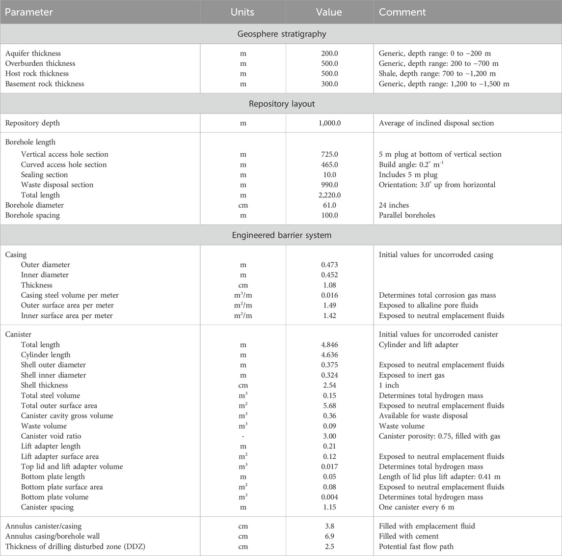
Table 1. Geometric parameters of geosphere, repository, and engineered barrier system.
For the local model of a short section of the borehole and the surrounding near field, a two-dimensional, radial (2-DR) model is developed, with the axis inclined upwards by an angle of 3° from horizontal, which is part of the repository design as discussed below. The reduction of the real, three-dimensional (3-D) system to a lower dimension of 2-DR is justifiable by recalling that (a) all the geometrical components of the borehole repository are axisymmetric, (b) the dominant flow processes of advective and diffusive gas transport as well as convective and conductive heat dissipation occur radially or are aligned with the borehole, and (c) radial permeabilities are very low, making advective and convective processes insignificant and allowing gravitational forces to be ignored, while (d) the potentially much higher axial permeabilities—specifically within the two annuli of the borehole and the drilling disturbed zone (DDZ), which may lead to advective and convective flow in axial direction—are fully accounted for. This hybrid model reduces numerical errors by eliminating the anisotropy in numerical dispersion of radially propagating saturation, concentration, and temperature fronts. The model domain and its discretization are shown in Figure 1A. It represents only 4.5 canisters at the end of the borehole repository’s inclined disposal section. The local model consists of 3,306 elements and 6,469 connections between them.
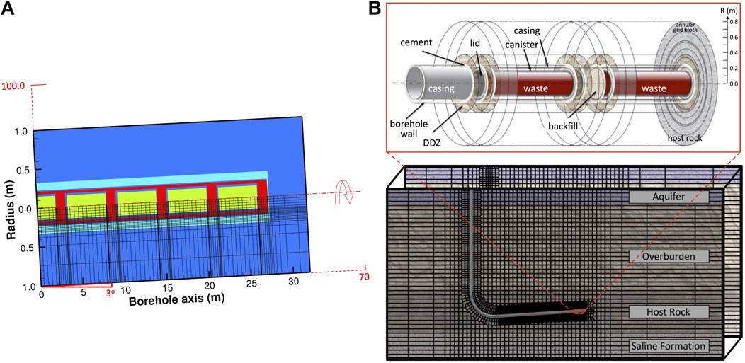
Figure 1. (A) Two-dimensional, radial (2-DR) discretization of local model; (B) 2-DR near-field model embedded in 3-D repository-scale model.
For the regional-scale model, a coarser version of the local 2-DR model up to a radial distance of 10 m is embedded in a conventional Cartesian model of the geosphere (Figure 1B), capturing both the cylindrical near-field effects and the 3-D processes in the far field. The 1 km long disposal section contains 166 individually represented waste canisters, each holding a single spent fuel assembly from an AP1000 pressurized water reactor (PWR) at 55 GWd/t burn-up. This computationally efficient hybrid discretization method has been successfully applied to the simulation of both horizontal and vertical borehole repositories (Muller et al., 2019; Finsterle et al., 2019; 2021a; 2021b). The regional-scale model consists of 31,570 elements and 91,797 connections between them. Three equations—one for water, hydrogen, and heat—are solved in each element, resulting in a degree of freedom of 94,710. Time stepping is dynamically adjusted based on the convergence behavior of the Newton-Raphson iteration, with an initial time step of 1 s that increases to a few years during the early, transient gas and heat generation phase, and a few tousand years as it approaches steady state.
2.3 Material properties, initial and boundary conditions
Properties of the main engineered and natural materials are listed in Table 2. For this generic analysis, typical values are selected for the host formation, specifically a relatively low permeability associated with a correspondingly high gas entry pressure. While each material is associated with a full set of thermal and hydrological parameters affecting two-phase flow of gas and liquid as well as conductive and convective heat transport, only a small subset of these parameters is provided, selected based on their significance for the storage and flow of fluids and heat within the respective material. The properties of the aquifer, overburden, and deep formation below the host rock have no significant impact on gas migration, which is controlled by the components of the EBS and near-field properties of the shale; these properties are therefore not listed or further discussed here. Note, however, that they affect the long-term migration of radionuclides, as discussed in Finsterle et al. (2020).
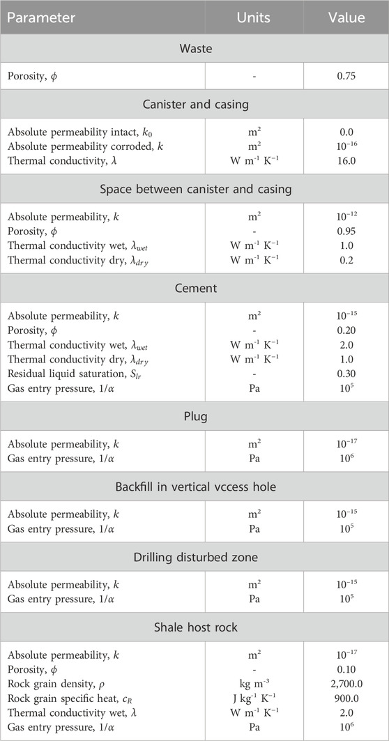
Table 2. Relevant material properties.
Thermodynamic properties of water and steam, specifically pressure- and temperature-dependent densities, viscosities, internal energies, and saturated vapor pressures, are calculated based on steam table equations (IAPWS, 2007). The density of gaseous hydrogen is calculated from the ideal gas law. Viscosity and solubility are interpolated from experimental data given in Vargaftik (1975).
All boundaries of the local model are closed with the exception of the vertical boundary to the right, where a constant pressure of 10 MPa and constant temperature of 42 °C is specified, corresponding to the approximate hydrostatic pressure and ambient temperature at the repository depth of 1 km. The entire model is initialized as fully liquid saturated, with the exception of the open space within the canister, which is assumed to be filled with an inert gas at a pressure of 0.25 MPa, i.e., above atmospheric due to the thermal expansion of the gas, which is heated to a temperature of 90 °C during the pre-emplacement storage period.
The repository-scale model is initialized by steady-state calculations, which establishes a hydrostatic pressure profile that accounts for liquid densities as a function of pressure and temperature with a surface temperature of 10 °C and geothermal gradient of 30 °C/km. The initial conditions within the canister are identical to those of the local model.
Corrosion gas and heat generation are specified as time-dependent source terms, as discussed in the next subsection.
2.4 Corrosion, gas and heat generation rates
Upon emplacement of the canisters into the borehole repository, which is filled with ambient pore water, drilling mud, or a specially engineered emplacement fluid, anoxic conditions are assumed to be present and maintained, reducing the general corrosion rate but also having a deleterious effect on repassivation. Under these conditions, the following reaction describes general corrosion and the associated generation of hydrogen:
Equation 1 applies to both materials involved, i.e., Alloy 2205 duplex stainless steel for the canister and a generic carbon steel (akin to Alloy 1,018 steel) for the casing. Though Alloy 2205 duplex stainless steel is only approximately 70% iron by mass, and carbon steel is often above 95% iron by mass, both the canister and casing materials are assumed to be 100% iron for conservatism and simplicity.
The borehole fluid is assumed effectively neutral, with a relatively high salinity of 2 g/L (henceforth referred to as “brine”). This concentration of chlorides accelerates the general corrosion rate (Khalaf et al., 2025). Phenomena such as stress corrosion cracking are not explored due to the lack of tensile loading upon emplacement. Similarly, other phenomena are either not credited or assumed of second order for the estimation of conservative general corrosion rates. These phenomena include microbially induced corrosion, which may at least be delayed due to excessive temperatures in the first hundred years and further impeded by engineered barriers such as the cement surrounding the casing. Moreover, the transformation of H2 to CH4 in clays, passivation, radiolysis, and the generation of radon formed by the radioactive decay of uranium, thorium, and radium are not accounted for in this study.
Corrosion rates in Table 3 are derived from Nagra (1994). It is understood that corrosion rates depend (among other factors) on the evolution of pore water pH, relative humidity (affected by temperature, saturation, matric potential, and water availability), and chemical reactivity of the material the steel is in contact with (Wieland et al., 2020). In this study, we assume that gas production rates are constant in time and independent of changing near-field conditions or the development of a passivation layer. Nevertheless, as a sensitivity case, we include the dependence of gas generation on local water availability according to the approximation described in Croisé et al. (2011); see discussion in Section 3.4 below.
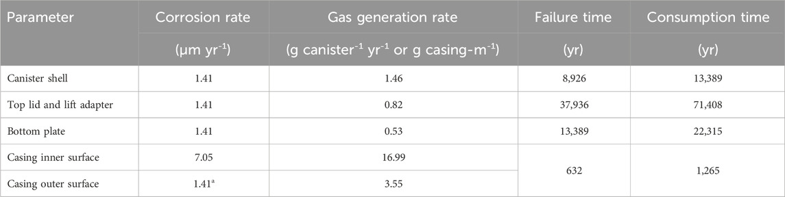
Table 3. Corrosion and gas generation rates, and times of failure and consumption.
The chosen rates were experimentally shown to be conservative (Waples et al., 2025). The experiment involved a 30-day corrosion test of Alloy 2205 duplex stainless steel and 1018 carbon steel coupons. The coupons were immersed in a chamber flooded with a 2 g/L brine pressurized to 42 MPa and heated to 191 °C. The resulting corrosion rates were no higher than 0.50 μm/yr for Alloy 2205 duplex stainless steel and 4.74 μm/yr for 1,018 carbon steel. Galvanic couples of the two alloys were also tested and measured; none of those coupons exhibited rates higher than those mentioned above. For conservatism, however, this model retains the higher corrosion rates listed in Table 3.
Using the assumed corrosion rates from Table 3 and the geometries from Table 1, the temporal reduction of casing and canister shell thicknesses as well as other canister components are predicted. For this model, failure or breach is assumed to occur once the component’s thickness is half of its initial value. After casing failure, the canisters are assumed to be subjected to lithostatic pressures and may no longer be retrievable, though they may still maintain containment until their failure time. These failure times correspond to 632 and 8,926 years for the casing and canister shell, respectively.
Following failure, the ferrous components would continue corroding, generating hydrogen until complete consumption of the component. As water enters the canister once it is breached, corrosion also occurs on its inside surface, effectively doubling the gas generation rate. Notably, due to its relatively large thickness of 19 cm, the canister lid would be the last component to be fully consumed at 71,408 years after emplacement. After this time, there would be no more man-made metal materials for water to react with. It is worth noting that this conceptualization of corrosion conservatively assumes a sufficient supply of water or brine. Without replenishment, the water initially present in the borehole disposal section will have been fully consumed by corrosion reactions after approximately 4,500 years. This estimate does not account for radiolysis and assumes constant surface contact with corroding metals. Without water replenishment, canisters would have approximately 75% of their original thickness at the time of water depletion. For this model, however, it is assumed that sufficient water becomes available from the saturated formation, an assumption that is conservative regarding the amount and rate of gas being generated. Lastly, the contents of the canisters are not factored into the corrosion and gas generation model.
The decaying waste also generates heat. Each canister is assumed to house the fuel rods from an assembly of a Westinghouse AP1000 pressurized water reactor after 10 years of cooling in a spent fuel pool. (To dispose of the entire AP1000 assembly rather than just the fuel rods, a slightly longer canister would need to be fabricated, reducing the overall heat output per borehole length.) The assemblies are assumed to have around 4.0% enrichment and a burn-up of 55 GWd/t. Each assembly contains 0.5465 tons of heavy metals, which results in an initial heat release at the time of waste emplacement (after the 10-year cooling period) of 1.12 kW per canister (Gibb et al., 2008). The reduction in heat released by each canister, shown in Figure 2, is supplied as a time-dependent, volume-specific source term to all computational elements of the numerical model that represent a canister.
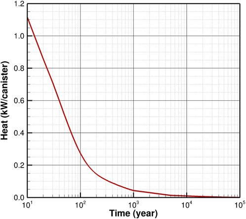
Figure 2. Decay heat released by each canister as a function of time.
3 Simulation results
3.1 Canister-scale model
3.1.1 Early system evolution
We first present the results from the smaller-scale, high-resolution model of a short disposal section at the end of the horizontal borehole. Figure 3 shows the parallel evolution of gas saturation, temperature, and pore pressure during the first 100 years after waste emplacement. Initially, the formation is fully liquid saturated at the ambient temperature of 42 °C and the hydrostatic pressure of 10 MPa. By contrast, the void space within the canister is gas filled at a temperature of 90 °C and a pressure of 0.25 MPa. The generation of hydrogen due to corrosion starts immediately after emplacement on all metal surfaces exposed to water. Even after a relatively short time of 1 year, a free gas phase evolves within the confined space between the canisters and the casing. The accumulating gas is pushed towards the end of the borehole, where it leaks around the casing into the cement-filled annulus between the casing and the borehole wall, displacing water in the opposite direction. Small amounts of gas also penetrate the host rock.
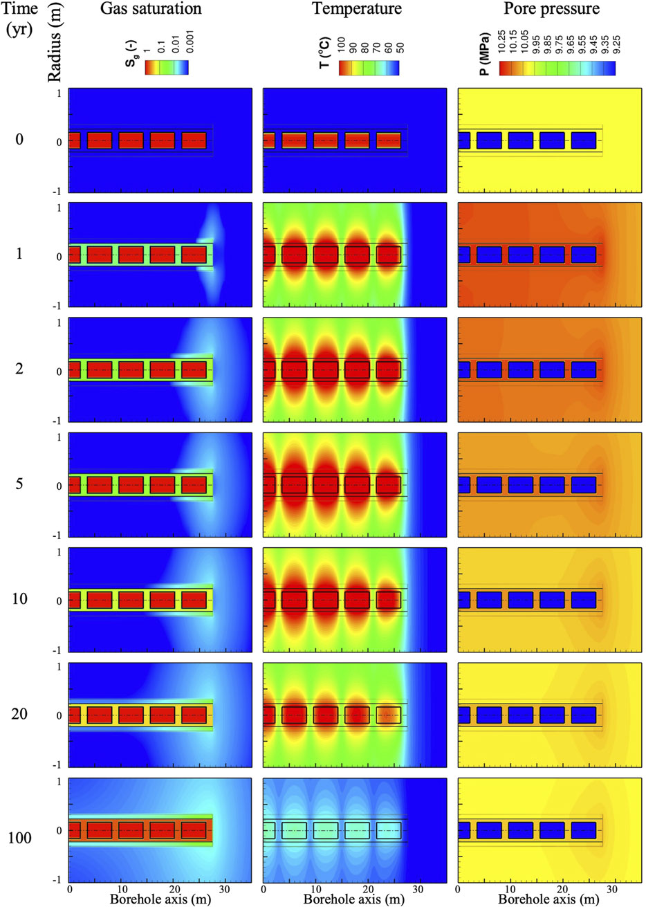
Figure 3. Evolution of gas saturation, temperature, and pore pressure during the first 100 years (radial direction is exaggerated by a factor of 10 to borehole axis).
The heat generated by radioactive decay is largest immediately after waste emplacement, heating up the borehole and the host rock in its the vicinity. While the maximum temperature reaches 117 °C, no boiling occurs due to the high pore pressures in the formation; the pressure within the canister increases slightly to 0.33 MPa in response to the thermal expansion of the gas. Heat dissipation into the formation quickly exceeds the exponentially decreasing heat generation rate (see Figure 2) such that temperatures start declining after about 4 years. The thermal period lasts for approximately 500 years, after which temperatures have recovered to the ambient condition prior to the repository-induced thermal perturbation.
Pore pressures are affected by both temperature changes and gas generation. Heat migrates relatively fast due to the relatively high thermal diffusivity of the formation. Given the thermal expansion of the pore fluids in combination with the low permeability of the host rock results in a considerable pressurization of the system. During the cooling period, this build-up reverses itself due to fluid contraction. Nevertheless, the early-time pressure evolution is dominated by these thermal effects, with pressurization from gas generation only becoming visible after about 10 years, where gas generation initially only pressurizes the fluids confined within the casing, and later along the cement-filled annulus, and finally in the host rock in regions where a free gas phase evolves.
3.1.2 Impact of casing and canister failure
Figure 4 shows the continuation of essentially the same trends as described above. However, the casing failure at 632 years allows gas to escape radially from the location where it is generated (rather than flowing at accumulated rates inside the casing to the end of the borehole). As a result, both the pressure and gas saturation distribution quickly assume cylindrical shapes with reduced maximum values. As gas release to the host rock is now spread over a larger area, and hydrogen generation from the corrosion of the casing stops after 1,265 years, the dissolution of hydrogen in the liquid phase and its radial diffusion away from the borehole exceeds the generation rate, thus reducing the gas saturation in the host rock. After 4,000 years, the system is again fully liquid saturated, and overpressures caused by the free gas phase have dissipated.
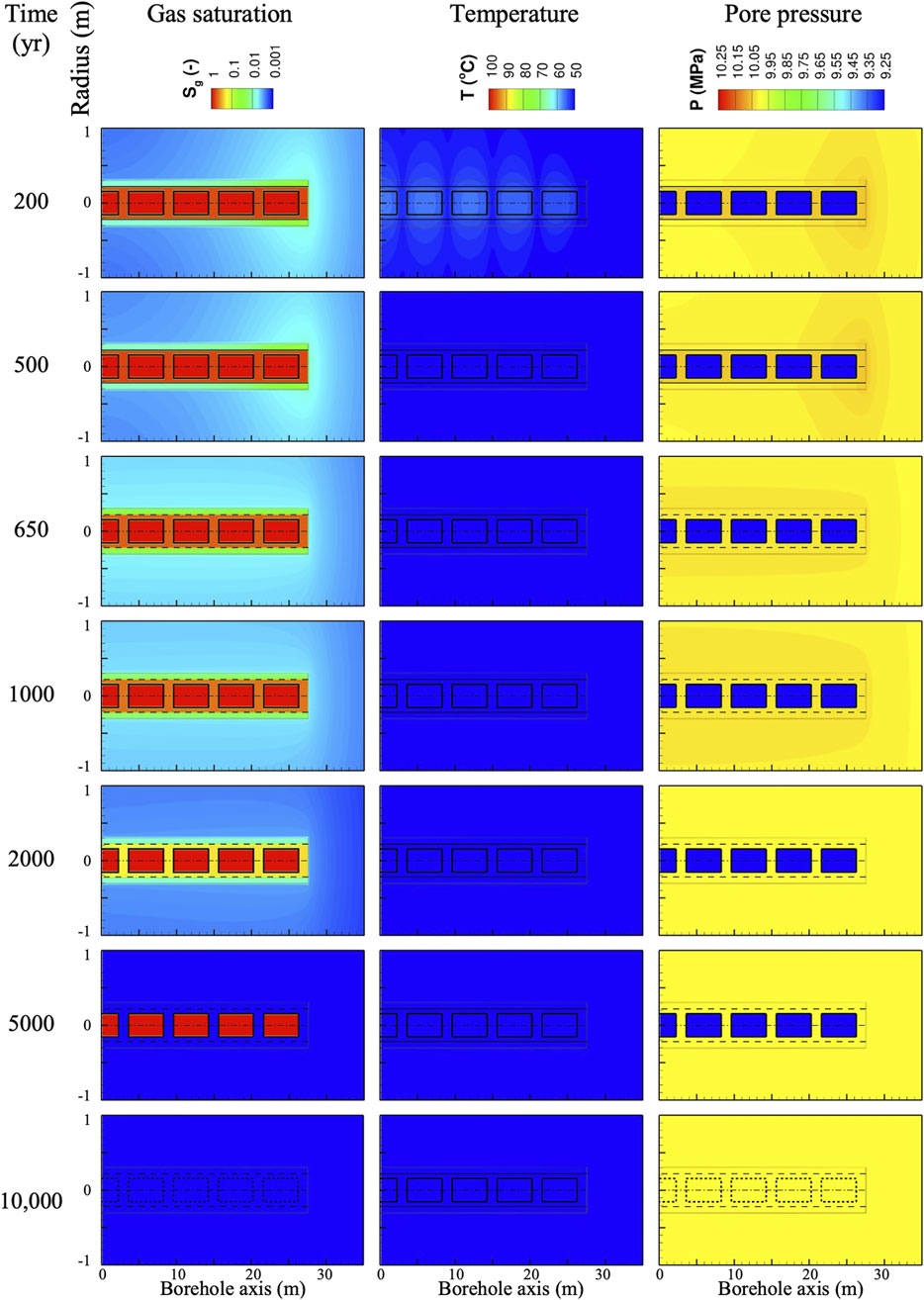
Figure 4. Evolution of gas saturation, temperature, and pore pressure up to 10,000 years (radial direction is exaggerated by a factor of 10 to borehole axis).
After 8,926 years, the canister shell is breached, and the inert gas within the void space at low pressure is relatively quickly compressed and dissolved as the canister is flooded. Corrosion of the canister—including the bottom plate, top lid, and lifter adapter—continues until they are fully consumed (see Table 3). Recall that after canister breach, the gas generation rate is doubled due to the corrosion of the canister from the inside after water entry. Nevertheless, the gas is dissolved in the liquid and continually removed by outward diffusive transport, preventing the emergence of a free gas phase, thus no longer affecting the hydraulic state of the system.
As gas is generated in different compartments, and the barriers separating these compartments are breached by corrosion at different times, gas accumulation and dissipation changes abruptly depending on the corrosion of the casing and canisters, as illustrated in Figure 5. As long as the casing is intact, the hydrogen generated from the canisters and the inner surface of the casing is essentially trapped in the space within the casing. The hydrogen generated from the outer surface and the gas flowing around the end of the casing back into the cement-filled annulus is considerably smaller, and only a small portion thereof leads to a free gas phase in the drilling-disturbed zone (Figure 5A). After the casing is breached, the gas escapes, reducing the average gas saturation between the canisters and the casing, but increasing the saturation in the cement from where it dissipates into the surrounding host formation. Once the casing is consumed, the hydrogen generation rate drops considerably (note that hydrogen generation from the corroding inner and outer surface areas of the casing are about 44 times higher than the rate from a canister; see Table 3). Consequently, the gas saturation is reduced as gas advectively flows outwards while liquid water is pulled inwards by capillary forces. The decline in saturation slows down once the pressure buildup within the casing has dissipated after about 1,500 years. The gas generation rate from the canisters alone is small so that after about 3,000 years, all of the hydrogen dissolves in the liquid phase and migrates radially outwards into the formation (Figure 5B). Once the shell is breached, the canister also corrodes from the inside, temporarily increasing the hydrogen generation rate until the shell is fully consumed. Small amounts of hydrogen continue being generated by the corrosion of the end plates and lift adapter, until all iron components are oxidized after about 70,000 years.
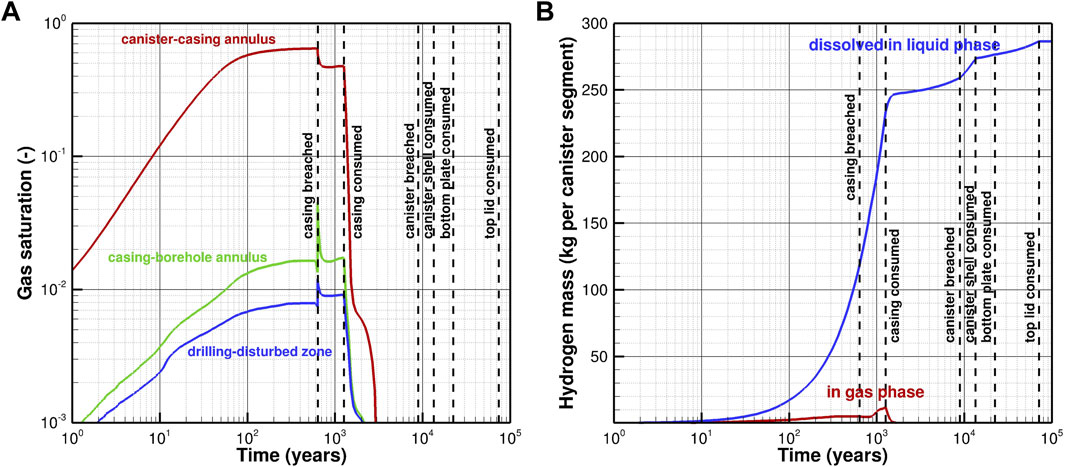
Figure 5. Evolution of (A) average gas saturation in different compartments, and (B) total mass of hydrogen present in the gas and liquid phase.
3.1.3 Impact of water consumption
The evolution of average gas saturation in the confined EBS is also affected by water being consumed by the corrosion reaction. To examine this effect, a sink term is introduced whereby 1 mol of H2O is removed for each mole of H2 being generated. As the water contained in the annulus between the canister and casing is limited, its consumption tends to increase the gas saturation to the point where relative humidity, water contact area with the metal surface, and water availability for the reaction decline, reducing corrosion, gas generation, and consequently also water consumption rates. The current thermal-hydrological model does not mechanistically represent these processes; instead, the simple approximation of Croisé et al. (2011) is used, in which the gas generation rate (and corresponding water consumption rate) is linearly reduced as a function of local liquid saturation, with corrosion stopping altogether if liquid saturation is below 10%.
Figure 6 shows the impact of water consumption and saturation-dependent reduction in corrosion rate on average saturations and hydrogen accumulation for the first 300 years after waste emplacement. Despite the reduced corrosion rate, the gas saturation in the canister-casing annulus is higher as a result of water consumption. Corrosion stops altogether once the gas saturation reaches 90%. Nevertheless, the casing will eventually be breached as corrosion of its outer surface continues, with water supplied from the host rock. Figure 6B confirms that the total amount of hydrogen being generated in the first 300 years is slightly reduced due to the saturation-dependent reduction in corrosion rate, and that a larger amount of hydrogen is present in the gas phase near the corroding surfaces, with correspondingly less hydrogen dissolved in the liquid phase, which also reflects the reduced fluid pressure caused by water consumption. As the density of the corrosion product is lower compared to the steel, the volume increases and correspondingly the porosity is reduced; this effect is not accounted for in these simulations. However, the overall effect is minor, except for the delay of the casing breach time. For the remaining simulations using the repository-scale model, we ignore water consumption and saturation-dependent corrosion-rate reduction and assume that gas generation proceeds at the higher, initial rate until the metal components in the EBS are fully consumed.
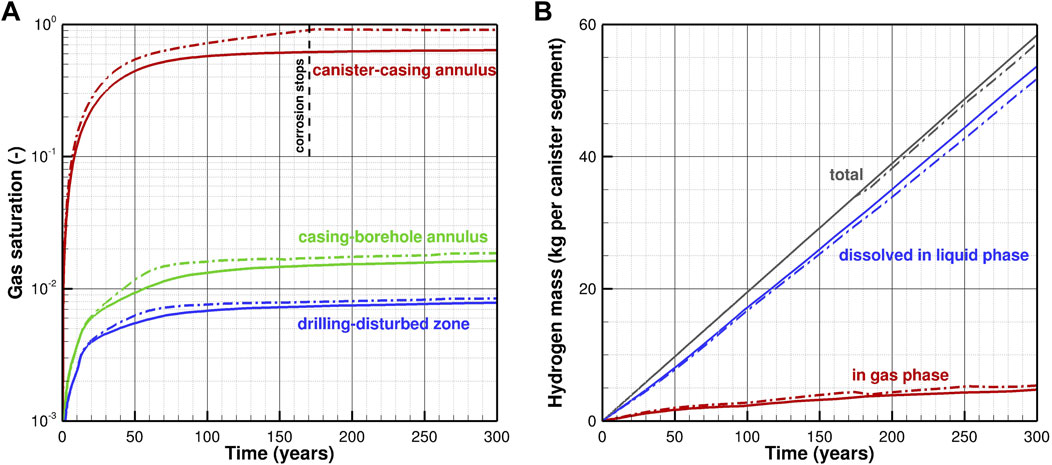
Figure 6. Evolution of (A) average gas saturation in different compartments, and (B) total mass of hydrogen present in the gas and liquid phase, with (dash-dotted lines) and without (solid lines) accounting for water consumption and saturation-dependent reduction in corrosion rate.
3.2 Repository-scale model
3.2.1 System evolution for reference scenario
While the canister-scale model shows the general gas flow behavior within the EBS components, the representation of only a short string of canisters and their proximity to the end of the borehole do not realistically capture the conditions in a long disposal section. In particular, gas generated from canisters that are emplaced far from the escape point at the end of the casing must travel a long distance while the casing remains intact. This long travel distance and the accumulation of gas generated by all the canisters along the flow path will likely lead to the development of higher pressures within the canister-casing annulus. Similarly, the temperatures near the center of the disposal section are expected to be higher than shown in the previous section, even though heat (unlike gas) readily dissipates by conduction through the hydraulically impermeable casing.
We focus here on only one performance metric of the entire repository system, which is the maximum overpressure generated by thermal effects and gas generation. The temperature distribution is quite uniform along the disposal section, except for the first and last 80 m of the disposal section, which are slightly cooler because of end effects. As the disposal section is inclined upwards by 3° (see Figure 1), there is a mild temperature decrease between the beginning and the end of the borehole, reflecting the geothermal gradient. The maximum temperature of a long string of heat-generating radioactive waste (Figure 7A) is considerably higher if heat dissipation is essentially cylindrical compared to the more prolate spheroid shape of the temperature contours around the short disposal section presented in the previous section. (A typical repository-scale temperature distribution is shown in Figure 5 of Finsterle et al. (2020)). Peak temperatures are encountered approximately 10 years after waste emplacement, declining rapidly thereafter due to the reduction in the decay heat of 137Cs and 90Sr, which are the dominant heat-releasing fission products in the waste form (Forsberg, 2000). It is important to realize that despite the temperatures exceeding 270 °C, the high pressures at the repository depth prevent the fluid in contact with the canister surface from boiling. Unlike in mined repositories, which rely on the swelling and retention capacity of a clay-based buffer material that could deteriorate if exposed to steam or elevated temperatures, such high temperatures are considered acceptable in a borehole repository. In the absence of boiling, the gas phase in the borehole mainly consists of hydrogen from the corrosion of the canisters and casing, with water vapor being the secondary component.
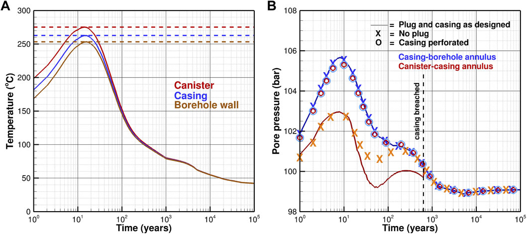
Figure 7. Evolution of (A) maximum temperature, and (B) maximum gas pressure along the horizontal waste disposal section of a horizontal borehole repository.
Figure 7B shows the pressure evolution. For the reference case (where the plug and casing effectively prevent fluids from escaping into the access hole and near field, respectively), the pressure maximum in the inner annulus is located about 110 m from the beginning of the disposal section. The obvious correlation of the initial pressure rise to the temperature evolution of Figure 7A indicates that thermal expansion of the fluid enclosed within the casing and also within the pores of the tight host rock is the dominant driver of pressure changes. Due to the high axial permeability of the open space between the canisters and the casing, the pressure buildup in the inner annulus can dissipate and is thus lower than the one caused by thermal expansion of the liquid in the tight pore space of the host rock.
In the reference case (solid lines), which assumes that the casing remains impermeable up to the breach time of 632 years, the continuous generation of hydrogen gas leads to a secondary pressure maximum within the canister-casing annulus, reaching its peak value after approximately 250 years (red solid line). At the time the casing is breached, the pressures quickly equilibrate with the near-field pressure, and then decline in response to continuous gas dissipation and cooling, as discussed in more detail in Section 3.1 above.
3.2.2 Impact of borehole sealing on gas pressure buildup
Assuming that there is no plug placed between the vertical access hole and the horizontal disposal section of the borehole, fluid expanding during the early-time heat-up period is pushed upwards into the access hole. However, as soon the temperatures start declining, the water flows back into the canister-casing annulus and keeps it pressurized (orange crosses), whereas in the reference case, the fluid contraction is not readily compensated, leading to a pressure minimum after about 50 years, which is followed by repressurization due to the continued generation of corrosion gases. Note that the pressure evolution outside the casing (blue crosses) is not influenced by the performance of the plug.
3.2.3 Impact of casing integrity on gas pressure buildup
As a final sensitivity case, we study the situation in which the casing is either intentionally perforated or breached at an early time. The details of the perforation are not expected to be relevant, as long as the perforation leads to an effective permeability of the casing that is equal or larger than that of the host rock. The absence of the casing’s hydraulic barrier leads to a pressure equilibration within the borehole, which is controlled by the near-field conditions, as indicated by the overlapping circles and their proximity to the blue line of the reference case.
3.2.4 Gas flow and liquid displacement
Thermal fluid expansion and the emergence of a free gas phase not only increases pore pressures (which could affect the barrier functions of the engineered components and the near-field geosphere), but also expels gas and liquid that potentially carry radionuclides from the disposal section into the access hole or host rock. While no simulations of the release of radionuclides from the canisters and their subsequent migration through the engineered and natural barrier systems are performed here, Figure 8 shows the volumetric rate of gas and liquid entering the host rock, as well as the amount of liquid being pushed into the vertical access hole. For the reference case with an intact plug and casing (solid lines), only a small amount of liquid migrates through the low-permeable plug, whereas the thermal expansion and the gas being generated by the corrosion of the outer casing surface pushes the pore water and gas from the cement and DDZ into the host rock.
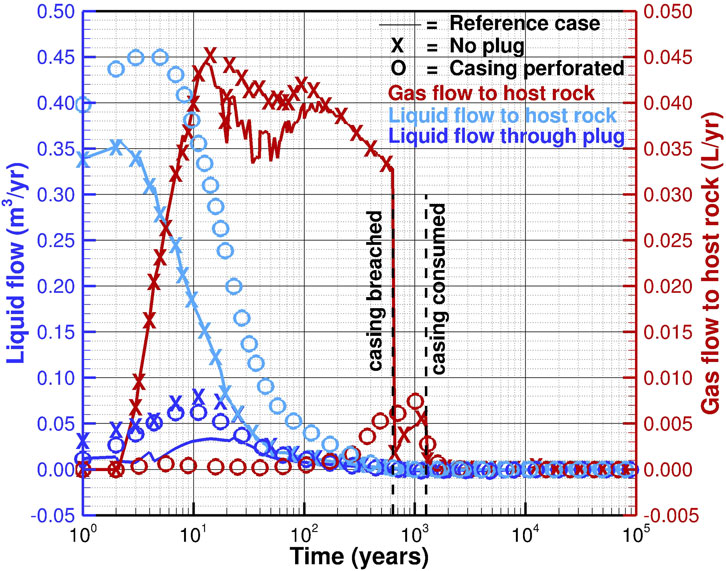
Figure 8. Total volumetric flow rates of liquid (blue) and gas (red) into the host rock and vertical access hole.
As gas saturations in the two annuli increase, the liquid relative permeability drops. At the same time, capillary retention becomes stronger in the outer annulus, and the total fluid compressibility in both compartments increases, allowing for additional gas to be accommodated without drastically raising the pressures. As a result, the liquid rates decline relatively fast.
Liquid movement is limited to the first 100 years after waste emplacement and becomes slightly negative (indicating convergent flow towards the canisters) afterwards due to thermal contraction. As soon as the casing is breached, gas flow to the host rock stops until the pressures between the two annuli equilibrate, before it resumes at a low rate in response to the continued corrosion of the casing until it is consumed. As discussed in the previous section, the hydrogen generated by the slow corrosion of the canisters is readily dissolved in the liquid phase and dissipates diffusively into the near field without additional advective transport in a free gas phase.
If the plug is leaking (crosses), the amount of liquid being pushed upwards into the access hole is more than doubled but does not affect the liquid flow into the host rock, which is compartmentalized by the intact casing. The increase of gas flow into the host rock results from the gas that is generated by corrosion of the vertical casing being pushed into the formation by the liquid now entering the access hole.
If the casing is assumed perforated or otherwise breached immediately after waste emplacement (circles), the liquid initially present in the open space between the canister and the casing is directly displaced into the host rock. This radial liquid release leads to slightly smaller axial flow and less water penetrating the plug. Gas generated by casing corrosion now preferentially enters the open space between the canisters and the casing rather than overcoming the gas entry pressures at the interfaces between the open space and the cement as well as the cement and the host rock. The onset of gas migration into the host rock is therefore delayed.
4 Concluding remarks
4.1 Summary
Hydrogen gas is generated mainly by the corrosion steel components in a repository of high-level radioactive waste and spent nuclear fuel. The appearance of a free gas phase may lead to overpressures that—combined with thermal stresses—could compromise the integrity of the engineered barriers and near-field host rock. Moreover, fluids displaced by the advancing gas front may contain dissolved or volatile radionuclides.
While these aspects have been extensively studied for mined repositories, we performed thermal-hydrological simulations of two-phase flow processes for a deep horizontal borehole repository with its distinct geometrical configuration of canisters, casing, and related annuli within a small-diameter deposition borehole. The model accounts for time-dependent hydrogen generation from various metallic surfaces, the breaching of the casing and canisters, the consumption of the engineered component and thus ending of gas generation, and—as a sensitivity analysis—the consumption of water as part of the corrosion reaction and the saturation-dependence of the corrosion rate.
Flow of water and hydrogen in both the liquid and gas phases were then simulated along with decay-heat release and its dissipation. A detailed model of a short disposal section was followed by a repository-scale simulation that focuses on the composite effects of gas and heat generation along a 1,000 m long disposal section. The impacts of the plug and a perforated casing were also evaluated. The system evolution was simulated up to 100,000 years, capturing the early-time, transient effects associated with the thermal period and higher gas generation, effects of breaching and consumption of the casing and canisters, and the equilibration to ambient conditions.
4.2 Main results
In general, the modeling revealed that the evolution of temperatures, pressures, and gas saturations are locally confined, occur over different temporal scales, and are marked by discrete events such as the breaching and consumption of the casing and canisters. The open space between the canisters and the casing, which is initially completely filled with a drilling or emplacement fluid, is confined by the impermeable casing, limiting fluid flow to occur in an axial direction towards the end of the casing, where gas and liquid backflow along the cemented outer annulus, and to a lesser extent towards the low-permeability plug, which restricts, but does not prevent, some fluid losses into the vertical access hole. Unlike gas, heat readily dissipates radially into the near field geosphere. This geometrical configuration is drastically changed once the casing is breached, allowing for pressure equilibration between the inner and outer annuli, and enabling fluid flow in both radial and axial directions.
At a much later time, the canisters are also breached. As they are filled with an inert gas at comparatively low pressure, they act as a sink until all the gas is compressed, dissolved, or released from the canister. At that time, corrosion of the inside canister wall begins, essentially doubling the gas generation rate. However, these rates are sufficiently small to allow the generated hydrogen to be dissolved in the liquid phase, where it diffuses radially away into the near field without forming a free gas phase.
The generated gas volumes are relatively small, partly because of the high-pressure environment prevailing in a deep horizontal borehole repository, which is near hydrostatic conditions both during and after waste emplacement. These high pressures enable larger amounts of hydrogen to be dissolved in the liquid phase. Once a free gas phase evolves, its density is relatively high, reducing the liquid volume being displaced and the resulting overpressurization of the system.
In fact, most of the pore pressure increases are due to the thermal expansion of the fluids rather than gas generation. These thermal effects are at their maximum just a few years after repository closure, and typically become insignificant after a few thousand years. This means that fluid displacements driven by both thermal effects and gas generation occur at very early times when it can be reasonably assumed that the canisters are intact and no radionuclides have been released; consequently, no accelerated transport of radionuclides along the borehole’s annuli or into the geosphere will occur as a result of gas generation. The simulations also show that the fluid volumes migrating due to repository-induced effects are very small, and no gas generated within the disposal section will ascend the access hole, even in the absence or failure of the plug. (The gas present in the access hole originates only from the corrosion of the vertical casing and is therefore uncontaminated). The repository configuration with a 3° upwards inclination of the disposal section away from the access hole further ensures that volatile radionuclides potentially released from an early canister failure are unlikely to escape through the access hole but would flow along the predominant, axial pressure gradient and buoyancy towards the dead-end of the disposal section.
Finally, it is noticed that the casing plays a crucial role in the behavior of corrosion gases within a borehole repository. First, the carbon-steel casing is a major source of hydrogen, which is generated much faster due to a considerably larger surface area and higher corrosion rate than the gas released from the corrosion of the duplex steel canisters. In addition, the intact casing releases the gases generated at each of its surfaces to separate compartments, leading to gas accumulation within the inner annulus and dehydration of the cement in the outer annulus with the associated sudden reconfiguration of the system once the casing is breached. Nevertheless, the simulations suggest that these issues do not seem to have a detrimental effect on the overall system performance. The main roles of the casing are to ensure borehole stability and to facilitate emplacement and potential retrieval of the canisters prior to repository closure. As no safety-relevant barrier function is associated with the casing, its perforation for pressure release is not only acceptable, but may even be preferable assuming that this does not affect the casing’s pre-closure performance.
4.3 Conclusion
The following conclusions are drawn:
• Gas generation from the corrosion of the canister and casing in a deep horizontal borehole repository is unlikely to lead to safety concerns related to either the integrity of the engineered barrier system or the accelerated transport of volatile or dissolved radionuclides.
• Gas effects are dominated by the corrosion of the casing and are therefore limited to a relatively short period after repository closure.
• Related pressure effects are secondary to those induced by the thermal expansion and contraction of the fluids.
• Design details of the repository components, such as the presence or performance of the plug, and the integrity of the casing, appear to have a minor impact.
• The robustness of the system to repository-induced effects from heat and gas generation is believed to be inherent in the borehole repository concept itself. In particular, the large depth combined with fully liquid-saturated conditions throughout the emplacement, closure, and disposal phases ensure reducing conditions and relatively low corrosion rates. More importantly, these conditions lead to high pore pressures which (a) prevent boiling and steam generation, (b) enhance hydrogen dissolution in the liquid phase, (c) increase gas-phase density, and (d) provide room for gas accumulation in the open space between the canisters and the casing; all these factors reduce fluid displacement volumes, pressure build-up, and the migration of radionuclides.
Given the limited, short-term impact gas generation has on the state of the borehole and its immediate near field, no long-term radiological consequences are expected, i.e., the preliminary conclusions regarding peak dose exposure drawn from generic performance assessment models for borehole repositories still apply.
Data availability statement
The original contributions presented in the study are included in the article/supplementary material, further inquiries can be directed to the corresponding author.
Author contributions
SF: Conceptualization, Data curation, Formal Analysis, Methodology, Software, Validation, Visualization, Writing – original draft. MW: Conceptualization, Data curation, Formal Analysis, Funding acquisition, Project administration, Supervision, Writing – original draft. MY: Conceptualization, Data curation, Formal Analysis, Writing – review and editing. KT: Conceptualization, Data curation, Supervision, Writing – review and editing.
Funding
The author(s) declare that financial support was received for the research and/or publication of this article. This work was supported by the UK Energy Entrepreneurs Fund. The work was overseen by the UK Department for Energy Security and Net Zero. Their support enabled this collaboration between Finsterle GeoConsulting, Deep Isolation, and the University of Sheffield.
Acknowledgements
We thank the technical reviewer for the detailed and constructive comments.
Conflict of interest
Author SF was employed by Finsterle GeoConsulting, LLC. Author MW was employed by Deep Isolation Nuclear, Inc.
The remaining authors declare that the research was conducted in the absence of any commercial or financial relationships that could be construed as a potential conflict of interest.
Generative AI statement
The author(s) declare that no Generative AI was used in the creation of this manuscript.
Any alternative text (alt text) provided alongside figures in this article has been generated by Frontiers with the support of artificial intelligence and reasonable efforts have been made to ensure accuracy, including review by the authors wherever possible. If you identify any issues, please contact us.
Publisher’s note
All claims expressed in this article are solely those of the authors and do not necessarily represent those of their affiliated organizations, or those of the publisher, the editors and the reviewers. Any product that may be evaluated in this article, or claim that may be made by its manufacturer, is not guaranteed or endorsed by the publisher.
References
Avis, J., Suckling, P., Calder, N., Walsh, R., Humphreys, P., and King, F. (2014). T2GGM: a coupled gas generation model for deep geologic disposal of radioactive waste. Nucl. Technol. 187, 175–187. doi:10.13182/NT13-83
Brady, P. V., Arnold, B. W., Freeze, G. A., Swift, P. N., Bauer, S. J., Kanney, J. L., et al. (2009). Deep borehole disposal of high-level radioactive waste. Report SAND2009-4401. Albuquerque, NM, USA: Sandia National Laboratories, 75.
Croisé, J., Mayer, G., Marschall, P., Matray, J.-M., Tanaka, T., and Vogel, P. (2006). “Gas threshold pressure test performed at the mont Terri Rock Laboratory (Switzerland): experimental data and data analysis,” Oil & Gas Science and Technology - Revue d’IFP Energies nouvelles, 61 (5), 631–645. Institut Français du Pétrol, Rueil-Malmaison, France. doi:10.2516/ogst:2006003
Croisé, J., Mayer, G., Talandier, J., and Wendling, J. (2011). Impact of water consumption and saturation-dependent corrosion rate on hydrogen generation and migration from an intermediate-level radioactive waste repository. Transp. Porous Media 90, 59–75. doi:10.1007/s11242-011-9803-0
Diomidis, N., Cloet, V., Leupin, O. X., Marschall, P., Poller, A., and Stein, M. (2016). Production, consumption and transport of gases in deep geological repositories according to the Swiss disposal concept. Wettingen, Switzerland: Nagra.
Faybishenko, B., Wang, Y., Harrington, J., Tamayo-Mas, E., Birkholzer, J., and Jové-Colón, C. (2022). Phenomenological model of nonlinear dynamics and deterministic chaotic gas migration in bentonite: experimental evidence and diagnostic parameters. Trans. Porous Med. 141, 585–606. doi:10.1007/s11242-021-01733-9
Finsterle, S., Commer, M., Edmiston, J., Jung, Y., Kowalsky, M. B., Pau, G. S. H., et al. (2017). iTOUGH2: a multiphysics simulation-optimization framework for analyzing subsurface systems. Comput. and Geosciences 108, 8–20. doi:10.1016/j.cageo.2016.09.005
Finsterle, S., Muller, R. A., Baltzer, R., Payer, J., and Rector, J. W. (2019). Thermal evolution near heat-generating nuclear waste canisters disposed in horizontal drillholes. Energies 12 (4), 596. doi:10.3390/en12040596
Finsterle, S., Muller, R. A., Grimsich, J., Apps, J., and Baltzer, R. (2020). Post-closure safety calculations for the disposal of spent nuclear fuel in a generic horizontal drillhole repository. Energies 13, 2599. doi:10.3390/en13102599
Finsterle, S., Cooper, C., Muller, R. A., Grimsich, J., and Apps, J. (2021a). Sealing of a deep horizontal borehole repository for nuclear waste. Energies 14 (1), 91. doi:10.3390/en14010091
Finsterle, S., Muller, R. A., Grimsich, J., Bates, E. A., and Midgley, J. (2021b). Post-closure safety analysis of nuclear waste disposal in deep vertical boreholes. Energies 14 (19), 6356. doi:10.3390/en14196356
Finsterle, S., Llabjani, Q., Ferrari, A., and Marschall, P. (2025). Two-phase analysis of oedometric gas injection tests with simplified representation of geomechanical effects. Comput. Geosci. 29, 39. doi:10.1007/s10596-025-10379-1
Forsberg, C. W. (2000). Rethinking high-level waste disposal: separate disposal of high-heat radionuclides (90Sr and 137Cs). Nucl. Technol. 131, 252–268. doi:10.13182/NT00-A3115
Gibb, F. G. F., Travis, K. P., McTaggart, N. A., and Burley, D. (2008). A model for heat flow in deep borehole disposals of high-level nuclear waste. J. Geophys. Res. 113, B05201. doi:10.1029/2007JB005081
Grundfelt, B., and Crawford, J. (2014). The deep borehole concept—A conceptual model for gas generation and gas transport. Stockholm, Sweden: Svensk Kärnbränslehantering AB SKB.
IAPWS (2007). International Association for the properties of water and steam: revised release on the IAPWS industrial formulation 1997 for the thermodynamic properties of water and steam. Switzerland: IAPWS Release.
Jacops, E., Volckaert, G., Maes, N., Charlier, R., Collin, F., Gerard, P., et al. (2014). WP5 Final report: experiments and modelling of gas migration processes in undisturbed rocks. FORGE Rep. D5. 19, 146.
Khalaf, A. H., Lin, B., Bo, Z., Xiao, Y., Abdalla, A. N., and Tang, J. (2025). Corrosion rate prediction and inhibitor optimization for L80-1 steel and alloyed materials using response surface methodology. Surf. Sci. Technol. 3 (25), 25. doi:10.1007/s44251-025-00086-5
King, F., Kolàr, M., Briggs, S., Behazin, M., Keech, P., and Diomidis, N. (2024a). Review of the modelling of corrosion processes and lifetime prediction for HLW/SF containers—Part 1: process models. Corros. Mater. Degrad. 5 (2), 124–199. doi:10.3390/cmd5020007
King, F., Kolàr, M., Briggs, S., Behazin, M., Keech, P., and Diomidis, N. (2024b). Review of the modelling of corrosion processes and lifetime prediction for HLW/SF containers—Part 2: performance assessment models. Corros. Mater. Degrad. 5 (2), 289–339. doi:10.3390/cmd5020013
Luckner, L., van Genuchten, M.Th., and Nielsen, D. (1989). A consistent set of parametric models for the two-phase flow of immiscible fluids in the subsurface. Water Resour. Res. 25 (10), 2187–2193. doi:10.1029/WR025i010p02187
Marschall, P., Horseman, S., and Gimmi, T. (2005). Characterisation of gas transport properties of the Opalinus Clay, a potential host rock formation for radioactive waste disposal. Oil and Gas Sci. Technol. 60 (1), 121–139. doi:10.2516/ogst:2005008
Muller, R. A., Finsterle, S., Grimsich, J., Baltzer, R., Muller, E. A., Rector, J. W., et al. (2019). Disposal of high-level nuclear waste in deep horizontal drillholes. Energies 12, 2052. doi:10.3390/en12112052
Nagra (1994). Report NTB 93-22. Kristallin-I—Safety assessment report. Wettingen: Nagra (National Cooperative for the Disposal of Radioactive Waste).
Nagra (2004a). Report NTB 08-06: Effects of post-disposal gas generation in a repository for spent fuel, high-level waste and long-lived intermediate level waste sited in the opalinus clay. Wettingen: Nagra (National Cooperative for the Disposal of Radioactive Waste).
Nagra (2004b). Report NTB 08-07: Effects of post-disposal gas generation in a repository for low- and intermediate-level waste sited in the opalinus clay of Northern Switzerland. Wettingen: Nagra (National Cooperative for the Disposal of Radioactive Waste).
Nagra (2008). Report NTB 08-07: Effects of post-disposal gas generation in a repository for Low- and intermediate-level waste sited in the opalinus clay of Northern Switzerland. Wettingen: Nagra (National Cooperative for the Disposal of Radioactive Waste).
Nagra (2016). Report NTB 16-05: An assessment of the possible fate of gas generated in a repository for low- and intermediate-level waste. Wettingen: Nagra (National Cooperative for the Disposal of Radioactive Waste).
Nirex (2004). A review of the deep borehole disposal concept for radioactive waste. Harwell, UK: United Kingdom Nirex Limited, 89.
NWMO (2018). Postclosure safety assessment of a used fuel repository in sedimentary rock. Report NWMO-TR-2018-08. Toronto, ON, Canada: Nuclear Waste Management Organization, 748.
Pruess, K., Oldenburg, C., and Moridis, G. (2012). TOUGH2 User’s Guide, Version 2.1. Berkeley, CA: Lawrence Berkeley National Laboratory.
Rodwell, W. R., Harris, A. W., Horseman, S. T., Lalieux, P., Müller, W., Ortiz Amaya, L., et al. (1999). Gas migration and two-phase flow through engineered and geological barriers for a deep repository for radioactive waste. Eur. Comm. Rep. 19122 En.
Senger, R., Xu, T., Marschall, P., and Finsterle, S. (2008). Investigation of two-phase flow phenomena associated with corrosion in an SF/HLW repository in Opalinus clay, Switzerland. Phys. Chem. Earth 33, S317–S326. doi:10.1016/j.pce.2008.10.034
Vargaftik, N. B. (1975). Tables on the thermophysical properties of liquids and gases. 2nd Ed. New York, NY: John Wiley and Sons.
Vehling, F., Kosakowski, G., and Shao, H. (2024). Two-phase reactive transport modeling of heterogeneous gas production in a low- and intermediate-level radioactive waste repository. App. Geochem. 178, 106219. doi:10.1016/j.apgeochem.2024.106219
Waples, M., Bates, E. A., Gingrich, S., and Griffith, A. (2025). “Accelerated high-temperature and pressure demonstration of deep borehole disposal canister technology,” in Waste Management Symposia 2025. Available online at: https://www.deepisolation.com/wp-content/uploads/2025/03/SAVANT-WMS25-Final-Paper-27-Jan.pdf (Accessed October 20, 2025).
Wieland, E., Kosakowski, G., Lothenbach, B., and Kulik, D. A. (2020). Geochemical modelling of the effect of waste degradation processes on the long-term performance of waste forms. Appl. Geochem. 115, 104539. doi:10.1016/j.apgeochem.2020.104539
Keywords: radioactive waste disposal, horizontal borehole repository, corrosion gas, performance assessment, two-phase flow, iTOUGH2
Citation: Finsterle S, Waples M, Yang M and Travis KP (2025) Generation and dissipation of corrosion gas in a deep horizontal borehole repository for radioactive waste. Front. Nucl. Eng. 4:1689795. doi: 10.3389/fnuen.2025.1689795
Received: 20 August 2025; Accepted: 24 October 2025;
Published: 20 November 2025.
Edited by:
Yuankai Yang, Forschungszentrum Juelich, GermanyReviewed by:
Vanessa Montoya, Helmholtz Association of German Research Centres (HZ), GermanyLuo Ying, Southwest University of Science and Technology, China
Copyright © 2025 Finsterle, Waples, Yang and Travis. This is an open-access article distributed under the terms of the Creative Commons Attribution License (CC BY). The use, distribution or reproduction in other forums is permitted, provided the original author(s) and the copyright owner(s) are credited and that the original publication in this journal is cited, in accordance with accepted academic practice. No use, distribution or reproduction is permitted which does not comply with these terms.
*Correspondence: Stefan Finsterle, c3RlZmFuQGZpbnN0ZXJsZS1nZW9jb25zdWx0aW5nLmNvbQ==