 Zhenkai Chen
 Wenjing Zhou
 Zhou Ge
 Yingjie Yu
 Hongbo Zhang2
 Ting-Chung Poon
- 1Department of Precision Mechanical Engineering, Shanghai University, Shanghai, China
- 2Department of Engineering Technology, Middle Tennessee State University, Murfreesboro, TN, United States
- 3Bradley Department of Electrical and Computer Engineering, Virgina Tech, Blacksburg, VA, United States
Digital holography enables quantitative phase imaging based on interference. A digital hologram often encodes the phase information along with aberrations or deformations. This article reviews phase analysis and its diverse application solutions and challenges in digital holography including aberrations removal in a single hologram, defect and deformation detection using dual-holograms, and defect location in multi-holograms. The state-of-the-art of the techniques are presented and discussed in detail for phase analysis, separation, and quantification. Phase analysis in digital holography can provide high precision, high resolution, rapid quantitative and intelligent imaging abilities.
1 Introduction
Holography was invented in 1948 by Dennis Gabor to improve the resolution of electron microscopes limited by spherical aberrations (Gabor, 1948). Off-axis illumination set-up with an off-axis reference beam was proposed by Leith and Upatnieks in 1964 (Leith and Upatnieks, 1964). Off-axis set-up eliminates the spectral overlap of the zeroth-order beam and the twin image inherent in Gabor’s in-line configuration. While electronic detection of holograms was first performed by Enloe et al., in 1966 (Enloe et al., 1966), digital reconstruction of holograms was constructed by Goodman and Lawrence in 1967. The technique of recording and reconstructing holograms using a CCD sensor and numerical methods has been documented by Schnars and Jueptner (Cuche et al., 1999; Schnars and Jüptner, 1994) and was known as digital holography (DH). Nowadays digital holography could also mean that hologram recording is done by an electronic device such as a CCD, CMOS sensor or a photodetector, and the recorded hologram can be numerically or optically reconstructed (Mann et al., 2005; Zhang and Poon, 2023). Using coherent mode (Mann et al., 2005), Digital Holography (DH) is capable of producing phase-contrast images without requiring labels. This distinctive attribute of the quantitative phase imaging technique is straightforward, non-invasive, and allows for dynamic imaging processes. At present, DH has been widely used in 3D profile detection (Nilsson, 2000; Ye et al., 2022; Dekiff et al., 2015; Shi et al., 2013; Andrés et al., 2020; Zhang, 2005), dual-wavelength recording (Kumar et al., 2009; Claus et al., 2021), microscopic observation (Chen et al., 2023a; Merola et al., 2013a; Merola et al., 2013b; Schnars and Jüptner, 2002), out-of-plane/in-plane deformation detection (Wang S. et al., 2018; Lee et al., 2012; Long et al., 2023; Li P. et al., 2018; Zhao et al., 2021; Sjödahl and Saldner, 1997; Saucedo et al., 2006; Schedin et al., 1999; Viotti et al., 1999; Li et al., 2021; Takatsuji et al., 1997; Nilsson et al., 1997; Arai, 2016), particle field analysis and testing (Tornari, 2014; Miccio et al., 2014; Ooms et al., 2008; Pan and Meng, 2003; Merola et al., 2016), bio-samples recognition (Mandracchia et al., 2019), stroboscopic vibration detection (Singh et al., 2007; Osten, 2019; Rembe and Muller, 2002; Hart et al., 2000; Lipiainen et al., 1997; Hansel et al., 2009) and other applications.
DH encodes the phase information along with the fringes as shown in Figures 1–3. A hologram, shown in Figure 1A, can be acquired by on-axis or off-axis recording, during static/dynamic acquisition, or single-wavelength/dual-wavelength interferometry. Phase reconstruction algorithm is used to obtain the wrapped phase by arctangent operation. However, the fringes due to aberrations also appear in the wrapped phase, compromising phase retrieval in terms of fringe patterns. In the subsequent unwrapping process, the fringes dominate in graphic representation masking the target information, leading to errors in phase reconstruction as shown in Figure 1B. The separation and compensation of the fringes is important for improving the accuracy of quantative phase imaing (Huang and Cao, 2023). Aberration can be effectively eliminated by physical or numerical methods. In the physical methods, practical solutions include introducing additional objectives in the optical path (Mann et al., 2005; Li et al., 2019), such as the use of a telecentric lens structure (Sánchez-Ortiga et al., 2011; Sánchez-Ortiga et al., 2014; Matkivsky et al., 2016), or the insertion of an electrically tunable lens in the illumination paths (Doblas et al., 2015; Deng et al., 2017a). Compared with physical approaches, numerical compensation methods are more flexible for phase compensation without any additional physical devices (Chen et al., 2023a; Liu S. et al., 2018; Schnars and Jüptner, 2002). It is accepted that the unwrapped phase consists of two parts: a) non-zero phase information located on a relatively flat base phase; b) polynomial-fitting surfaces with oblique or spherical features. Therefore, after removing the quadratic aberration of spherical features, the phase subtraction can obtain accurate sample phase information.

Figure 1. The process of obtaining the fringe patterns and target information based on a single hologram. (A) The process of obtaining the phase of a package from a single wavelength or dual wavelength hologram. (B) The process of eliminating quadratic term aberrations (Chen et al., 2023a; Schnars and Jüptner, 2002).
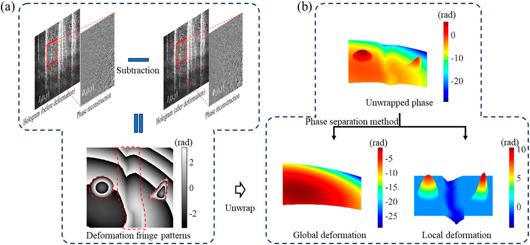
Figure 2. The process of obtaining the fringe patterns and local deformation based on dual-holograms. (A) The process of obtaining the phase of deformation by subtracting the phase before and after deformation, in which red dotted lines indicate the positions of defects. (B) The global and local deformations are obtained separately by the method of phase separation method (Schnars and Jüptner, 2002; Chen et al., 2024).
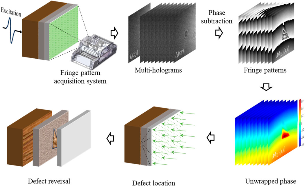
Figure 3. Multiple holograms utilize redundant information for dynamic monitoring: K-1 phase difference sequence obtained from K adjacent holograms. Inverting the deformation information into the surface of the object for defect location and reversal (Goursolle et al., 2007; Zhou et al., 2022; Chen S. et al., 2023).
As shown in Figure 2A, in dual-holograms, researchers typically apply additional deformations to the object, so that the axial deformation phase can be obtained by subtracting the same topography information. The above deformation phases often exceed the wavelength of the laser, resulting in discontinuity at 2π through the arctangent operation (Schnars and Jüptner, 2002; Chen et al., 2024; Chen et al., 2023c). The separated fringes are usually quadratic or higher-order polynomial-fitting surfaces that contain aberrations or deformation information. Similarly, the isolated target information may consist of profile or local regional deformation. As shown in Figure 2B, the surface of the object is deformed by external excitation, i.e., the unwrapped phase, which includes the global off-surface deformation of the surface and the local deformation caused by defects (or unevenness) of the object. By separating the global and local phases, they can be analyzed separately and specific defect quantification results can be obtained.
For multiple holograms as shown in Figure 3, the obtained phase difference sequence has a certain regularity. Under the conditions of deformation excitation such as acoustic, light or thermal energy, the fringe analysis in phase difference is of significance in the fields of calibration (Long et al., 2023), motion analysis (Fu et al., 2009), and high-speed inversion calculations (Trillo et al., 2010a). In particular, if the off-surface deformation information is transmitted backwards to the surface of the object, it is possible to locate and reverse the internal defects (Trillo et al., 2011; Goursolle et al., 2007; Zhou et al., 2022; Chen S. et al., 2023; Zhu et al., 2023).
In this review, numerical strategies for the separation and analysis of phase in digital holography are organized through relevant applications and the quantity of employed holograms. In the wrapped phase map that contains fringes, the target information and the fringes are independent of each other (Chen et al., 2023a; Huang and Cao, 2023; Schnars and Jüptner, 2002). For different applications, these two types of phase information behave differently, and therefore need specific treatments. In a single hologram, the axial information of the object is the phase, and the numerical strategy focuses on eliminating or compensating for aberrations. Phase information is redundant in two or more holograms, in which the fringes contain information about frequency domain error, deformation, or movement. As the number of holograms increases, the phase information changes from undersaturation to supersaturation. Therefore, different countermeasures are needed to separate, quantify, and reverse the phase information.
The review is organized in terms of the number of holograms used in the analysis. For a single hologram (obtained from on-axis/off-axis, static/dynamic or single/dual wavelengths), the review is focused on the development in fringes as well as aberration separation, elimination, and compensation. For dual- or multi-holograms, we analyze deformations produced by external excitations encoded by fringes. These regular deformations involve the detection of the physical properties of the substance (superficial, subsurface, and internal defects). The advantages and limitations of different methods are analyzed. The future direction with regard to phase analysis has also been discussed.
2 Phase compensation and defect reversal in digital hologram
2.1 Phase aberration elimination in single digital hologram
2.1.1 Phase aberration elimination with prior knowledge
For on-axis, off-axis, multi-wavelength, and speckle interferometric systems, the acquired hologram is essentially an interferogram. Laser is the typical light source for DH, and its coherent properties allow to create interferograms. For multi-wavelength techniques, two or more of different lasers are coupled into a single interferometric geometry (Sova et al., 2002).
The interference of the coherent beams is recorded by a CCD or a complementary metal–oxide–semiconductor (CMOS) camera. The hologram is then transferred to a computer for reconstruction. The intensity distribution of the interferogram recorded by the CCD can be written as
where
For phase reconstruction, we first reconstruct the complex field either by Fresnel diffraction or the use of angular spectrum method. The wrapped phase map is subsequently obtained by arctangent operation. We express the reconstructed unwrapped total phase
where UNWRAP[⋅] indicates the phase unwrapping operation.
Phase aberration removal is essential for accurate phase analysis. Numerous approaches have been developed to compensate for the presence of aberrations and imperfections of the optical systems in DH from a numerical analysis point of view. In the process of optical imaging, phase aberrations include spherical aberration, chromatic aberration, and astigmatism aberration. Among them, the inconsistency of the beam focus causes spherical aberrations. For multi-wavelength hologram recording systems, chromatic aberration occurs as multiple wavelengths share the same imaging plane. Astigmatism aberration is commonly caused by the different focal length of the tangential and sagittal rays. Based on the numerical analysis of the above three phase aberrations, it can be found that either the Zernike polynomial or the standard polynomial can be fitted accurately, and the fitting result is generally quadratic term aberrations.
Compensation function is important for aberration computation. For a Mach-Zehnder setup, as shown in Figure 4A, the specimen can be removed. Two microscopic objectives are used, with a difference in the distance between them and the CCD. Combined with the carrier angle in Figure 4B, the optical path information is thought to be able to obtain the inclination angle, eccentricity, and surface curvature of the quadratic aberrations. It starts from an object-free region of the phase image as the initial phase map, the curvature and spherical center of the quadratic phase are calculated by measuring the distance of the optical path components (Coppola et al., 2010; Colomb et al., 2006a; Min et al., 2017; Liu et al., 2013; Miccio et al., 2007; Wang et al., 2014; Zuo et al., 2013a), especially distances among CCDs, lenses and objects. The phase compensation function can be modelled as
where
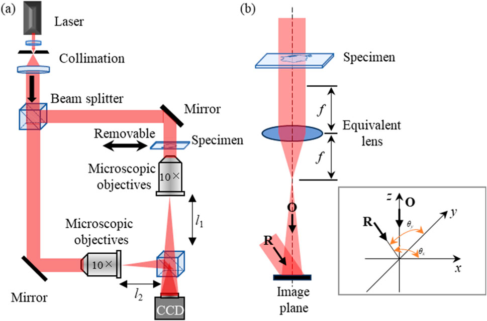
Figure 4. Schematic of the experimental setup for off-axis DH. (A) Typical Mach-Zehnder off-axis optical path; (B) Off-axis system and carrier angles.
However, the use of the above compensation function as Equation 3 depends on the availability of the optical path information and thus complicated to use in practice. Processing of the zeroth and first order spectra in DH is also important for the control of phase aberration. These two orders are obtained using the Fourier transform of the hologram. In off-axis holography, the reference beam interferes with the object beam at a certain angle, thus the positive and negative first-order spectrum will be separated from the zeroth-order spectrum at a certain angle and distance. Min et al. presented a simple and fast phase aberration compensation method in digital holographic microscopy for quantitative phase imaging of living cells (Min et al., 2017). Through the work, phase aberration compensation was then performed with the frequency spectrum of an off-axis hologram. Following the conversion of a hologram using Fourier transform as shown in Figure 5, critical parameters such as fringes are obtained. Consequently, aberrations are modelled as follows:
where A represents the effective magnification of the optical imaging system.
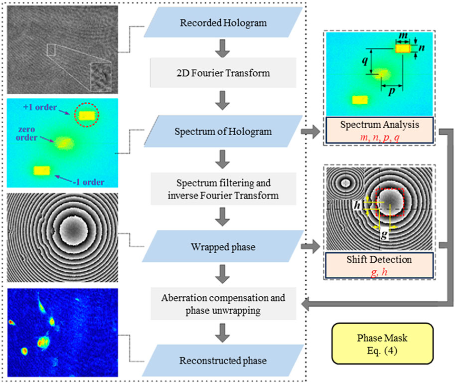
Figure 5. The process for aberration elimination based on spectrogram and fringe map measurement. [Reprinted/Adapted] with permission from ref (Min et al., 2017) © The Optical Society.
Alternating Direction Method (ADM) is also used to eliminate the global aberrations. A simple yet effective method is through the rotation of the hologram. For this, Deng et al. rotated the hologram by 180° by matrix rotation to eliminate oblique fringes, which is the primary aberration term, before aberration phase removal (Deng et al., 2017b). The above method is useful for eliminating the tilt aberration. Huang et al. presented an effective phase aberration-free synthetic-aperture phase microscopy by using the synthetic aperture (Huang et al., 2023). The synthetic aperture enables the rotation of the spectrogram, which can be solved by sparsity regularization technique for aberrations of each sub-aperture removal, resulting in a distortion-free high-resolution composite image. Based on structured illumination, Li et al. proposed a phase-shifting-free method to achieve an orthogonal polarization in the spectrum to improve the intensity and phase resolution of digital holography (Li S. et al., 2018).
Inspired by the connection between digital holography and transport-of-intensity, Zuo et al. proposed a numerical method for direct recovery of continuous phase information encoded in digital holography without phase (2π) discontinuities (Zuo et al., 2013b). The method is able to overcome the phase discontinuity problems in the phase unwrapping process, and at the same time automatically removes the tilt phase aberration. The technique is also capable of suppressing the quadratic aberration.
2.1.2 Phase aberration elimination without prior knowledge
Depending on the applications, phase aberrations are introduced by factors such as imperfect optical path set-up (Mann et al., 2005), numerical reconstruction (Zuo et al., 2013b; Wang et al., 2019), conjugate subtraction (Claus et al., 2021), and excitation conditions (Long et al., 2023; dePolo et al., 2021; Kosma et al., 2018; Tornari et al., 2020; Rippa et al., 2021). When obtaining a wrapped phase map with fringes and considering the loss of optical path information and the universality of the aberration elimination method, a direct aberration elimination method that does not require prior knowledge is recommended. Lateral sheer, spectral analysis and least-squares algorithms are commonly used for aberration elimination that require no prior knowledge (Ferraro et al., 2006; Liu et al., 2014; Di et al., 2009). Coppola et al. used the self-referencing method to process the unwrapped phase and eliminated the spherical aberration (Coppola et al., 2010). Through the use of spectral energy technique, Liu et al. derived a formula to automatically eliminate spherical aberrations (Liu et al., 2014).
Among these techniques, Zernike circular polynomials or normal polynomials (Liu et al., 2020) are often used to fit the surface of phase aberration produced by the coherent beams, allowing the characterization of the aberration of the geometrical wavefront.
Under such assumptions, there are two expressions for aberration
where
For Equations 5, 6, the solution of polynomial coefficients generally forms an overdetermined system (Di et al., 2009), which is obtained by the inverse operation of the matrix (Chen et al., 2023a; Schnars and Jüptner, 2002). The least-squares algorithm is a common surface fitting algorithm. However, overfitting is often introduced through the traditional least-squares algorithm. Miccio et al. discussed the relative relationship between the object phase and aberration in thin objects (Miccio et al., 2007). Overfitting can be overcome through the constrained matrix inversion and Zernike polynomials to obtain the quadratic aberration coefficients using
Coefficient optimization methods such as deep learning and weighted least-squares can also be applied to overcome overfitting problem (Schnars and Jüptner, 2002; Nguyen et al., 2017; Guo, 2011; Espinosa et al., 2011; Nam and Rubinstein, 2005). It is known that overfitting is attributed to the factors including position, shape, area and height of the sample phase (Liu Y. et al., 2018; Otsu). Liu et al. used the least squares algorithm and the background partition method to obtain more accurate polynomial fitting coefficients to alleviate overfitting (Liu et al., 2019). Within this method, the polynomial coefficients are obtained in an optimization procedure by minimizing the total standard deviation, i.e., the sum of local standard deviation of the compensated phase map. Since the phase variations from full-field (global) and selected area (local) are both considered, the proposed method is more accurate and robust than the state-of-the-art numerical methods (Liu et al., 2020).
Other phase aberration removal techniques inspired by the observation that the target phase is generally located on a relatively flat phase are also successful. As shown in Figure 6, the horizontal axis represents the complexity of the profile, and the vertical axis represents the area occupied by the sample phase. A common object is usually placed on a flat platform, and a numerical analysis of the phase using a histogram can reveal several distinct peaks in the histogram. These peaks tend to be distributed around the mean and standard deviation in their Gaussian distribution. Therefore, histogram and Gaussian distributions (HGD) plots of phase map are used to illustrate the difference between complex and large-area-ratio profile (Chen et al., 2023a; Schnars and Jüptner, 2002) in Figure 6. There are three typical target phase distributions as shown in Figures 6A, C, D: the stepped phase with a large area of phase difference (Chen et al., 2023a), biological cell samples with simple profile and small area ratios of the sample phase versus the total area of image (Liu et al., 2019), and the USAF resolution plate with a complex profile distribution (Schnars and Jüptner, 2002). Cells and USAFs in Figures 6C, D are common samples in phase aberration elimination, which dominate a small area ratio (the sample phase versus the total area of image generally less than 40%). For a phase with an area ratio of more than 50% such as illustrated in Figure 6A, the polynomial coefficients obtained from each side of the flat phase mixed with the aberration are not representative of the global aberration, resulting in the overfitting that cannot be eradicated. The phase information shown in Figure 6B with a large area and complex profile is generally considered to be contaminated by noise, and pre-noise reduction is required before the aberration removal process.
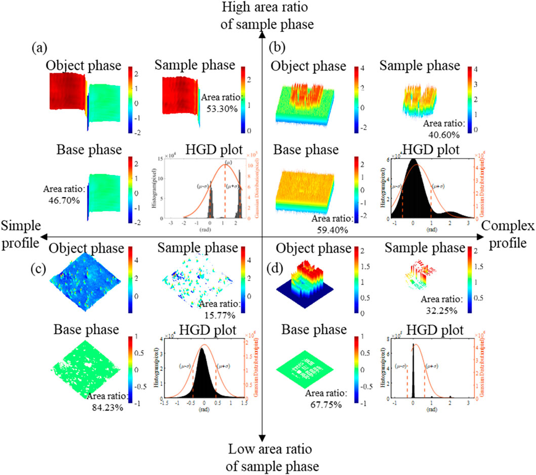
Figure 6. Classify the common phase distributions and histogram and Gaussian distributions (HGD) plots in DH according to the area ratio and profile of the sample phases: (A) The stepped phase with a large area of phase difference and simple profile with the HGD plot shows histogram converging around
For the removal of aberrations, based on the distribution of the target phase, the exact polynomial coefficients are usually obtained for the separation or minimization of the aberrations. Using a quantitative evaluation metric of maximum-minus-minimum, Wang et al. constructed a compensation function based on the reconstruction distance to remove aberration automatically (Wang et al., 2019). The quadratic phase aberration is eliminated by finding the extreme point of the metric to obtain the optimal reconstruction distance. By observing the distribution characteristics of the target phase, Chen et al. proposed a method for automatic phase aberrations elimination method based on Gaussian 1σ-criterion and histogram segmentation technique, where adaptive aberration compensation is based on the phase imitation and metric optimization method (Chen et al., 2023a; Schnars and Jüptner, 2002). Based on the characteristics of the phase HGD plots, the proposed method adaptively compensates for the common phases as illustrated in Figure 6 and eliminates the influence of the sample phase when the sample phase versus the total area of image is less than 50%. It also introduces the weighted least squares to improve the efficiency of surface fitting. For cases where the sample phase ratio is higher than 50%, the phase information is partially differentiated along the x-axis and y-axis, and the low-order signals are filtered out and restored to the imitation phase, so as to achieve accurate compensation, where previous methods have failed to solve.
To increase efficiency of aberration removal, an automatic aberration compensation approach is proposed based on the principal component analysis (PCA) (Zuo et al., 2013a; Sun et al., 2016). However, it corrects spherical/elliptical aberration only and disregards the higher order aberrations. Deep learning methods have been applied in aberration compensation in DH (Nguyen et al., 2017; Hadad et al., 2023). The traditional DH solves the phase aberration compensation problem by manually detecting the background for quantitative measurement. This would be a drawback in real time implementation and for dynamic processes such as quantification of real time cell migration. Deep learning methods are generally enabled by supervised learning with CNNs, DNNs, Y4-Net, et al. using labelled/label-free images, such as object-background segmentation images or aberration-free images to obtain the ground truth for the training.
Nguyen et al. (Nguyen et al., 2017) proposed a novel method that combines a supervised deep learning technique with convolutional neural network (CNN) and Zernike polynomial fitting (ZPF). The deep learning CNN is implemented to perform automatic background region detection that allows for ZPF to compute the self-conjugated phase to compensate for most aberrations. The network process typically takes only a fraction of a second for inference without the need for any iterations and manual intervention.
2.1.3 Phase aberration elimination with dual-wavelength
Single-wavelength DH is limited in measuring complex or highly rough surface profile. Dual-wavelength digital holography is proposed with the improvement of tunable laser performance, and the morphology measurement range of dual-wavelength digital holography can be expanded from a few microns to millimeters. In the cases of dual-/multi-wavelength hologram recording, the same optical path will be used to create holograms of different wavelengths as shown in Figure 7A. The dual-wavelength holography operates by combing multiple single-wavelength lasers to merge multiple light waves into the same optical path using a beam splitter or fiber coupler, in which different wavelengths of holograms are photographed sequentially (Di et al., 2000; Khoo et al., 2020). The phase map is obtained by subtracting two phases corresponding to two different wavelengths. However, the filtering of the spectrum in the frequency domain will result in out-of-focus information. As shown in Figure 7B, in the phase solving stage (Guo et al., 2018), Deformation of objects caused by external vibrations, tilting caused by off-axis structures (Hsieh and Kuo, 2020), and changes in background light will introduce phase distortion and Gaussian noise. Based on the method of linear regression (Shan et al., 2019; Wang et al., 2017), phase retrieval is the linear relationship between the two phase maps to avoid the noise amplification caused due to the phase subtraction of the phase maps (Kemao, 2007) or the Gaussian noise reduction method (Piniard et al., 2021), which removes Gaussian noise.
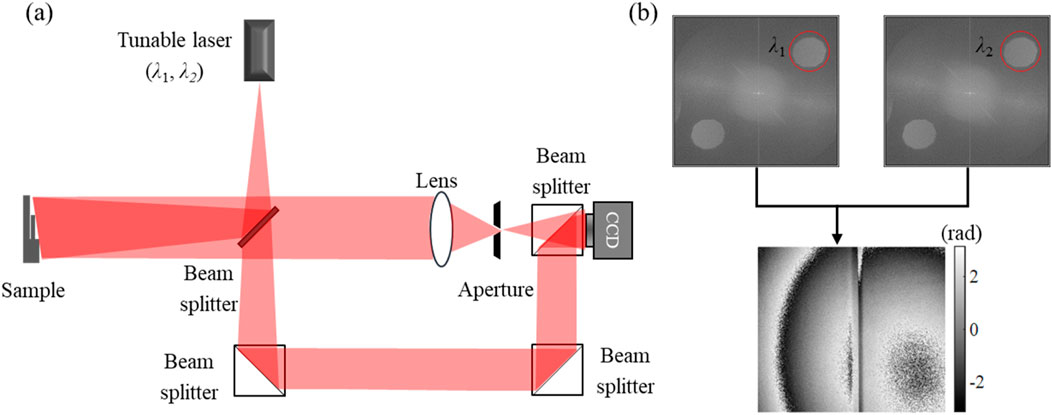
Figure 7. (A) Tunable laser-based dual-wavelength optical path system. (B) Transitions from
The chromatic aberration will occur once multi-wavelength shares the same imaging plane. Owing to the chromatic aberrations, the non-negligible longitudinal image shift will occur in the numerical reconstruction process. Commonly used methods to remove phase aberrations for dual-wavelength DH include optical path compensation (Guo and Wang, 2017), phase mask (Colomb et al., 2006c), surface fitting (Ren et al., 2019), double exposure (Khodadad et al., 2014), and the application of deep learning to increase the accuracy and speed of aberration removal (Wang et al., 2020).
In on-axis holography, due to the simple structure of the optical path, the acquisition capability of the image sensor can be fully utilized to obtain high-quality holograms, and the redundant fringe information can be eliminated iteratively through phase shift technology and the influence of the overlap between the conjugate image and the zeroth-order image can be eliminated for aberration removal (Kumar et al., 2009; Gao et al., 2021; Tahara et al., 2015; Wang H. et al., 2018; Zhou et al., 2009). In order to achieve real-time measurements, some investigators have proposed single-shot dual-wavelength digital holography (SSDWDH) as shown in Figure 8, which allows high-precision and high-depth field profile detection by setting different off-axis angles (Khodadad et al., 2015; Kumar et al., 2020; Min et al., 2012) or using the polarization characteristics of the laser (Guo and Wang, 2017; Abdelsalam et al., 2011; Abdelsalam and Kim, 2012; Kühn et al., 2007). As shown in Figure 8B, the obtained quantitative phase map calculated with the synthetic wavelength will introduce errors in spectrum selection. Especially, the errors in the reconstruction process can introduce distortions such as spherical aberrations, astigmatism, coma, and chromatic aberration.
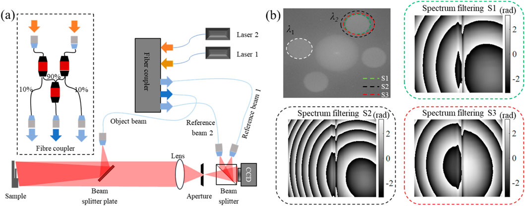
Figure 8. (A) Single-shot dual-wavelength digital holography (SSDWDH) system. (B) Effect of manual spectrogram selection on phase reconstruction, S1, S2, and S3 represent the spectrum selection of green, black, and red elliptical dotted lines, respectively. Choosing the right filtering on the spectrum can reduce the degree of aberration.
The one-shot dual-wavelength interferogram is shown in Figure 8A, where the expression of the interferogram intensity is written as:
where
Fourier transformation of the hologram yields two pairs of positive and negative primary spectrum, as shown in Figure 9A. The phase difference is proportional to the height of the object’s profile, which is manifested as Equation 7:
where
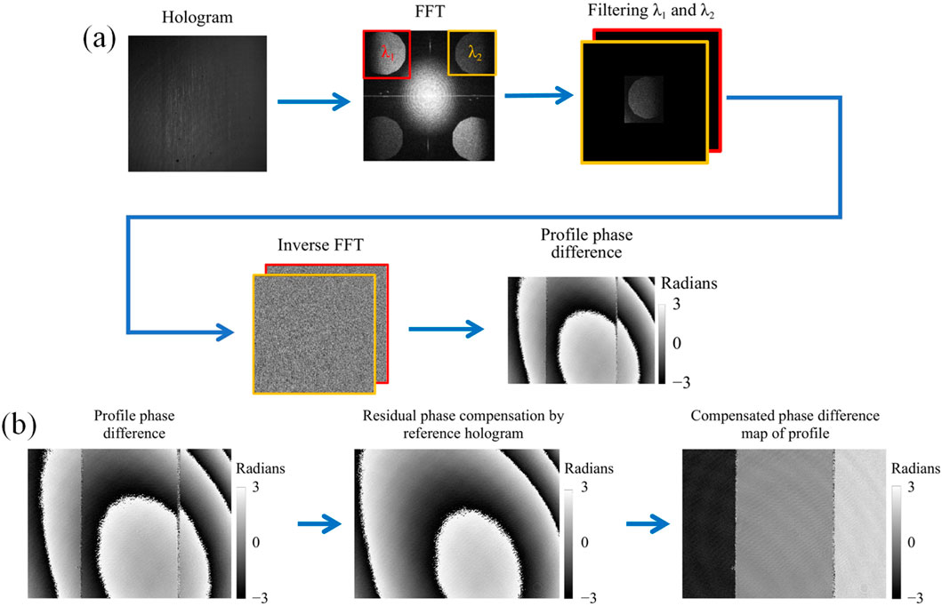
Figure 9. (A) Phase difference and profile reconstruction algorithm generated by wavelengths
Claus et al. demonstrated a dual-wavelength digital holographic interferometry based on a highly spectrally stable dual VCSEL (vertical-cavity surface-emitting laser) light source (Claus et al., 2021). They imaged the hologram of reference object without the step sample, subtracting the background phase information to obtain a clean step-type phase information as shown in Figure 9B.
The tunable laser in Figure 7A needs to emit two wavelengths of lasers sequentially, which cannot achieve real-time topography detection, and the two reference lights in Figure 8A need to be transmitted to the CCD at different angles, which is easy to introduce aberrations during spectral filtering. Replacing the laser and CCD in Figure 7A with an RGB laser and a color camera, respectively, solves this problem, greatly improving the efficiency of dual-wavelength interference. Color digital holography (Claus et al., 2021) or RGB digital holography (Min et al., 2014), and further real-time measurements can be achieved by combining the color information of light with off-axis angle (Min et al., 2012) or polarization information (Min et al., 2014). In addition, because coherent light is sensitive to defects in the optical path and prone to speckle noise, the use of low-coherence light sources is promising to obtain high quality phase maps through the use of cost effect LED light sources (Jeon et al., 2016).
2.2 Deformation phase in dual digital holograms
2.2.1 Quantitative calibration of deformation
One of main applications of the dual-digital-hologram is to study the deformation. Deformation can be detected by the use of phase differences. The interferogram recorded by the CCD after deformation can be expressed as:
where
The complex amplitude information of the phase difference
Schedin et al. (Schedin et al., 1999) used a Ruby laser to simultaneously record the z-axis deformation and x/y-axis deformation of the object using a combination of mirrors, beam-splitters, and single-mode fibers. As shown in Figure 10A, the object is illuminated from three different directions, where each optical path is matched with three reference beams such that three independent digital holograms are formed and added incoherently in one single CCD image. Figure 10B illustrates the spectrogram obtained from the hologram, which contains a zeroth-order spectrum and three pairs of positive- and negative-first order spectra. Before and after deformation, the optical phase difference between the two recordings taken for each hologram is quantitatively evaluated by the Fourier-transform method so that a set of three phase maps is obtained, representing the deformation along three sensitivity vectors.
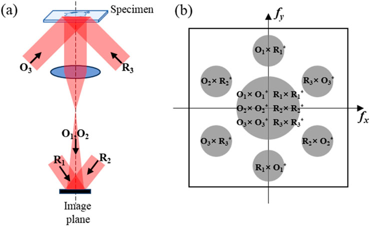
Figure 10. Deformation in three directions recorded by two holograms. (A) Schematic diagram of a system that simultaneously detects deformations in three directions. (B) Spectrogram obtained from a hologram generated by three pairs of interference of object beams and reference beams incident onto the CCD, where the density of information recording is greatly improved.
Li et al. (Li et al., 2021) proposed an efficient and synchronous 3D deformation measurement method based on digital speckle pattern interferometry (DSPI) and digital shear speckle interference (DSSPI). These two methods used a single CCD and two lasers to capture the speckle patterns from three sensitive directions simultaneously, which simplified the optical arrangement with reduced system cost, and improved the detection efficiency effectively. Based on the characteristics of shear speckle interferometry, which can directly obtain the derivative of motion information, real-time three-direction motion detection can be realized.
The motion detection information (μm or nm) obtained by DH is displayed in phase (rad), but there is a lack of effective calibration techniques to connect μm and rad for movement in the x, y, and z-axes. To exploit the advantages of those optical techniques and enhance the confidence in the data from the optical system, Long et al. (Long et al., 2023) proposed a physical reference material (PRM) that can generate a deformation field with submicron uncertainty. The PRM is a circular plate of composite structure including a central rod and the peripheral annular plate clamped at the edge, the central rod of which has merely displacement and no deformation under displacement loading. The displacement of the central area of the PRM is used for calibration, which provides connection to the national standard for length.
2.2.2 Quantitative analysis of deformation
To identify the location, shape, and quantitative analysis of defects on the surface and subsurface of objects, a nonlinear force analysis of the overall deformation is constituted under the external excitation (dePolo et al., 2021). When the surface of an object is artificially excited, the inhomogeneity of the subsurface and the body of the object goes through changes in optical displacement that is simultaneously captured in full-field interferometry. The influence of thermal energy (Kosma et al., 2018; Tornari et al., 2020; Rippa et al., 2021) and acoustic wave (Shen et al., 2004; Wang et al., 2013) therefore can be used to detect the defects on surface and subsurface of these objects. Vibration experiments (Tornari, 2019; Bernikola et al., 2009; Tornari et al., 2008) are also used to simulate the vibration of artifacts in multi-directions and at board-band frequencies during transportation. The above-mentioned external influences will cause a change in the optical path difference in the interference field, resulting in a fringe pattern of the phase. Based on the fringe patterns, the deformation of the surface of the object can be restored, and the damage degree of the defect can be evaluated by qualitative or quantitative methods.
Tornari et al. (Tornari, 2014; Tornari, 2019; Bernikola et al., 2009; Tornari et al., 2008; Tornari, 2022; Tornari, 2007; Tornari et al., 2015; Tornari et al., 2017; Trillo et al., 2010b) confirmed the correlation between the appearance of the fringe patterns and the cause of the defect. As shown in Figure 11A, the approach adopted is a general description of the morphology of edges for a common type of internal defect, interlayer debonding, known as detachment and fissures in art conservation. It shows that any defect-indicative fringe patterns can serve as a direct visual control of the structural condition in the inspection of works of art. In Figure 11B, the fringe patterns are overlapped with the image acquired in the field of view (FOV). By using the “Fringe pattern classification” in Table 1, the location and shape of defect information is qualitatively analysed by observing the abnormal parts of the fringe patterns.
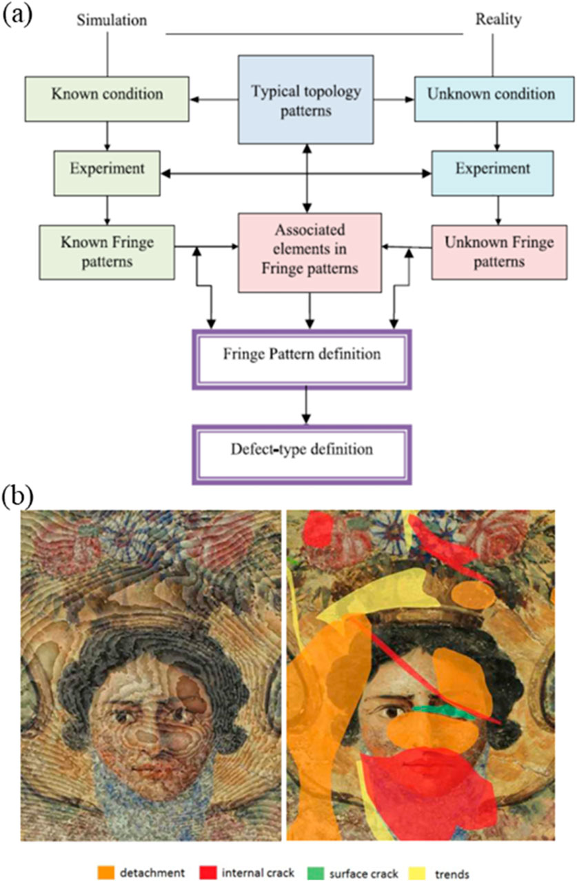
Figure 11. (A) Method to validate unknown fringe patterns in artwork documentation; (B) an overlay exemplary interferogram with the fresco and the risk assessment map. [Reprinted/Adapted] with permission from ref (Trillo et al., 2012) 2012 Published by Springer Nature BV.
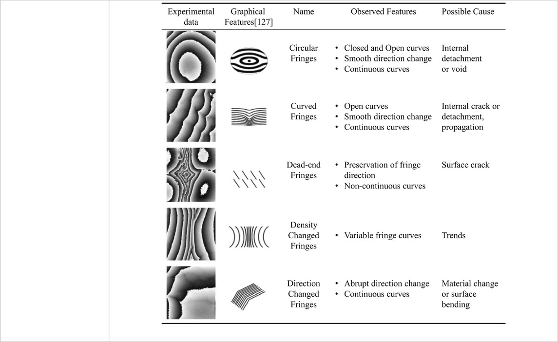
Table 1. Fringe pattern classification.
The fringe patterns have typical classification associated with defects. Through a large number of validation from the fringe patterns obtained by the preset defects, the comparative identification of the fringes and defects can be realized, so as to obtain the fringe pattern classification in Table 1. The defective area has abnormal structural or material characteristics so that the mechanical freedom under external excitation is higher than the normal area. The energy waves will excite both the local-body and the whole-body (Tornari, 2022). The energy wave is incident on the mural surface in the form of a spherical wave, and the deformation can be regarded as phase contrast information, which thus is helpful for recognition of the objects without the need of labels.
From the deformation calibration experiment in Figure 11, it can be observed that the deformation is similar to spherical waves. Compared to optical spherical waves, the form of energy waves is mainly present in the deformation of the surface of the object (Chen et al., 2024; Chen et al., 2023c). The unwrapped phase is
where
Deformation signifies changes in the mechanical integrity or physicochemical composition of materials, leading to the deterioration of the constitution and construction of objects. The fringe patterns are mostly useful for the whole-body deformation (Tornari, 2022), which would mask minor abnormalities in the local-body. Therefore, it is possible to combine the qualitative identification of the fringe pattern with the quantitative analysis of the phase of the localized region. As shown in Figure 12A, the cause of the global defects in the detection area can be obtained using the classification in Table 1. The local-body phase shown in Figure 12C reveals the quantitative information of the defect. Highlights from the solid red lines and the dotted blue lines shown in Figure 12D allows for a qualitative and quantitative comprehensive analysis of the defects.
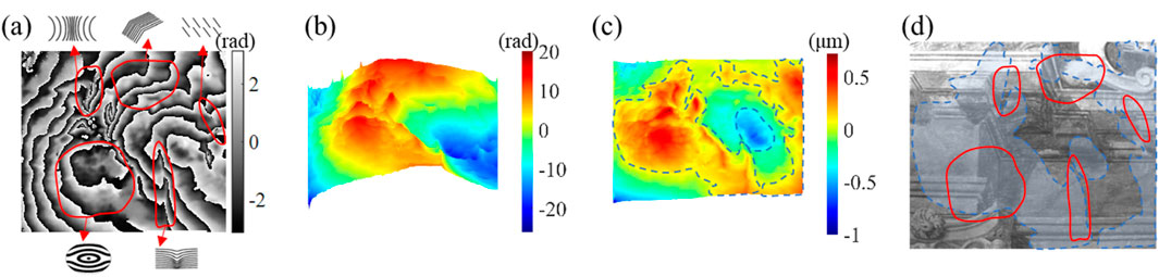
Figure 12. Comprehensive qualitative and quantitative analysis of defects in the detection area. (A) obtained fringe patterns map, it shows five typical fringe species: circular fringes; curved fringes; density changed fringes; direction changed fringes; dead-end fringes (Tornari et al., 2012); (B) unwrapped phase map; (C) deformation map of local-body, with abnormal areas marked by blue dotted lines; (D) original photo of the sampling fresco area, in which the defect areas marked in Figures 12A, C are overlapped.
2.2.3 Local deformation separation from the whole phase mixed with background
For dual digital hologram analysis, the object deformation leads to changes relative to the background. In the optical path shown in Figure 7, the reconstructed phase information is mixed with the topography information of the object and the deformation information disturbed by the external environment. There are some special cases, such as in Figure 13, where the analyte is a step-shaped sample that is pasted on the background plate and slides relative to the background plate during the test. The first hologram
where
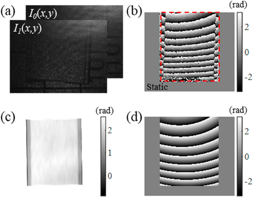
Figure 13. A special case of aberration elimination. (A) Two holograms taken before and after the local deformation of a dual-wavelength object in a static experiment; (B) The wrapped phase obtained by phase subtraction; (C) separated step-type object information; (D) isolated deformation information in terms of fringes.
Using the Fourier carrier algorithm, the phase difference between the two holograms can be obtained:
where
The phase difference
2.3 Location and reversion of defects within materials
Multiple holograms involve the collection of multiple holograms. Given the multiple K holograms, K-1 wrapped phases with fringes can be obtained based on the principle of phase subtraction. As shown in Figure 3, in these wrapped phases, there are regular changes due to defects within the material or high-speed motion. Defects of the material require analysis of the deformation fringes in these holograms.
Trillo et al. proposed a hybrid technique aimed at non-destructive testing of materials, through a combination of acoustic, optical, and numerical methods to obtain information inside the material and thus assessing its integrity (Trillo et al., 2010a; Trillo et al., 2011; Trillo et al., 2010b). Sonar is performed on the specimen with a narrow band compression sound wave of short pulses. The wave travels through the material, probes its interior, and eventually appears on the opposite surface. Pulsed digital holography interferometry (pulsed television holography) is used to measure the surface displacement caused by the arrival of the continuous wave surface of the wavefront. The acoustic amplitude and phase of the wavefront on the surface can be obtained by performing 3D Fourier transform processing on the measured data.
The 3D Fourier transform is applied for phase retrieval as shown in Figure 14. The general expression of a hologram with spatial carrier, recorded with single pulse illumination, for a given instant
where
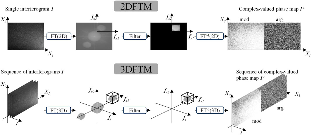
Figure 14. Summary of the 2D Fourier transform method (2DFTM) and the 3D Fourier transform method (3DFTM), in which mod and arg represent amplitude and phase, repectively (Trillo et al., 2010a).
Similar to the traditional Fourier transform, Equation 9 shows the spectral characteristics of the positive and negative first and zeroth order in the spectrum after the 3D Fourier transform. The defective and non-defective specimens were utilized to validate the technique (Trillo et al., 2010a). In defective specimens, the technique has the ability to locate the approximate size and location of the defect as long as the transverse dimensions of the defect are large enough compared to the acoustic wavelength employed. Based on the Rayleigh-Sommerfeld diffraction formula, the above acoustic wave amplitude and phase are conducted in the opposite direction, thus the defect is focused at the positive order of the t axis, so as to realize the defect location.
The image sampling frequency of 3D Fourier transform is 17–25fps for ordinary CCD cameras. When detecting axial defects, the positioning accuracy is in the millimeter range. In order to improve the positioning accuracy and multi-defect simultaneous positioning, Goursolle et al. (Goursolle et al., 2007; Goursolle et al., 2008) demonstrated the feasibility of using the nonlinear features extracted from non-linear elastic wave spectroscopy (NEWS) combined with the time reversal (TR) method to achieve precise defect imaging. Geometry and some material characteristics of the 2D specimen (300 mm × 500 mm aluminum sample) are shown in Figure 15. There are positive and negative excitation signals serving as the input, which are transmitted in the measured sample. Due to the hysteresis and expansion characteristics of the defects, the extreme changes in stress will produce linear and nonlinear deformation results, and the deformation results will be added and subtracted. If the added phase is not zero, it indicates an internal defect. The deformation result is converted into excitation. Consequently, excitation is transmitted back reversely, where the defect location information is obtained after the time reversal algorithm.
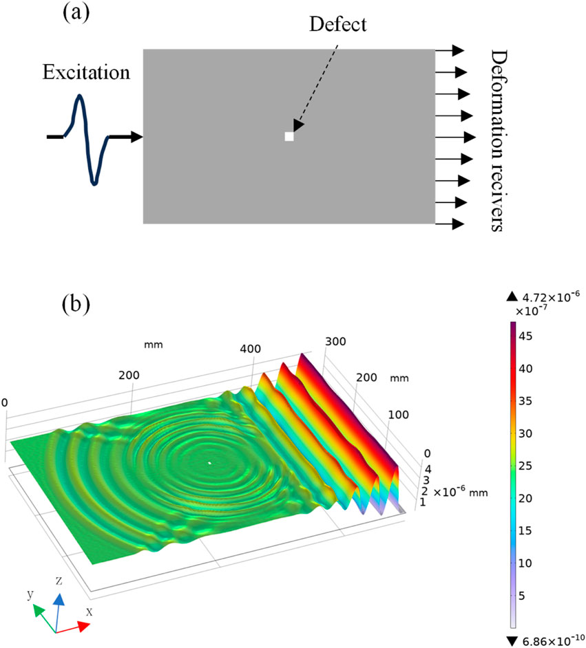
Figure 15. The location of internal defects is obtained based on the time reversal method. (A) Geometry of simulation with source, deformation receivers, defect positions (Goursolle et al., 2008); (B) Matrix of the maximum of stress with a rebroadcasting of non-linear signature extracted with harmonic filtering.
3 Conclusion
This paper have discussed phase aberration removal, deformation analysis, and location of defects from a single hologram, dual- and multiple-holograms. For a single hologram obtained from on-axis/off-axis, static/dynamic or single/dual wavelengths, the focus is to eliminate or compensate phase errors. With prior knowledge, the corresponding quadratic aberration coefficient can be obtained through leveraging optical setup, spectrum, and the fringe information. Without prior knowledge, polynomial coefficient optimization technology, phase separation technology, and deep learning methods have been proposed to remove phase aberration to obtain aberration-free surface. These technologies also can be extended to the dual-wavelength or multi-wavelength situations for precise profile reconstruction. For two or more holograms, analysis on phase difference has become interesting, and the focus is more on its quantitative analysis corresponding to the deformation or defects. For example, the strain distribution of the defect location is separated from the complex fringes to realize the lateral and axial quantification of the defect. Using techniques such as three-dimensional Fourier transform, or time reversal method, the location of defects can be retrieval from holograms. Future work will enable digital holography to provide high precision, high resolution, rapid quantitative and intelligent phase imaging ability, which will continue to inspire diverse applications.
Author contributions
ZC: Conceptualization, Data curation, Formal Analysis, Writing–original draft. WZ: Resources, Supervision, Validation, Writing–review and editing. ZG: Writing–review and editing. YY: Funding acquisition, Project administration, Writing–review and editing. HZ: Conceptualization, Writing–review and editing. T-CP: Writing–review and editing, Visualization.
Funding
The author(s) declare that financial support was received for the research, authorship, and/or publication of this article. This project was supported by the National Natural Science Foundation of China (Nos 62475141 and 52075314).
Conflict of interest
The authors declare that the research was conducted in the absence of any commercial or financial relationships that could be construed as a potential conflict of interest.
The author(s) declared that they were an editorial board member of Frontiers, at the time of submission. This had no impact on the peer review process and the final decision.
The reviewer JS declared a past co-authorship with the author T-CP to the handling editor.
Publisher’s note
All claims expressed in this article are solely those of the authors and do not necessarily represent those of their affiliated organizations, or those of the publisher, the editors and the reviewers. Any product that may be evaluated in this article, or claim that may be made by its manufacturer, is not guaranteed or endorsed by the publisher.
References
Abdelsalam, D. G., and Kim, D. (2012). Real-time dual-wavelength digital holographic microscopy based on polarizing separation. Opt. Commun. 285, 233–237. doi:10.1016/j.optcom.2011.09.044
Abdelsalam, D. G., Magnusson, R., and Kim, D. (2011). Single-shot, dual-wavelength digital holography based on polarizing separation. Appl. Opt. 50, 3360. doi:10.1364/AO.50.003360
Andrés, N., Pinto, C., Lobera, J., López, A. M., Palero, V., and Arroyo, M. P. (2020). Digital holography applied to simultaneously measure the shape and the radial deformation of a blood vessel (ex-vivo). Opt. and Laser Technol. 129, 106304. doi:10.1016/j.optlastec.2020.106304
Arai, Y. (2016). Simultaneous in-plane and out-of-plane deformation measurement by speckle multi-recording method. Measurement 91, 582–589. doi:10.1016/j.measurement.2016.05.037
Bernikola, E., Nevin, A., and Tornari, V. (2009). Rapid initial dimensional changes in wooden panel paintings due to simulated climate-induced alterations monitored by digital coherent out-of-plane interferometry. Appl. Phys. A 95, 387–399. doi:10.1007/s00339-009-5096-3
Chen, S., Wu, J., Chen, Z., Shao, L., and Zhou, W. 2023d, Imaging of MEMS morphology and deformation based on digital holography, 20. doi:10.1117/12.2686805
Chen, Z., Zhou, W., Duan, L., Zhang, H., Zheng, H., Xia, X., et al. (2023b). Automatic elimination of phase aberrations in digital holography based on Gaussian 1σ-criterion and histogram segmentation. Opt. Express 31, 13627. doi:10.1364/OE.486890
Chen, Z., Zhou, W., Qu, L., Li, G., Yu, Y., and Tornari, V. (2024). Quantification analysis of mural defects in digital holography with fundamental voice excitation based on local phase field separation. Opt. and Laser Technol. 172, 110506. doi:10.1016/j.optlastec.2023.110506
Chen, Z., Zhou, W., Yu, Y., Tornari, V., and Artioli, G. (2023c). Defect isolation from whole to local field separation in complex interferometry fringe patterns through development of weighted least-squares algorithm. Digital 4, 104–113. doi:10.3390/digital4010004
Chen, Z., Zhou, W., Zhang, H., and Yu, Y. (2023a). Phase aberration adaptive compensation in digital holography based on phase imitation and metric optimization. Opt. Express 31, 21048. doi:10.1364/OE.494302
Claus, D., Alekseenko, I., Grabherr, M., Pedrini, G., and Hibst, R. (2021). Snap-shot topography measurement via dual-VCSEL and dual wavelength digital holographic interferometry. Light Adv. Manuf. 2, 1. doi:10.37188/lam.2021.029
Colomb, T., Cuche, E., Charrière, F., Kühn, J., Aspert, N., Montfort, F., et al. (2006a). Automatic procedure for aberration compensation in digital holographic microscopy and applications to specimen shape compensation. Appl. Opt. 45, 851. doi:10.1364/AO.45.000851
Colomb, T., Kühn, J., Charrière, F., Depeursinge, C., Marquet, P., and Aspert, N. (2006c). Total aberrations compensation in digital holographic microscopy with a reference conjugated hologram. Opt. Express 14, 4300. doi:10.1364/OE.14.004300
Colomb, T., Montfort, F., Kühn, J., Aspert, N., Cuche, E., Marian, A., et al. (2006b). Numerical parametric lens for shifting, magnification, and complete aberration compensation in digital holographic microscopy. J. Opt. Soc. Am. A 23, 3177. doi:10.1364/JOSAA.23.003177
Coppola, G., Di Caprio, G., Gioffré, M., Puglisi, R., Balduzzi, D., Galli, A., et al. (2010). Digital self-referencing quantitative phase microscopy by wavefront folding in holographic image reconstruction. Opt. Lett. 35, 3390. doi:10.1364/OL.35.003390
Cuche, E., Bevilacqua, F., and Depeursinge, C. (1999). Digital holography for quantitative phase-contrast imaging. Opt. Lett. 24, 291. doi:10.1364/OL.24.000291
Dekiff, M., Berssenbrügge, P., Kemper, B., Denz, C., and Dirksen, D. (2015). Simultaneous acquisition of 3D shape and deformation by combination of interferometric and correlation-based laser speckle metrology. Biomed. Opt. Express 6, 4825. doi:10.1364/BOE.6.004825
Deng, D., Peng, J., Qu, W., Wu, Y., Liu, X., He, W., et al. (2017a). Simple and flexible phase compensation for digital holographic microscopy with electrically tunable lens. Appl. Opt. 56, 6007. doi:10.1364/AO.56.006007
Deng, D., Qu, W., He, W., Wu, Y., Liu, X., and Peng, X. (2017b). Off-axis tilt compensation in common-path digital holographic microscopy based on hologram rotation. Opt. Lett. 42, 5282. doi:10.1364/OL.42.005282
dePolo, G., Walton, M., Keune, K., and Shull, K. R. (2021). After the paint has dried: a review of testing techniques for studying the mechanical properties of artists’ paint. Herit. Sci. 9, 68. doi:10.1186/s40494-021-00529-w
Di, J., Song, Y., Xi, T., Zhang, J., Li, Y., Ma, C., et al. (2000). Improvement of phase measurement accuracy and stability in dual-wavelength common-path digital holographic microscopy. in, ed. A. K. Asundi (Singapore, Singapore), 104491W. doi:10.1117/12.2270774
Di, J., Zhao, J., Sun, W., Jiang, H., and Yan, X. (2009). Phase aberration compensation of digital holographic microscopy based on least squares surface fitting. Opt. Commun. 282, 3873–3877. doi:10.1016/j.optcom.2009.06.049
Doblas, A., Hincapie-Zuluaga, D., Saavedra, G., Martínez-Corral, M., and Garcia-Sucerquia, J. (2015). Physical compensation of phase curvature in digital holographic microscopy by use of programmable liquid lens. Appl. Opt. 54, 5229. doi:10.1364/AO.54.005229
Enloe, L. H., Murphy, J. A., and Rubinstein, C. B. B. S. T. J. (1966). Briefs Hologram transmission via television. Bell Syst. Tech. J. 45, 333–335. doi:10.1002/j.1538-7305.1966.tb00026.x
Espinosa, J., Pérez, J., Mas, D., and Illueca, C. (2011). Weighted Zernike polynomial fitting in steep corneas sampled in Cartesian grid. J. Mod. Opt. 58, 1710–1715. doi:10.1080/09500340.2011.556263
Ferraro, P., Alferi, D., De Nicola, S., De Petrocellis, L., Finizio, A., and Pierattini, G. (2006). Quantitative phase-contrast microscopy by a lateral shear approach to digital holographic image reconstruction. Opt. Lett. 31, 1405. doi:10.1364/OL.31.001405
Fu, Y., Pedrini, G., Hennelly, B. M., Groves, R. M., and Osten, W. (2009). Dual-wavelength image-plane digital holography for dynamic measurement. Opt. Lasers Eng. 47, 552–557. doi:10.1016/j.optlaseng.2008.10.002
Gao, C., Gao, Z., Niu, Y., Wang, X., Zhao, J., and Deng, L. (2021). An improved large-field microscopic speckle interferometry system for dynamic displacement measurement of MEMS. Photonics 8, 271. doi:10.3390/photonics8070271
Goursolle, T., Callé, S., Dos Santos, S., and Bou Matar, O. (2007). A two-dimensional pseudospectral model for time reversal and nonlinear elastic wave spectroscopy. J. Acoust. Soc. Am. 122, 3220–3229. doi:10.1121/1.2799900
Goursolle, T., Dos Santos, S., Bou Matar, O., and Callé, S. (2008). Non-linear based time reversal acoustic applied to crack detection: simulations and experiments. Int. J. Non-Linear Mech. 43, 170–177. doi:10.1016/j.ijnonlinmec.2007.12.008
Guo, H. (2011). A simple algorithm for fitting a Gaussian function [DSP tips and tricks]. IEEE Signal Process Mag. 28, 134–137. doi:10.1109/MSP.2011.941846
Guo, R., and Wang, F. (2017). Compact and stable real-time dual-wavelength digital holographic microscopy with a long-working distance objective. Opt. Express 25, 24512. doi:10.1364/OE.25.024512
Guo, R., Zhang, W., Liu, R., Duan, C., and Wang, F. (2018). Phase unwrapping in dual-wavelength digital holographic microscopy with total variation regularization. Opt. Lett. 43, 3449. doi:10.1364/OL.43.003449
Hadad, B., Froim, S., Yosef, E., Giryes, R., and Bahabad, A. (2023). Deep learning in optics—a tutorial. J. Opt. 25, 123501. doi:10.1088/2040-8986/ad08dc
Hansel, T., Grunwald, R., Reimann, K., Bonitz, J., Kaufmann, C., and Griebner, U. (2009). Deformation measurements of high-speed MEMS with combined two-wavelength single-pulse digital holography and single phase reconstruction using subpicosecond pulses. IEEE J. Sel. Top. Quantum Electron 15, 1351–1358. doi:10.1109/JSTQE.2009.2017032
Hart, M. R., Conant, R. A., Lau, K. Y., and Muller, R. S. (2000). Stroboscopic interferometer system for dynamic MEMS characterization. J. Microelectromech Syst. 9, 409–418. doi:10.1109/84.896761
Hsieh, H.-L., and Kuo, P.-C. (2020). Heterodyne speckle interferometry for measurement of two-dimensional displacement. Opt. Express 28, 724. doi:10.1364/OE.382494
Huang, Z., and Cao, L. (2023). Phase aberration separation for holographic microscopy by alternating direction sparse optimization. Opt. Express 31, 12520. doi:10.1364/OE.488201
Huang, Z., Yang, F., Liu, B., Liu, Y., and Cao, L. (2023). Aberration-free synthetic aperture phase microscopy based on alternating direction method. Opt. Lasers Eng. 160, 107301. doi:10.1016/j.optlaseng.2022.107301
Jeon, S., Cho, J., Jin, J., Park, N.-C., and Park, Y.-P. (2016). Dual-wavelength digital holography with a single low-coherence light source. Opt. Express 24, 18408. doi:10.1364/OE.24.018408
Kemao, Q. (2007). Two-dimensional windowed Fourier transform for fringe pattern analysis: principles, applications and implementations. Opt. Lasers Eng. 45, 304–317. doi:10.1016/j.optlaseng.2005.10.012
Khodadad, D., Bergström, P., Hällstig, E., and Sjödahl, M. (2014). Single shot dual-wavelength digital holography: calibration based on speckle displacements. Int. J. Optomechatronics 8, 326–339. doi:10.1080/15599612.2014.942932
Khodadad, D., Bergström, P., Hällstig, E., and Sjödahl, M. (2015). Fast and robust automatic calibration for single-shot dual-wavelength digital holography based on speckle displacements. Appl. Opt. 54, 5003. doi:10.1364/AO.54.005003
Khoo, T. C., Sharikova, A., and Khmaladze, A. (2020). Dual wavelength digital holographic imaging of layered structures. Opt. Commun. 458, 124793. doi:10.1016/j.optcom.2019.124793
Kosma, K., Andrianakis, M., Hatzigiannakis, K., and Tornari, V. (2018). Digital holographic interferometry for cultural heritage structural diagnostics: a coherent and a low-coherence optical set-up for the study of a marquetry sample. Strain 54, e12263. doi:10.1111/str.12263
Kühn, J., Colomb, T., Montfort, F., Charrière, F., Emery, Y., Cuche, E., et al. (2007). Real-time dual-wavelength digital holographic microscopy with a single hologram acquisition. Opt. Express 15, 7231. doi:10.1364/OE.15.007231
Kumar, M., Quan, X., Awatsuji, Y., Tamada, Y., and Matoba, O. (2020). Single-shot common-path off-axis dual-wavelength digital holographic microscopy. Appl. Opt. 59, 7144. doi:10.1364/AO.395001
Kumar, U. P., Bhaduri, B., Kothiyal, M. P., and Mohan, N. K. (2009). Two-wavelength micro-interferometry for 3-D surface profiling. Opt. Lasers Eng. 47, 223–229. doi:10.1016/j.optlaseng.2008.04.005
Lee, J.-Y., Lu, M.-P., Lin, K.-Y., and Huang, S.-H. (2012). Measurement of in-plane displacement by wavelength-modulated heterodyne speckle interferometry. Appl. Opt. 51, 1095. doi:10.1364/AO.51.001095
Leith, E. N., and Upatnieks, J. (1964). Wavefront reconstruction with diffused illumination and three-dimensional objects. J. Opt. Soc. Am. 54, 1295. doi:10.1364/JOSA.54.001295
Li, P., Cai, P., Long, J., Liu, C., and Yan, H. (2018a). Measurement of out-of-plane deformation of curved objects with digital speckle pattern interferometry. Chin. Opt. Lett. 16, 111202. doi:10.3788/COL201816.111202
Li, S., Ma, J., Chang, C., Nie, S., Feng, S., and Yuan, C. (2018b). Phase-shifting-free resolution enhancement in digital holographic microscopy under structured illumination. Opt. Express 26, 23572. doi:10.1364/OE.26.023572
Li, S., Yin, D., Feng, S., Ma, J., Ma, Q., and Yuan, C. (2019). “Phase aberration compensation for resolution enhancement in digital holographic microscopy under structured illumination,” in Biophotonics congress: optics in the life sciences congress 2019 (BODA,BRAIN,NTM,OMA,OMP), JT4A.28. Tucson, Arizona: OSA, JT4A.28. doi:10.1364/BODA.2019.JT4A.28
Li, Z., Zhong, P., Chen, Y., Tang, X., Gao, Y., and Hu, H. (2021). Simultaneous measurement of three-dimensional deformation based on digital speckle pattern interferometry technology. Opt. Commun. 480, 126423. doi:10.1016/j.optcom.2020.126423
Lipiainen, L., Kokkonen, K., Novotny, S., Shavrin, I., Ludvigsen, H., and Kaivola, M. (1997). “Full-field characterization of surface vibrations in microacoustic components by supercontinuum laser stroboscopic white-light interferometry,” in 2014 IEEE international ultrasonics symposium (chicago, IL, USA: ieee), 158–161. doi:10.1109/ULTSYM.2014.0040
Liu, C., Yu, X., and Kim, M. K. (2013). Phase aberration correction by correlation in digital holographic adaptive optics. Appl. Opt. 52, 2940. doi:10.1364/AO.52.002940
Liu, S., Lian, Q., Qing, Y., and Xu, Z. (2018a). Automatic phase aberration compensation for digital holographic microscopy based on phase variation minimization. Opt. Lett. 43, 1870. doi:10.1364/OL.43.001870
Liu, S., Lian, Q., and Xu, Z. (2019). Phase aberration compensation for digital holographic microscopy based on double fitting and background segmentation. Opt. Lasers Eng. 115, 238–242. doi:10.1016/j.optlaseng.2018.12.001
Liu, S., Xiao, W., and Pan, F. (2014). Automatic compensation of phase aberrations in digital holographic microscopy for living cells investigation by using spectral energy analysis. Opt. and Laser Technol. 57, 169–174. doi:10.1016/j.optlastec.2013.10.014
Liu, S., Zhu, W., Xu, Z., and Gao, M. (2020). Automatic and robust phase aberration compensation for digital holographic microscopy based on minimizing total standard deviation. Opt. Lasers Eng. 134, 106276. doi:10.1016/j.optlaseng.2020.106276
Liu, Y., Wang, Z., and Huang, J. (2018b). Recent progress on aberration compensation and coherent noise suppression in digital holography. Appl. Sci. 8, 444. doi:10.3390/app8030444
Long, J., Cai, P., Li, K., Guan, W., Pan, S., and Yan, H. (2023). A reference material for evaluating full-field out-of-plane deformation measurement system. Opt. Lasers Eng. 162, 107431. doi:10.1016/j.optlaseng.2022.107431
Mandracchia, B., Wang, Z., Ferraro, V., Villone, M. M., Di Maio, E., Maffettone, P. L., et al. (2019). Quantitative imaging of the complexity in liquid bubbles’ evolution reveals the dynamics of film retraction. Light Sci. Appl. 8, 20. doi:10.1038/s41377-019-0131-4
Mann, C. J., Yu, L., Lo, C.-M., and Kim, M. K. (2005). High-resolution quantitative phase-contrast microscopy by digital holography. Opt. Express 13, 8693. doi:10.1364/OPEX.13.008693
Matkivsky, V. A., Moiseev, A. A., Shilyagin, P. A., Shabanov, D. V., Gelikonov, G. V., and Gelikonov, V. M. (2016). A new method for finding optical aberrations on the basis of analysis of the object hologram without additional measurements. Radiophys. Quantum El 59, 393–404. doi:10.1007/s11141-016-9708-4
Merola, F., Mandracchia, B., Miccio, L., Memmolo, P., Bianco, V., Mugnano, M., et al. (2013a). “Recent advancements and perspective about digital holography: a super-tool in biomedical and bioengineering fields,” in Advancement of optical methods and digital image Correlation in experimental mechanics, volume 3 conference proceedings of the society for experimental mechanics series. Editors L. Lamberti, M.-T. Lin, C. Furlong, C. Sciammarella, P. L. Reu, and M. A. Sutton (Cham: Springer International Publishing), 235–241. doi:10.1007/978-3-319-97481-1_32
Merola, F., Memmolo, P., Miccio, L., Savoia, R., Mugnano, M., Fontana, A., et al. (2016). Tomographic flow cytometry by digital holography. Light Sci. Appl. 6, e16241. doi:10.1038/lsa.2016.241
Merola, F., Miccio, L., Memmolo, P., Di Caprio, G., Galli, A., Puglisi, R., et al. (2013b). Digital holography as a method for 3D imaging and estimating the biovolume of motile cells. Lab. Chip 13, 4512. doi:10.1039/c3lc50515d
Miccio, L., Alfieri, D., Grilli, S., Ferraro, P., Finizio, A., De Petrocellis, L., et al. (2007). Direct full compensation of the aberrations in quantitative phase microscopy of thin objects by a single digital hologram. Appl. Phys. Lett. 90, 041104. doi:10.1063/1.2432287
Miccio, L., Memmolo, P., Merola, F., Fusco, S., Embrione, V., Paciello, A., et al. (2014). Particle tracking by full-field complex wavefront subtraction in digital holography microscopy. Lab. Chip 14, 1129–1134. doi:10.1039/C3LC51104A
Min, J., Yao, B., Gao, P., Guo, R., Ma, B., Zheng, J., et al. (2012). Dual-wavelength slightly off-axis digital holographic microscopy. Appl. Opt. 51, 191. doi:10.1364/AO.51.000191
Min, J., Yao, B., Zhou, M., Guo, R., Lei, M., Yang, Y., et al. (2014). Phase retrieval without unwrapping by single-shot dual-wavelength digital holography. J. Opt. 16, 125409. doi:10.1088/2040-8978/16/12/125409
Min, J., Yfao, B., Ketelhut, S., Engwer, C., Greve, B., and Kemper, B. (2017). Simple and fast spectral domain algorithm for quantitative phase imaging of living cells with digital holographic microscopy. Opt. Lett. 42, 227. doi:10.1364/OL.42.000227
Nam, J., and Rubinstein, J. (2005). Weighted Zernike expansion with applications to the optical aberration of the human eye. J. Opt. Soc. Am. A 22, 1709. doi:10.1364/JOSAA.22.001709
Nguyen, T., Bui, V., Lam, V., Raub, C. B., Chang, L.-C., and Nehmetallah, G. (2017). Automatic phase aberration compensation for digital holographic microscopy based on deep learning background detection. Opt. Express 25, 15043. doi:10.1364/OE.25.015043
Nilsson, B. (2000). Simultaneous measurement of shape and deformation using digital light-in-flight recording by holography. Opt. Eng. 39, 244. doi:10.1117/1.602362
Nilsson, B. J., and Carlsson, T. E. (1997). Resolution improvements of the digital light-in-flight recording by holography method. in, eds. M. Kujawinska, R. J. Pryputniewicz, and M. Takeda (San Diego, CA), 366–374. doi:10.1117/12.498443
Ooms, T., Koek, W., and Westerweel, J. (2008). Digital holographic particle image velocimetry: eliminating a sign-ambiguity error and a bias error from the measured particle field displacement. Meas. Sci. Technol. 19, 074003. doi:10.1088/0957-0233/19/7/074003
Pan, G., and Meng, H. (2003). Digital holography of particle fields: reconstruction by use of complex amplitude. Appl. Opt. 42, 827. doi:10.1364/AO.42.000827
Piniard, M., Sorrente, B., Hug, G., and Picart, P. (2021). Theoretical analysis of surface-shape-induced decorrelation noise in multi-wavelength digital holography. Opt. Express 29, 14720. doi:10.1364/OE.423391
Rembe, C., and Muller, R. S. (2002). Measurement system for full three-dimensional motion characterization of MEMS. J. Microelectromech Syst. 11, 479–488. doi:10.1109/JMEMS.2002.803285
Ren, Z., Xu, Z., and Lam, E. Y. (1999). Phase aberration compensation in digital holographic microscopy using regression analysis. doi:10.1364/3D.2018.JTh3B.5
Ren, Z., Zhao, J., and Lam, E. Y. (2019). Automatic compensation of phase aberrations in digital holographic microscopy based on sparse optimization. Apl. Photonics 4, 110808. doi:10.1063/1.5115079
Rippa, M., Pagliarulo, V., Lanzillo, A., Grilli, M., Fatigati, G., Rossi, P., et al. (2021). Active thermography for non-invasive inspection of an artwork on poplar panel: novel approach using principal component thermography and absolute thermal contrast. J. Nondestruct Eval. 40, 21. doi:10.1007/s10921-021-00755-z
Sánchez-Ortiga, E., Doblas, A., Martínez-Corral, M., Saavedra, G., and Garcia-Sucerquia, J. (2014). Aberration compensation for objective phase curvature in phase holographic microscopy: comment. Opt. Lett. 39, 417. doi:10.1364/OL.39.000417
Sánchez-Ortiga, E., Ferraro, P., Martínez-Corral, M., Saavedra, G., and Doblas, A. (2011). Digital holographic microscopy with pure-optical spherical phase compensation. J. Opt. Soc. Am. A 28, 1410. doi:10.1364/JOSAA.28.001410
Saucedo, A. T., Santoyo, F. M., De La Torre Ibarra, M., Pedrini, G., and Osten, W. (2006). Simultaneous two-dimensional endoscopic pulsed digital holography for evaluation of dynamic displacements. Appl. Opt. 45, 4534. doi:10.1364/AO.45.004534
Schedin, S., Pedrini, G., Tiziani, H. J., and Mendoza Santoyo, F. (1999). Simultaneous three-dimensional dynamic deformation measurements with pulsed digital holography. Appl. Opt. 38, 7056. doi:10.1364/AO.38.007056
Schnars, U., and Jüptner, W. (1994). Direct recording of holograms by a CCD target and numerical reconstruction. Appl. Opt. 33, 179. doi:10.1364/AO.33.000179
Schnars, U., and Jüptner, W. P. O. (2002). Digital recording and numerical reconstruction of holograms. Meas. Sci. Technol. 13, R85–R101. doi:10.1088/0957-0233/13/9/201
Shan, M., Liu, L., Zhong, Z., Liu, B., and Zhang, Y. (2019). Improved phase reconstruction using linear programming for dual-wavelength digital holography. Opt. Lasers Eng. 117, 1–6. doi:10.1016/j.optlaseng.2019.01.005
Shen, Z. H., Xu, B. Q., Ni, X. W., Lu, J., and Zhang, S. Y. (2004). Theoretical study on line source laser-induced surface acoustic waves in two-layer structure in ablative regime. Opt. and Laser Technol. 36, 139–143. doi:10.1016/j.optlastec.2003.08.001
Shi, H., Ji, H., Yang, G., and He, X. (2013). Shape and deformation measurement system by combining fringe projection and digital image correlation. Opt. Lasers Eng. 51, 47–53. doi:10.1016/j.optlaseng.2012.07.020
Singh, V. R., Miao, J., Wang, Z., Hegde, G., and Asundi, A. (2007). Dynamic characterization of MEMS diaphragm using time averaged in-line digital holography. Opt. Commun. 280, 285–290. doi:10.1016/j.optcom.2007.08.030
Sjödahl, M., and Saldner, H. O. (1997). Three-dimensional deformation field measurements with simultaneous TV holography and electronic speckle photography. Appl. Opt. 36, 3645. doi:10.1364/AO.36.003645
Sova, R. M., Kim, C.-S., and Kang, J. U. (2002). Tunable dual-wavelength all-PM fiber ring laser. IEEE Phot. Technol. Lett. 14, 287–289. doi:10.1109/68.986788
Sun, J., Chen, Q., Zhang, Y., and Zuo, C. (2016). Optimal principal component analysis-based numerical phase aberration compensation method for digital holography. Opt. Lett. 41, 1293–1296. doi:10.1364/OL.41.001293
Tahara, T., Mori, R., Kikunaga, S., Arai, Y., and Takaki, Y. (2015). Dual-wavelength phase-shifting digital holography selectively extracting wavelength information from wavelength-multiplexed holograms. Opt. Lett. 40, 2810. doi:10.1364/OL.40.002810
Takatsuji, T., Oreb, B. F., Farrant, D. I., and Tyrer, J. R. (1997). Simultaneous measurement of three orthogonal components of displacement by electronic speckle-pattern interferometry and the Fourier transform method. Appl. Opt. 36, 1438. doi:10.1364/AO.36.001438
Tornari, V. (2007). Laser interference-based techniques and applications in structural inspection of works of art. Anal. Bioanal. Chem. 387, 761–780. doi:10.1007/s00216-006-0974-4
Tornari, V. (2014). Delocalized photomechanical effects of UV ns laser ablation on polymer substrates captured by optical holography workstation: an overview on experimental result. Adv. Opt. 2014, 1–13. doi:10.1155/2014/105482
Tornari, V. (2019). On development of portable digital holographic speckle pattern interferometry system for remote-access monitoring and documentation in art conservation. Strain 55, e12288. doi:10.1111/str.12288
Tornari, V. (2022). A symmetry concept and significance of fringe patterns as a direct diagnostic tool in artwork conservation. Light Adv. Manuf. 3, 1. doi:10.37188/lam.2022.018
Tornari, V., Andrianakis, M., Chaban, A., and Kosma, K. (2020). Heat transfer effects on defect boundaries captured by digital holographic interferometry and infrared thermography workstation: an overview on experimental results. Exp. Tech. 44, 59–74. doi:10.1007/s40799-019-00336-w
Tornari, V., Bernikola, E., Nevin, A., Kouloumpi, E., Doulgeridis, M., and Fotakis, C. (2008). Fully-non-Contact masking-based holography inspection on dimensionally responsive artwork materials. Sensors 8 (8), 8401–8422. doi:10.3390/s8128401
Tornari, V., Bernikola, E., Tsigarida, N., Andrianakis, M., Hatzigiannakis, K., and Leissner, J. (2015). Preventive deformation measurements on cultural heritage materials based on non-contact surface response of model samples. Stud. Conservation 60, S143–S158. doi:10.1179/0039363015Z.000000000219
Tornari, V., Tsigarida, A., Ziampaka, V., Kousiaki, F., and Kouloumpi, E. (2017). Interference fringe patterns in documentation on works of art: application on structural diagnosis of a fresco painting. Am. J. Art Des. 2, 1–15. doi:10.11648/j.ajad.20170201.11
Tornari, V., Tsiranidou, E., and Bernikola, E. (2012). Interference fringe-patterns association to defect-types in artwork conservation: an experiment and research validation review. Appl. Phys. A 106, 397–410. doi:10.1007/s00339-011-6695-3
Trillo, C., Doval, A. F., and de Vigo, U. (2010b). Spatiotemporal 3D Fourier transform evaluation of speckle interferogram sequences in double-pulsed TV holography. Proc. SPIE, Speckle 2010 Opt. Metrol. 7387, 738704. doi:10.1117/12.870761
Trillo, C., Doval, A. F., Hernandez-Montes, S., Dean-Ben, X. L., Lopez-Vazquez, J. C., and Fernandez, J. L. (2011). Pulsed TV holography measurement and digital reconstruction of compression acoustic wave fields: application to nondestructive testing of thick metallic samples. Meas. Sci. Technol. 22, 025109. doi:10.1088/0957-0233/22/2/025109
Trillo, C., Doval, A. F., and López-Vázquez, J. C. (2010a). Three-dimensional Fourier transform evaluation of sequences of spatially and temporally modulated speckle interferograms. Opt. Express 18, 15017. doi:10.1364/OE.18.015017
van den Berg, E., and Friedlander, M. P. Sparse optimization with least-squares constraints (2011), SIAM J. Optim., 21:1201–1229. doi:10.1137/100785028
Viotti, M. R., Kohler, C., and Albertazzi, A. (1999). Simultaneous out-of-plane and in-plane displacements measurement by using digital holography around a hole or indentation. in, eds. P. H. Lehmann, W. Osten, and K. Gastinger (Munich, Germany), 80820E. doi:10.1117/12.889318
Wang, H., Cui, X., Li, Y., Zhao, M., Li, S., Luo, G., et al. (2018b). Measurement of the surface morphology of plasma facing components on the EAST tokamak by a laser speckle interferometry approach. Plasma Sci. Technol. 20, 035602. doi:10.1088/2058-6272/aa9fe6
Wang, H., Dong, Z., Wang, X., Lou, Y., and Xi, S. (2019). Phase compensation in digital holographic microscopy using a quantitative evaluation metric. Opt. Commun. 430, 262–267. doi:10.1016/j.optcom.2018.08.061
Wang, K., Kemao, Q., Di, J., and Zhao, J. (2020). Y4-Net: a deep learning solution to one-shot dual-wavelength digital holographic reconstruction. Opt. Lett. 45, 4220. doi:10.1364/OL.395445
Wang, P. P., Chang, J., Zhu, C. G., Zhao, Y. J., Sun, Z. H., Zhang, X. L., et al. (2013). Theoretical and experimental investigation of the intensity response of DFB-FL to external acousticexcitation. Opt. and Laser Technol. 49, 227–230. doi:10.1016/j.optlastec.2013.01.014
Wang, S., Lu, M., Bilgeri, L. M., Jakobi, M., Bloise, F. S., and Koch, A. W. (2018a). Temporal electronic speckle pattern interferometry for real-time in-plane rotation analysis. Opt. Express 26, 8744. doi:10.1364/OE.26.008744
Wang, Y. X., Wang, D. Y., Zhang, Y. Z., Rong, L., and Zhao, J. (2014). Pure-optical quadratic phase compensation in image-plane digital holographic microscopy. J. Opt. 43, 130–136. doi:10.1007/s12596-014-0193-x
Wang, Z., Jiao, J., Qu, W., Yang, F., Li, H., Tian, A., et al. (2017). Linear programming phase unwrapping for dual-wavelength digital holography. Appl. Opt. 56, 424. doi:10.1364/AO.56.000424
Ye, M., Liang, J., Li, L., Zong, Y., Guo, J., Tang, Z., et al. (2022). Simultaneous measurement of external and internal surface shape and deformation based on photogrammetry and stereo-DIC. Opt. Lasers Eng. 158, 107179. doi:10.1016/j.optlaseng.2022.107179
Zhang, Q. (2005). Optical 3-D shape and deformation measurement of rotating blades using stroboscopic structured illumination. Opt. Eng. 44, 113601. doi:10.1117/1.2127927
Zhang, Y., and Poon, T.-C. (2023). Modern information optics with MATLAB. Cambridge University Press.
Zhao, Q., Zhang, X., Wu, S., Wang, H., Yan, P., and Wang, Y. (2021). A new multiplexed system for the simultaneous measurement of out-of-plane deformation and its first derivative. Opt. Commun. 482, 126602. doi:10.1016/j.optcom.2020.126602
Zhou, W., Liu, Y., Chen, Z., Chen, Y., Zhang, H., Yu, Y., et al. (2022). Study of crack growth of transparent materials subjected to laser irradiation by digital holography. Appl. Sci. 12, 7799. doi:10.3390/app12157799
Zhou, W., Xu, Q., Yu, Y., and Asundi, A. (2009). Phase-shifting in-line digital holography on a digital micro-mirror device. Opt. Lasers Eng. 47, 896–901. doi:10.1016/j.optlaseng.2009.02.008
Zhu, Y., Chen, Z., Zhou, W., Yu, Y., and Tornari, V. (2023). Photoacoustic speckle pattern interferometry for detecting cracks of different sizes. Opt. Express 31, 40328. doi:10.1364/OE.502300
Zuo, C., Chen, Q., Qu, W., and Asundi, A. (2013a). Phase aberration compensation in digital holographic microscopy based on principal component analysis. Opt. Lett. 38, 1724. doi:10.1364/OL.38.001724
Keywords: phase aberration, deformation detection, defect location, dynamic detection, digital holography
Citation: Chen Z, Zhou W, Ge Z, Yu Y, Zhang H and Poon T-C (2024) Single to multiple digital holograms for phase compensation and defect detection. Front. Photonics 5:1492075. doi: 10.3389/fphot.2024.1492075
Received: 06 September 2024; Accepted: 05 November 2024;
Published: 19 November 2024.
Edited by:
Shijie Feng, Nanjing University of Science and Technology, ChinaReviewed by:
Jiasong Sun, Nanjing University of Science and Technology, ChinaJun Ma, Nanjing University of Science and Technology, China
Copyright © 2024 Chen, Zhou, Ge, Yu, Zhang and Poon. This is an open-access article distributed under the terms of the Creative Commons Attribution License (CC BY). The use, distribution or reproduction in other forums is permitted, provided the original author(s) and the copyright owner(s) are credited and that the original publication in this journal is cited, in accordance with accepted academic practice. No use, distribution or reproduction is permitted which does not comply with these terms.
*Correspondence: Wenjing Zhou, bGF6eWJlZUBzaHUuZWR1LmNu