 Nikita Jagdish
 Brian C. Gunter
- Space Systems Design Laboratory, Daniel Guggenheim School of Aerospace Engineering, Georgia Institute of Technology, Atlanta, GA, United States
With impending plans for establishing the first long-term lunar base camp, there is a need to find sustainable habitation sites on the Moon. Discovered in 2009, lunar lava tubes have shown potential for base sites and have been proposed for devoted exploratory missions. These underground environments could provide protection from drastic temperature changes, radiation, and other extreme conditions on the Moon. However, they have only been observed by orbiters and little is known about their internal structure or suitability for habitation. Various ground-based robotic systems have been proposed to conduct an initial survey, but ground vehicles have a high risk of being immobilized on rough terrain. This paper introduces the concept and begins the development of an Autonomous Surveying Vehicle (ASV) as a candidate to explore these lava tubes. Although other vehicles have been previously proposed, the novelty of this concept lies in its compact design (
1 Introduction
Ever since the first humans set foot on the Moon during the Apollo missions, there has been a push for the establishment of lunar habitats. Leading into a new era of space exploration with the Artemis program, the prospect of humans living on the Moon is becoming an attainable reality. A long-term, or even permanent, lunar base camp would allow astronauts to spend longer periods investigating the many unanswered questions about the Moon and help develop space technology. Although a lunar base is highly desirable for the future of space research, there are considerable challenges that come with exploring the Moon. Lunar dust, extreme temperatures, solar radiation, and micrometeorites are just a few of the many elements of the lunar environment that present obstacles for both humans and robotic missions. Additionally, the lack of known water sources limits humans to certain regions of the Moon and may restrict the duration of crewed missions. Artemis III, which is planned for mid-2027, and will send the first humans to explore the lunar South Pole, and Artemis IV will establish the first lunar space station to create a sustained human presence around the Moon (Bowman, 2024). Although the Artemis program plans to establish a base camp at the South Pole due to its water ice deposits, other areas of the Moon may provide alternative advantages for long-term habitation (Dunbar, 2019).
Lunar rilles, or depressions similar to channels on Earth, were first discovered during the Apollo missions. These rilles are concentrated in the once highly volcanic Marius Hills region, and are typically indicative of molten lava flow during the formation of the Moon. These structures may also be evidence of lava tubes beneath the surface, resulting in the depressions seen from above. Images of skylights and rilles from the Apollo missions prompted proposals for further exploration of these structures to discover whether the openings led into lava tubes that were hidden beneath the lunar surface (Greeley, 1971). In 2009, the Japanese Aerospace Exploration Agency’s (JAXA) Selenological and Engineering Explorer (SELENE), also known as Kaguya, proposed the existence of underground lava tubes on the Moon by photographing a skylight leading into an uncollapsed rille segment in the Marius Hills, estimated to be about 65 m wide and 80 m deep (Haruyama et al., 2009). Lava tubes typically have thin ceilings and exist close to the surface. Both the Earth and Moon exhibit evidence of lava tubes which have either collapsed or been filled by molten lava. The hollow lava tubes on Earth, such as those in Hawai’i and Iceland, provide some indication of what they may look like on the Moon.
Since the original discovery of the lava tubes, other lunar orbiters have gathered more evidence of skylights and created a map of the potential lava tube entrances on the Moon. NASA’s Lunar Reconnaissance Orbiter Camera (LROC) captured hundreds of images to map the lunar topography and determine the depth of craters on the Moon, as shown in Figure 1. Although many of the images are most likely just craters, some of the pits show signs of being skylight entrances to lava tubes running underground near the lunar equator (Bart et al., 2011). The Indian Space Research Organization’s (ISRO) Chandrayaan-1 found a few partially collapsed rilles in the Oceanus Procellarum region near the lunar equator on the nearside of the Moon. The data revealed a rille with an uncollapsed segment about 360 m wide and 1.7 km long. Chandrayaan-1 also found that the lava tubes maintain a constant temperature of around −20
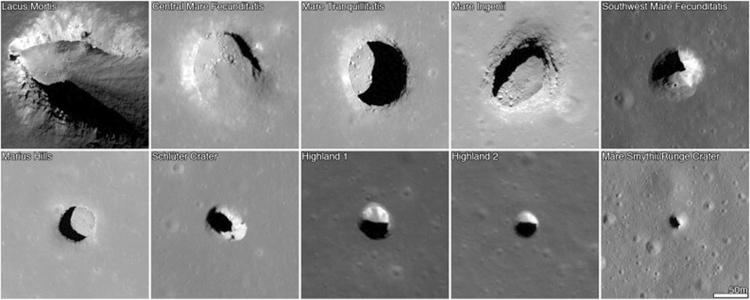
Figure 1. Lunar pits photographed by LROC. The map covers 70
Based on current knowledge about the lava tubes, many have proposed further exploration as the tubes may be able to serve as potential sites for human habitation (Arya et al., 2011; Benaroya, 2017; Daga et al., 1992). With NASA’s Artemis program fully in motion, there has been a stronger push to explore areas on the Moon that could serve as sites for long-term base camps. The first Artemis base camp is planned to be located at the lunar South Pole due to the thorough mapping of the location by orbiters. The South Pole also has regions that are exposed to sunlight at all times, as well as craters and other topographic features that can create permanently shadowed regions containing water ice (Dunbar, 2019). Although there is currently no evidence of water sources in the Marius Hills where the majority of known lava tubes are concentrated, the lava tubes in this region offer other advantages for future base camps. Being underground environments, the lava tubes provide natural protection from solar radiation, surface impacts, and the extreme temperatures of the lunar surface (Angelis et al., 2002). The interiors of the lava tubes will mostly be protected from the dusty conditions on the surface, which have historically been one of the most challenging aspects of lunar exploration, especially during crewed missions. The walls of the lava tubes are potentially airtight due to how they were formed, and therefore can be easily sealed off at the entrance and pressurized (Benaroya, 2017). In addition to the lava tubes mapped in the Marius Hills and around the equator, LROC was able to locate possible skylights in the Philolaus Crater near the lunar North Pole (Lee, 2018). As the Moon’s poles maintain a much lower temperature of about −250
Although there is a database of knowledge on lunar lava tubes, there has yet to be a dedicated mission to explore them. Much of the existing information, including size, temperature, and radiation levels, is based on estimations, and the topology of the tubes is completely unknown. Many of these tubes could also have insufficient roof thickness, and may be prone to collapsing as a result of surface impacts or seismic activity. A robotic mission dedicated to surveying the interior of these lava tubes would help determine whether the tubes are structurally stable and practical for human habitation. This type of mission could also provide more insight into the formation of the Moon and reveal natural resources that may exist underground.
This paper outlines the design and feasibility for an Autonomous Surveying Vehicle (ASV) that could conduct an initial survey of lunar lava tubes (Jagdish, 2024). This ASV will consist of a cold gas propulsion system that will allow it to hover and quickly traverse the lava tubes. The feasibility of this cold gas-propelled vehicle is shown through mathematical simulations, as well as a hardware-in-the-loop simulation of a cold gas thruster. The paper is organized as follows: Section 2 reviews some related research and previously proposed robotic missions to explore lunar lava tubes. Section 3 outlines the high-level ASV mission concept, as well as the basic technical and science requirements for the vehicle. Section 4 describes the prototyping and testing procedures and results for the vehicle. Section 5 contains calculations and simulations that make recommendations for the design of the final vehicle. Finally, Section 6 makes conclusions on the work done in this paper and makes suggestions for future work.
2 Related research
There have been multiple proposals of robotic missions to explore the lunar lava tubes. The Moon Diver mission, a project by NASA Jet Propulsion Laboratory (JPL), suggested using the two-wheeled Axel rover to survey pits in Mare Tranquillitatis (Kerber et al., 2019; Matthews and Nesnas, 2012). This vehicle is designed to traverse rough terrain and is equipped with an infrared sensor, sample drilling and scooping device, inertial measurement unit (IMU), and stereoscopic cameras. Axel also has a central module that it remains tethered to as it descends into the lava tube, with which the rover has the capability to autonomously dock after completing its mission. The tether allows for straightforward navigation back to the central module and provides power to the rover. The rover’s target mass is estimated to be 30 kg. Although the Axel rover’s large wheel diameter of approximately 0.8 m allows it to traverse over certain obstacles, this may prevent the vehicle from exploring smaller areas in the lava tubes (Matthews and Nesnas, 2012). Another project, DAEDALUS, developed under the European Space Agency (ESA), proposes a transparent, spherical vehicle with wheels to traverse the lava tubes. DAEDALUS is a much smaller on-ground vehicle, approximately 0.5 m in diameter and weighing 25 kg. Similar to Moon Diver, DAEDALUS has a central module to which it is tethered. The tether is used for powering the vehicle, as well as data communication and as a wireless access point. Once descended, the vehicle disconnects from the cable and uses wireless communication to relay data as it moves through the tubes. DAEDALUS has on-board LiDAR and panoramic cameras, which are the primary sensors used for its autonomous navigation algorithm (Rossi et al., 2021).
Other designs for vehicles have also been proposed, such as SphereX, which is a spherical hopper vehicle. SphereX contains a solid rocket motor for its propellant, which is used to perform ballistic hops for mobility through the tubes. Each hopper module is only 4 kg and 0.3 m in diameter, making the design viable for a multi-robotic mission (Kalita et al., 2022). Each module has LiDAR, a camera, and other sensors to aid with its autonomous mapping and navigation system. SphereX also uses reaction wheels for its attitude determination and control subsystem. Once the hopper is able to collect sufficient data and begins to run low on power, it will autonomously return to its central module to recharge. Although the hopping operation requires much more power than a wheeled vehicle, SphereX has the advantage of being able to much more easily traverse rough terrain and minimize risk of immobilization (Kalita et al., 2022).
In 2019, the Search for Extraterrestrial Intelligence (SETI) Institute and Astrobotic Technology launched a project to explore lava tubes on Earth using a drone to prepare for similar missions on the Moon and Mars. Although a rotorcraft design is not applicable for exploring lunar environments, the investigation of the Lofthellir Lava Tube Ice Cave in Iceland demonstrated using a LiDAR-equipped vehicle to autonomously navigate and map the interior of the lava tube within minutes (Lee et al., 2019). As the Lofthellir Lava Tube contains huge ice deposits, the mission also aimed to gather geological and environmental data that might give insight into the possible formation of underground water sources on the Moon and Mars.
The main challenge that comes with exploring the lava tubes is the unknown underground environment. The surveying vehicle will need a way to communicate with a central module. Data can either be communicated wirelessly as it is collected, requiring constant line-of-sight with the vehicle, or the vehicle should be able to return to the central module and offload data. Another challenge of exploring the Moon is the necessity of dust protection. Most of these challenges have been thoroughly researched and solved by previous lunar missions, but the unknown terrain presents the greatest obstacle for exploratory vehicles.
The main disadvantage of on-ground vehicles is that they are limited in terms of mobility and may get stuck on rough terrain. Although the Axel rover may be able to navigate over obstacles with its sizeable wheel diameter, smaller on-ground vehicles like DAEDALUS run a much higher risk of being immobilized. Hoppers like SphereX provide a better alternative, they still run the risk of being immobilized because they do not have full directional mobility. Large on-ground vehicles may also hold more space for on-board science payloads, like drills and sample collection mechanisms. These payloads could provide better insight into the geology of the lava tubes, but the overall mission objective should focus on determining the habitability of lava tubes with simple sensors. On-ground vehicles also limit sensing abilities to a short range and make mapping less comprehensive, especially in lava tubes where the roof may be several meters above the vehicle. Additionally, Axel and DAEDALUS’s tethers to their central modules further limit their mobility and the distance they can explore. Although an aerial vehicle with rotors would be ideal, the Moon effectively does not have an atmosphere, eliminating the rotorcraft design as an option. Compared to the currently proposed projects, a vehicle with a compact, self-contained propulsion system that allows for complete mobility would be a lower risk and inexpensive option for an initial survey compared to an on-ground vehicle that could easily get trapped in the terrain.
Although similar drone-like vehicles have been proposed, this paper introduces a novel and lower mass vehicle design utilizing cold gas thrusters, rather than chemical propellants in order to preserve the natural conditions of the lava tubes (Kong et al., 2023; Pescaglia et al., 2022; Tonasso et al., 2024). The vehicle will have full autonomous control and mobility, while wheeled and tethered systems are prone to entanglement, unable to free themselves from rough terrain, and are limited to the length of their tether. On-ground vehicles like Axel and DAEDALUS are also limited to targets on the ground, and cannot traverse crevices and ledges. Hopper vehicles have more capabilities in terms of mobility, but have very limited aerial control. SphereX is fully spherical, which further limits its mobility since the terrain may cause it to roll around or get stuck in a suboptimal orientation. Additionally, SphereX uses combustion to produce thrust, which can disturb the conditions of the lava tubes. The vehicle proposed in this paper will use inert gas at low pressures, which not only protects the insides of the lava tubes, but also makes it safe for humans to be around. Although the proposed vehicle will be too small to hold additional instruments and robotic payloads, the objective of this mission is to quickly retrieve reconnaissance information of these unexplored lunar environments. The data collected on these short surveying missions will be enough to promptly determine whether the region is worth additional investigation with more capable systems, and also to characterize the habitability of the lava tubes.
3 System overview
The ASV will use an integrated propulsion system to simultaneously travel through and map lunar lava tubes using its on-board sensing. The autonomous component of the vehicle will include features such as navigation, mapping, docking, recharging, and data transferral. The ASV will have an advantage over on-ground vehicles as its propulsion system will allow it to efficiently move past any obstacles in the lava tubes. The small size and low mass of the ASV makes it much less expensive to send to the Moon as a payload, compared to on-ground vehicles that are designed to be much larger in order to get over rough terrain, and are also more at risk of being immobilized. In addition, the cold-gas propulsion will use an inert gas to minimize impact on the environment, and combined with its low pressure, be safe to operate around humans. Due to its compactness, the ASV will be a suitable candidate for a multi-robotic system to operate in collaboration to quickly survey and map the lava tubes. The data that will be gathered by the ASV will provide basic initial data on the lava tubes to help determine whether more exhaustive exploration is warranted.
Table 1 shows the technical goals and requirements for the ASV. Since it will not have communication with any devices that may be located above ground, the ASV must be fully autonomous. Since one of the main purposes of the vehicle is to map candidate lava tubes, it will likely use Simultaneous Localization and Mapping (SLAM) for its mapping and navigation operations. SLAM requires the vehicle to be equipped with inertial sensors, such as an IMU, for attitude and angular rate determination. The vehicle will also require an imager for obstacle detection and mapping; since there will be no light inside the lava tubes, a LiDAR or radar will be used for generating a point cloud map. The vehicle will use a microprocessor to autonomously control the propulsion system for navigation. Another mission requirement is to leave the lava tube uncontaminated, as to not disturb natural resources, such as water ice, that may exist underground. In order to meet this requirement, the vehicle will use cold gas as its propellant. Since cold gas will provide a shorter burn time compared to chemical propellants, the ASV must be able to quickly and efficiently traverse the lava tube and have a flight time of at least 3 min. The vehicle should have the ability to travel 30 m in 1 min on the horizontal plane, allowing it to survey lava tubes of sufficient size for a potential habitation module. The wet mass of the vehicle should target a mass of under 10 kg, but should be optimized in order to maximize the burn time. Although cold gas will only allow for a short burn time, the ASV will be able to explore and map much more quickly and efficiently than an on-ground vehicle. The vehicle’s short flight time also prevents the inertial sensors from accumulation of bias and drift, simplifying the attitude and position determination process. The ASV should be able to conduct multiple surveying missions, and therefore must be reusable. The vehicle will be designed with an on-board propellant reserve that can be refilled after each survey flight, as well as a rechargeable power source. Lastly, the vehicle should be able to store and transmit the data gathered during its survey. To achieve this, the vehicle’s microprocessor will need to store and transmit data. Additionally, the microprocessor should have the ability to wireless transmit data in the case of failure to dock with the central module.

Table 1. Mission technical goals and requirements.
The overall science objective is to gather data on lunar lava tubes to determine whether they can be used as sites for lunar base camps. The most important goal is to assess the safety of the tube required for humans by getting data on the structural integrity and the radiation levels. LiDAR or radar imagery can be used to create a comprehensive map of the interior of the lava tube, as well as the surface surrounding the entrance. This map can be merged to calculate the roof thickness of the lava tube and determine its robustness. The lava tubes should also be surveyed for practicality as a human habitat. The composition of the interior atmosphere should be examined for any toxic substances, as well as the amount of lunar dust present and the temperature range inside the tubes. The most important decider of practicality of a lava tube will be access to a water source, whether the tube itself contains an ice deposit or one is available nearby. Lastly, the interior of the tube should be mapped and documented to show what the inside of the tube looks like and how much space is available for a potential base camp. Table 2 outlines the sensing requirements based on the science goals.
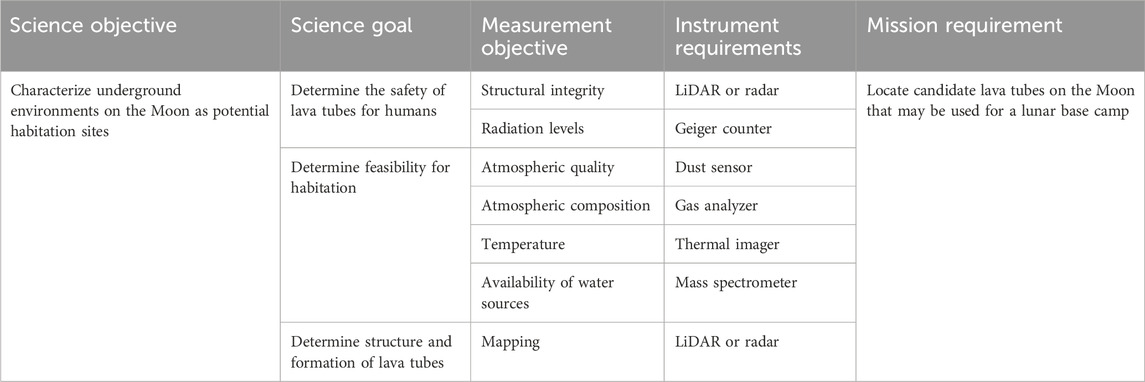
Table 2. Mission science goals and requirements.
Prior to the mission, candidate lava tubes should be identified for the ASV to survey. These candidate tubes should be uncollapsed, and at least 30 m in diameter and length to provide sufficient space for a habitat module. The tubes should also be selected based on feasibility for habitation, considering areas such as permanently shadowed regions that have or are likely to have access to water. Figure 2 shows the proposed concept of operations for a representative surveying mission. For each selected candidate lava tube, (1) the central module (i.e., an astronaut or rover), will stop at the edge of the entrance, (2) where the ASV will descend into the tube. After the descent, the ASV will travel through the lava tube, (3) periodically landing to map and gather sensor data in different areas of the tube. Although the ASV should be able to simultaneously map the lava tube and hover, landing operations may be necessary to gather environmental data, such as regolith samples. Once (4) the ASV has gone below a certain threshold of propellant, (5) it will travel back to the tube entrance and make its ascent onto the central module. After redocking to the central module, the ASV will transmit all of the data gathered, while refilling propellant and recharging its power. The data will be post-processed separately, conceivably on-site, while the ASV will either survey different areas of the same lava tube, or will be taken to the entrance of a new tube.
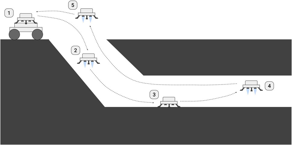
Figure 2. Proposed concept of operations for each short-duration surveying mission.
The goal of this project was to investigate whether the ASV concept is a viable solution to conduct an initial survey of lunar lava tubes, outline the goals and requirements of the mission, and begin the design process for the cold gas propulsion system. Through testing, the design and control of a single thruster was verified to provide enough thrust to satisfy the requirements for vertical motion and hovering. Along with the hardware design and testing done for the propulsion system, simulations were created to demonstrate the mobility of the vehicle with different thruster configurations. The ASV can be broken down into three major subsystems that together provide full maneuverability for the vehicle: propulsion, electronics, and control. The autonomous mapping and navigation implementation were beyond the scope of this project, but SLAM algorithms are well researched and can be applied for the real-time guidance and mapping of the ASV (Yang et al., 2018). Eventually, the final ASV will be a fully autonomous, space-rated system that will be proposed as an inexpensive and low-risk alternative to grounded surveying vehicles for exploring lunar lava tubes.
4 Prototyping and testing
4.1 Nozzle design
This first test aimed to verify that nozzles could be designed to use pressurize cold gas to produce thrust. For testing purposes, this project exclusively used a dry-air compressor due to its accessibility and unlimited flow of gas. The nozzles were designed based on the required thrust, selected gas, stagnation pressure, and number of expected thrusters. Since not all of the components were selected, the total mass of the ASV was assumed to be 2.268 kg (5 lbs) for the first iteration of nozzle designs, which were configured to provide purely vertical thrust with enough magnitude to overcome the mass of the vehicle and hover in place. This mass was selected as a realistic minimum wet mass that would satisfy the mission requirements. The calculations were done assuming air as the gas, noting that the values would be different if an alternate cold-gas propellant were used. In order to maximize thrust, the stagnation pressure at the inlet of the nozzle should be maximized. Due to most solenoid valves having a low pressure threshold and the maximum pressure of the air compressor, the stagnation pressure
The temperature and pressure ratios at the exit were calculated using the Mach number
The effective exhaust velocity
Lastly, the nozzle throat radius
The nozzle design process was done with the assumption that the vehicle would have four independently controlled thrusters. For a vehicle mass of 2.268 kg, the total required thrust on Earth would be 22.24 N. With 5.560 N of thrust required through each thruster, the nozzle throat and outlet radii were 0.15 cm and 0.18 cm, respectively. These calculations represent the ideal thrust through each nozzle and assume no disturbances, such as pressure or temperature loss, that may reduce the thrust. With these dimensions, the nozzle was modeled in SOLIDWORKS as cylindrical nozzles. After testing, the nozzle design was iterated upon with different designs, such as with bell or conical profiles or with varying lengths. The nozzles were 3D-printed using polyethylene terephthalate glycol (PETG).
4.1.1 Nozzle thrust test
This test aimed to verify the magnitude of thrust produced by the nozzle designs for a four-thruster vehicle, and compare the measured thrust to the expected thrust for each nozzle. The nozzles and accompanying test stand were 3D-printed with PETG, and heat-set inserts were integrated to attach the required fittings and connectors as shown in Figure 3. The air compressor line was connected into the nozzle through the underside of the test stand, producing a downwards thrust vector. The test setup also included a manual on-off ball valve and pressure gauge along the air compressor line. The stand with the mounted nozzle was placed on top of a load cell sensor scale to get an initial estimate on the thrust produced by each nozzle design when the valve was opened at around 689.5 kPa (100 psi), and at the steady-state pressure of about 172.4 kPa (25 psi).
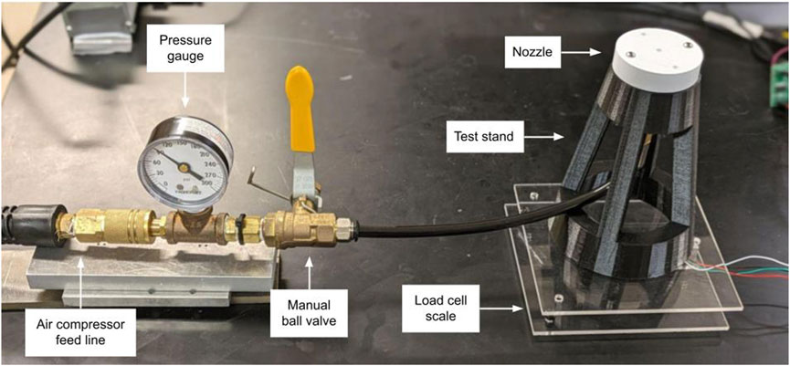
Figure 3. Test stand and load cell scale for nozzle design verification with compressed air.
4.1.2 Nozzle thrust results
Once the nozzles were printed and the inserts were installed, the test described in Section 4.1.1 was done to determine the thrust produced by each nozzle. For these nozzles, the expected thrust at 689.5 kPa (100 psi) was 5.57 N, and the steady-state thrust at 172.4 kPa (25 psi) was expected to be 0.803 N. Although this initial test provided some idea of which nozzle designs were better, the results from the load sensor were not fully accurate as the pressure out of the air compressor immediately started to decrease to 172.4 kPa once the valve was opened.
None of the nozzles met the expected thrust at 689.5 kPa and on average only achieved about 75% of the expected thrust, most likely due to the surface roughness caused by the layer height of the 3D-prints. Nearly all of the nozzles outperformed the expected steady-state thrust at 172.4 kPa. As expected, the nozzles that were either bell-shaped or had fillets, and were shorter in length, performed better than those with sharp internal edges and longer throat-to-exit distances due to lower pressure losses. This suggests that the thrust losses observed in the nozzles are primarily due to surface roughness caused by the printing process and the feed line connectors. The highest performing nozzle was a short bell nozzle, with a maximum thrust of 5.02 N (90.1% of expected) and steady-state thrust of 1.04 N (129% of expected). Based on these values, the Isp of the thruster was approximately 46 s, compared to the 51 s that was expected. Although the air flow through the 3D prints did not result in any leaks, the nozzles were designed for their ideal thrust, not taking in account any disturbances, so it was expected that none of the nozzles would achieve the ideal thrust. Despite the thrust losses through the nozzles, this test verified that some of the designs were able to perform close to the calculated expected thrust and similar nozzle designs could be used on the ASV. The final vehicle will also use an on-board tank, with a pressure regulator between the tank and valve. The regulator will output constant pressure to the nozzles until the tank pressure drops below the output pressure of the regulator. This will allow the thrusters to product steady thrust for the majority of the vehicle’s flight time.
4.2 Component selection
4.2.1 Valve selection
The propulsion system is expected to use solenoid valves to control the propellant flow through the nozzles. The main options for valves are on-off valves and flow adjustment valves. Since the ASV will need the ability to lift off the ground and land softly, an on-off valve would need high-frequency control in order to throttle the thrusters on and off quickly enough to prevent large oscillations. Flow adjustment valves are more suited to this application because their output flow rate can be smoothly controlled with an input signal. For initial testing, a midsize proportional valve from Kelly Pneumatics was selected, which has a response time of 10–15 milliseconds.
This valve allows for smooth, continuous flow out of the nozzle in order to demonstrate vertical thrust control. Its 1/4 in NPT port can be easily integrated with the nozzles, and its maximum pressure of 689.5 kPa is ideal for the air compressor. When fully open at maximum pressure, the valve is expected to have a flow rate of 300 gallons per minute, which is enough to produce the required thrust for testing. Although this valve has a high mass and therefore is not feasible for the final system, demonstrating the control of a thruster using a proportional valve will justify the use of a more compact proportional valve for the final vehicle.
4.2.2 Microprocessor
The primary component of the electronics subsystem is the microprocessor. For testing purposes, the Raspberry Pi Zero 2 W was selected due to its low cost, low mass, and convenient integration with other electrical components. This Raspberry Pi model is 11 g, and its processor runs at 1 GHz. It has a microSD card slot, Bluetooth capabilities, a camera connector, and 40 GPIO header pins. It requires 5 V to power, which can be done with a single 18,650 3.7 V lithium ion battery and a 5 V rechargeable PowerBoost 1,000 charger from Adafruit. The 3.7 V 18,650 battery has a energy consumption of 12.4 Wh, or 6.20 Wh with a 50% depth of discharge. Assuming a minimum flight time of 3 min, the battery would provide 124 W which is more than enough power for all the onboard sensors and actuators. DC power step-up converters can also be used if the battery power is not sufficient, but their main drawback is the reduction of efficiency. Depending on the current requirements of the actuators and due to the short flight time, a DC converter may be able to provide adequate power to the rest of the ASV components.
Raspberry Pis have been used for space applications, such as on-board flight computers for satellite missions. Although it is not rated for lunar environments, the Raspberry Pi has the same features and functionality of a microprocessor that would be appropriate for the final vehicle. Due to the dusty lunar environment, dust protection will be necessary for the microprocessor, along with all the sensors and actuators. The lack of atmosphere on the Moon also creates a need for thermal management with an active cooling mechanism. For the final vehicle, the processing power required for the SLAM algorithm must also be considered in the microprocessor selection. The microprocessor must also have enough storage space to save the 3D point cloud map of the lava tubes.
4.2.3 Sensors and actuators
In addition to the Raspberry Pi, the electronics subsystem will comprise of various sensors to image and map the tubes. Since this project only aimed to verify the ability to provide and adjust vertical thrust, the hardware testing used a single sensor. A VL53L0X time-of-flight distance sensor, with a range of 50–1,200 mm, was used to measure the altitude of the thruster. The proportional valve required a maximum voltage of 12 V provided by an off-board DC power supply. For future testing, power for the actuators should be on-board and supplied directly through the Raspberry Pi with rechargeable batteries and step-up converters. Additional sensing will be required for the final vehicle in order to fulfill the autonomy and science requirements of the mission.
4.3 Thruster prototype
The ability of the thruster to vertically lift and support a hovered mass was tested. This test used a structure of Makerbeam extrusion, with two vertical rails near the center. The rails were inserted through an acrylic plate, onto which the nozzle was mounted. These rails restrict the test platform to only vertical motion, but the holes in the acrylic plate have enough clearance to introduce small orientation disturbances when future tests include attitude control. In this test, the nozzle is facing the bottom of the structure, creating an upwards thrust vector. The nozzle was connected by tubing to the proportional valve and air compressor. A hole was drilled into the Makerbeam extrusion at the top to provide a guide to route the tubing through, and a lightweight aluminum pipe was placed over the tubing in order to minimize friction caused by the tubing. The total mass of the plate, nozzle, tubing, and pipe was also measured to ensure it was below the mass capability of the thruster. Additionally, the VL53L0X distance sensor was placed at the center of the structure directly underneath the nozzle, with a 3D-printed mount to prevent the thruster from impacting the sensor during its landing. Both the valve and sensor were connected to the Raspberry Pi, which used the altitude measurements from the distance sensor to adjust the flow out of the valve and achieve the desired altitude. The circuit used a Texas Instruments SN754410 quadruple half H-bridge driver IC to connect the external 12 V DC power supply to the valve and avoid overloading the Raspberry Pi. The system dynamics from the single thruster model were used for the controller. Figure 4 shows the Makerbeam structure with all of the testing components.
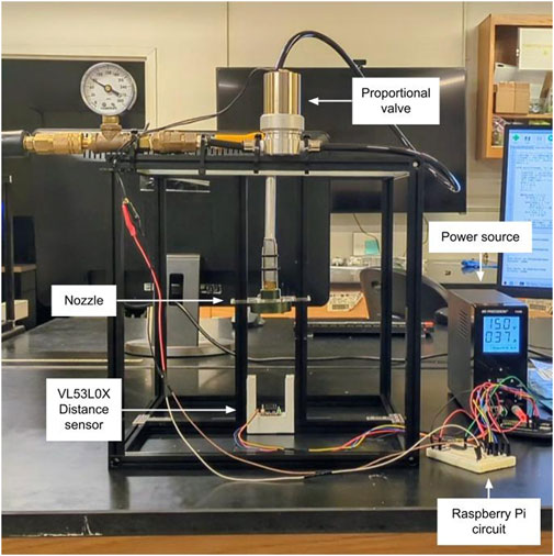
Figure 4. Single-thruster test platform hovering along extrusion rails during testing.
A PID controller was implemented to control the position and velocity of the thruster. Since the control input for this model was the magnitude of thrust, the input was converted into a PWM signal for the Raspberry Pi to regulate the current running through the valve. For calculating the PWM signal, a thrust curve was found by measuring the steady-state thrust at varying input currents, and the data points were curve-fitted to find the required current given the thrust input. The PWM signal corresponded to the percentage of the required thrust out of the maximum possible thrust through the valve. With the controller, the thruster control test aimed to demonstrate the platform starting at rest and hovering to various altitudes before landing. For the first test, the vehicle hovered to 10 cm for 15 s, and then landed. In the next test, the vehicle hovered to 10 cm to 7.5 s, 15 cm for 7.5 s, and then landed. Lastly, the vehicle hovered to 5 cm for 5 s, 10 cm for 5 s, 15 cm for 5 s, and then landed.
4.3.1 Single thruster dynamics
This model describes the dynamics for the vertical motion of a single thruster, and was used to implement a PID controller. These system dynamics assume that the thruster center of mass is aligned with the origin of the coordinate system, that there are no disturbances in the orientation, and that the cold gas supply is off-board such that the mass is constant.
The state vector, x, includes the position
The input, u, is the total thrust
The system dynamics describe the estimation and measurement models. In the following equations, g is the gravitational acceleration of the Earth, and m is the total constant mass of the thruster platform in kg.
Since the thruster test will only be using a distance sensor to determine its vertical positions, the measurement model is as follows.
4.3.2 Thruster control results
The single thruster controller was implemented with the test platform shown in Figure 4. The best performing nozzle from the thrust testing was selected for the hover test. With the valve, the maximum thrust was measured to be about 0.736 N. Once the test stand was assembled, the controller gains were tuned until the platform was able to steadily hover. The proportional, integral, and derivative gains used were 1, 5, and 0.5, respectively. The thrust values were converted to PWM signals using the same linear approximation as the simulation. Figure 5 shows the position of the platform and the control inputs for each of the tests.
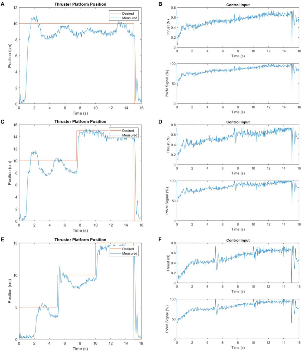
Figure 5. Single-thruster test platform position and control inputs. (A) Position - 10 cm for 15 s. (B) Control inputs - 10 cm for 15 s. (C) Position - 10 cm for 7.5 s, 15 cm for 7.5 s. (D) Control inputs - 10 cm for 7.5 s, 15 cm for 7.5 s. (E) Position - 5 cm for 5 s, 10 cm for 5 s, 15 cm for 5 s. (F) Control inputs - 5 cm for 5 s, 10 cm for 5 s, 15 cm for 5 s.
The platform was able to ascend, hover to each of the desired altitudes, and maintain its position within 3 cm. After 15 s, the platform landed with a short burst of thrust to prevent a hard landing. Overall, the test successfully demonstrated the control of a proportional solenoid valve and cold gas thruster. The plots in Figure 5 show an oscillation in the platform’s position due to the decreasing pressure from the air compressor. Since the system dynamics were derived assuming there were no disturbances to the thrust and did not account for the pressure drop in the compressor, the thrust control input steadily increased over the 15 s to compensate for the pressure loss. With a regulator to maintain a constant pressure and thrust, the thruster should be able to produce the nominally measured thrust for longer time periods. The controller itself can also be improved by tuning the derivative gain to reduce the oscillations in the position of the thruster. Increasing the controller frequency would also improve the thruster control, but this was limited by the valve’s response time of 100 Hz in this prototype test.
5 Vehicle design and simulations
5.1 Propulsion system design
5.1.1 Cold gas selection
One of the main advantages of the ASV is that it will be able to explore while preserving the natural state of the lava tubes by using an inert cold gas as its propellant. Although other propellants, such as hydrazine, have higher specific impulses (Isp), they would require a chemical reaction to occur in the unknown environment of the tubes and contaminate potential water sources. Additionally, liquid propellant would complicate the vehicle control by introducing sloshing dynamics. Table 3 shows cold gas propellants commonly used for space systems, and gases with lower molecular weights will have higher specific impulses.
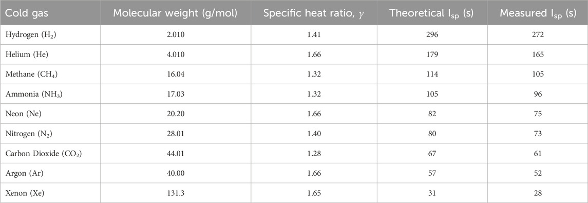
Table 3. Potential cold gas propellants properties at 0
For the final ASV, a cold gas should be selected in order to maximize the burn time. The specific impulse of the selected gas will also be affected by its stagnation temperature and pressure. For testing purposes, this project exclusively used an air compressor due to its accessibility and unlimited flow of gas. No specific impulse data is readily available for air, but since it is comprised of 78% nitrogen, it can be estimated to have similar gas properties as nitrogen with a slightly lower specific impulse.
5.1.2 Cold gas tank
The final vehicle should be integrated with a refillable tank. The tank should be made out of a lightweight material with high tensile strength to minimize the total mass of the tank and maximize the amount of pressurized cold gas that can be held. The gas pressure was assumed to be 2.068 MPa and the temperature to be 293 K. The inner radius of the cylindrical tank was set to 7.5 cm, and the inner height of the tank to 5.5 cm. These dimensions were based on initial estimates but can likely be optimized to minimize mass and maximize pressure capacity in the future. With these dimensions, the internal volume of the tank was 971.93 cm3. In order to calculate the tank masses for each of the potential materials, the hoop stress was calculated with a factor of safety of 1.5 to find the required wall thickness.
Regarding the choice of materials for the primary tank, while aluminum is a natural first option, many alternative materials could be used for a lighter tank. Although plastics are easier for manufacturing with 3D-printing, they would require high mass tanks to contain gas at higher pressures. Metals, such as stainless steel and titanium, would also require heavier tanks. Composite materials would be the most suitable tank material due to their low density and high tensile strength. With a carbon fiber tank, the required wall thickness would be 0.254 cm and the tank dry mass would only be 0.2439 kg. Additionally, carbon fiber could easily be manufactured into a custom tank with wet layups on a mold, or a commercial-off-the-shelf tank could be purchased.
5.1.3 Cold gas burn time
The burn times were calculated for different cold gases, assuming a four-thruster vehicle hovering in place such that the required thrust is equal to the weight of the vehicle. These calculations assumed that the total initial mass of the vehicle was 10 kg and the propellant mass was 2.9 kg. The acceleration due to gravity on Earth is 9.807 m/s2, and the atmospheric pressure is 101.3 kPa. The acceleration due to gravity on the Moon is 1.625 m/s2, and the atmospheric pressure is

Table 4. Calculated burn times for a 10 kg vehicle with 2.9 kg of cold gas on the Earth and Moon.
5.1.4 Propellant mass optimization
The propellant mass of the vehicle can be selected in order to maximize the burn time. This optimization assumes the vehicle has a carbon fiber propellant tank and a structural mass (excluding the tank mass) of 3.5 kg, based on initial part selection. The optimization was performed for four cold gases: hydrogen, helium, nitrogen, and carbon dioxide. Two example tank designs were used for the mass optimization. The first tank (design #1) was a cylindrical tank with 10.0 cm for both the internal radius and height, providing a tank volume of 3,142 cm3. An alternate tank design (design #2) was a spherical tank with an internal radius of 3.0 cm and tank volume of 113 cm3. The tank mass was calculated for different propellant masses, yielding the total mass of the vehicle and the total flight time. Table 5 shows the mass breakdown and burn times with different cold gases for both tank design. With these assumptions, the optimal wet masses are higher for the cylindrical tank design since it requires a higher wall thickness. For nitrogen and carbon dioxide, the optimal mass with a cylindrical tank is also higher than the 10 kg wet mass requirement.
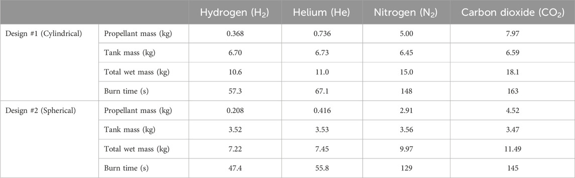
Table 5. Optimized vehicle mass breakdown and burn time with cylindrical and spherical tank designs for lunar flight, assuming a dry mass (excluding tank mass) of 3.5 kg.
Carbon dioxide generally yields the longest burn times since it has a high gas density and therefore can be stored at higher pressures in smaller tanks. For the cylindrical tank design, carbon dioxide provides a total burn time of 163 s and total vehicle wet mass of 18.1 kg. For the spherical tank design, carbon dioxide provides a total burn time of 145 s and total vehicle wet mass of 11.5 kg. A spherical tank with nitrogen allows for a comparable burn time of 129 s and wet mass of 9.97 kg, which complied with the mass requirement for the vehicle, as shown in Figure 6. Although the tank dimensions are not finalized, the spherical tank design allows for minimizing the tank mass and maximizing the burn time. Once all of the hardware is selected and the structural mass excluding the tank is finalized, this same optimization can be performed for different cold gases and tank dimensions to select the optimal propellant mass and tank design for the final vehicle. Nonetheless, this analysis highlights that a system with a total mass under 10 kg can achieve the 3-min flight time of the system requirements, with longer flight times likely possible.

Figure 6. Nitrogen mass and burn time optimization with a spherical tank for lunar flight, assuming a dry mass of 3.5 kg excluding the tank. The optimal propellant and tank masses are 2.91 kg and 3.56 kg, respectively, yielding a burn time of 129 s.
Table 6 outlines a preliminary mass budget for the final vehicle based on the current part selection, targeting a nominal wet mass of 10 kg in accordance with the technical requirements. The cold gas and tank mass correspond to the optimized mass values with nitrogen and a spherical tank design, as shown in Table 5, and the remaining dry mass is approximately 3.5 kg. Each component has a mass margin, which causes the total mass to exceed the 10 kg wet mass requirement. However, it is unlikely that all components will fill their maximum allocation, and some components may be lower than their nominal mass. Additional mass with margin included is also allocated for the structure, remaining sensors, and integration hardware such as fasteners, wires, and feed lines. As component selection is finalized for the final vehicle, this mass budget can be used to redesign the thrusters and calculate the optimal propellant mass and burn time.
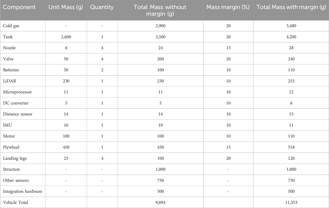
Table 6. Preliminary mass budget for final vehicle with margins.
5.1.5 Subsystem design
A few of the other components that have yet to be incorporated into the propulsion system are pressure regulators, relief valves, and gas filters. For testing, the relief valve may not be required if the inlet pressure is low and gas filters may not be required since the system does not need to be space rated yet, but these two components would help keep feed lines clean, protect other propulsion components, and also provide a failsafe for the pressurized system.
5.2 Vehicle lunar simulations
5.2.1 Vehicle dynamics
In order to assess the viability of different vehicle designs, multiple thruster configurations were considered. The following subsections describe each of the system dynamics that were modeled for various vehicle designs. Each design assumes that the vehicle, which is modeled as a flat cylinder, is symmetrical and rigid, and the center of mass is aligned at the origin of the coordinate system. The dynamics neglects the rotation of the Earth and Moon, fluid and wind effects, and any other external disturbances. The models assume constant gravity for each celestial body (gEarth = 9.807 m/s2 and gMoon = 1.625 m/s2).
5.2.1.1 Multi-thruster, zero pitch and roll
This model (design #1) describes the dynamics for the position, linear velocity, orientation, angular velocity, and mass of a vehicle designed with any number of vertical thrusters (limited here to be either 1, 3, or 4). The thrusters of this vehicle would be configured perpendicular to the xy-plane, and each would provide the same amount of thrust such that the vehicle is unable to pitch or roll, as shown in Figure 7. This design would only require a single valve for vertical thrust since each of the vertical thrust vectors would be equal, as long as the valve is rated for the required flow rate. Directional control along the horizontal plane would be provided by a separate mechanism, such as thrusters normal to the outer diameter of the vehicle along the x and y-axes. Yaw control would be provided by a separate mechanism, such as a thruster tangent to the outer diameter, or a reaction wheel. These system dynamics assume that the mass is variable, but the mass flow rate variable can be set to 0 to represent constant mass with an off-board cold gas supply for testing purposes.

Figure 7. Possible thruster configurations and coordinate frames. (A) Multi-thruster vehicle configuration with four horizontal and four vertical thrusters. (B) Multi-thruster vehicle coordinate frame with position and yaw control. (C) Four-thruster vehicle configuration with four vertical thrusters. (D) Four-thruster vehicle coordinate frame with position and full attitude control.
The state vector, x, describes the orientation, angular velocity, position, linear velocity, and mass of the vehicle. The orientation is in rad, represented by the roll
The input, u, is defined by the respective thrusts along the x and y-axes
The equations of motion are described by the system dynamics. In the following equations,
The moments of inertia about the x, y, and z-axes
5.2.1.2 Four-thruster design
This model (design #2) describes the dynamics for the position, linear velocity, orientation, angular velocity, and mass of a vehicle designed with four thrusters with equal spacing. The model assumes that the yaw, or rotation about the z-axis, is 0
The state vector is the same as the multi-thruster states of design #1. The input, u, is defined by the total vertical thrust produced by the thrusters
The equations of motion are described by the system dynamics. In the following equations,
5.2.2 Lunar simulations
The vehicle system dynamics described in Section 5.2.1 were simulated using MATLAB and controlled with PID controllers for a lunar environment in order to evaluate and compare the propellant usage for both scenarios to select a thruster configuration for the final vehicle. For these simulations, the total initial mass of the vehicle was 10 kg, the propellant mass was 2.9 kg, and the propellant used was nitrogen, based on the mass budget in Table 6. Both simulations also assume a non-constant mass, updating the vehicle’s mass and moments of inertia at each time step. The vehicle started at rest at the origin, and had a desired altitude of 10 m, and desired range of 30 m in both the x and y directions. Once converging to within 2% of its desired position, the vehicle was simulated to perform a controlled, soft landing. The goal of the simulation was to demonstrate the vehicle being able to hover and travel into a hypothetical lava tube, and use less than 50% of its total propellant.
5.2.3 Vehicle design evaluation
Design #1 (described in Section 5.2.1.1) uses vertical thrusters for altitude control, as well as separate horizontal thrusters for range control. In this configuration, the vehicle maintains a pitch and roll of zero, making the controller much simpler as each axis has a separate thruster. For the lunar simulation, all the Euler angles and body angular rates were zero. The maximum vertical thrust was assumed to be two times the weight of the vehicle, and the maximum horizontal thrust was assumed to be half the weight of the vehicle. These values were chosen based on what would be realistic in lunar gravity. The final vehicle’s maximum thrust in each direction will be dependent on the selected cold gas and specific impulse. Both designs were assumed to have the same wet and dry mass, so the mass of the additional thrusters required for this design was not taken into consideration.
Design #2 (described in Section 5.2.1.2) uses only vertical thrusters for its altitude, attitude, and range control. In this configuration, the vehicle will pitch and roll in order to create horizontal thrust components. Each thruster will be controlled separately in order to achieve and maintain the correct attitude angles. The maximum vertical thrust was assumed to be two times the weight of the vehicle. For the lunar simulation, the initial pitch and roll were set to 0.023 rad and the states were directly adjusted to achieve approximately the same trajectory as Design #1 rather than using a controller.
Using the same mass breakdowns for both vehicle simulations and similar trajectories, the propellant usages were compared. Both vehicles take approximately 45 s to fully ascend and converge to the desired position, and about 4 s to descend and land. The multi-thruster vehicle (Design #1) simulation shows that 34.4% of the propellant was used, while the four-thruster vehicle (Design #2) used 31.9% of the propellant for the same trajectory.
With the previous propellant and structural mass assumptions, the four-thruster vehicle design would be able to ascend up to 4,070 m in 53 s or translate 1830 m with a pitch angle of 0.1 rad over 150 s before running out of propellant, as shown in Figure 8. The maximum translation distance confirms that the vehicle will be able to traverse well over the 30 m required by the mission technical goals.
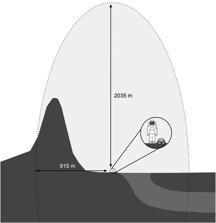
Figure 8. Mission concept demonstrating maximum two-way range of vehicle. The two-way horizontal range is expected to be 915 m, and the two-way vertical range is expected to be 2035 m.
5.3 Vehicle design concept
Due to the lower propellant usage of Design #2 and the simplicity of the design, it was concluded that the final vehicle should only use vertical thrusters to control both the orientation and position of the vehicle, rather than incorporating separate thrusters for horizontal control. Although the lunar simulations were done assuming four total thrusters on the vehicle, further optimization can be done for the total number of thrusters depending on the amount of hardware and mass budget required for each thruster. All component selection for the final vehicle should be done according to the mission requirements, but also to minimize the total mass of the vehicle.
Figure 9 shows a design concept for the final lunar vehicle, assuming a four-thruster design. The final vehicle will have a custom cold gas tank in the center, most likely made of carbon fiber. It should also have landing legs to prevent the bottom of the tank from being punctured upon landing. A DC motor at the center of the vehicle is attached to a flywheel for yaw control. The flywheel can be 3D-printed and use a weighted, metal outer rim to increase its moment of inertia and provide motion stability. The vehicle should also feature some type of cover to protect the sensors and actuators from lunar dust. The LiDAR is mounted at the top of the vehicle to allow for full visibility of its surroundings.

Figure 9. Final vehicle design concept with four vertical thrusters and a carbon fiber cold gas tank. The design shows the landing legs, a shell for dust protection, LiDAR and other sensors, and a flywheel for yaw control.
6 Conclusion
The goal of this study was to demonstrate the viability of a vehicle with an on-board propulsion system to survey lunar lava tubes and other features of interest on the Moon. The vehicle’s novel design, featuring a self-contained and refillable cold gas propulsion system, allows it to conduct multiple short-term surveying missions of the lava tubes. Through the prototyping and testing of a single thruster, and simulations to determine the design of the final vehicle, the ASV has been shown to satisfy the criteria established for performing these initial surveys of lava tubes. Although this project has outlined the mission concept and begun the development of the mission and vehicle design, many of the details and components are left to future work.
From the nozzle thrust testing, the reduced thrust at 689.5 kPa may be due to pressure losses in the nozzle itself, especially through the tubing and fittings in the feed line. In the future, other manufacturing methods, such as resin printing or metal machining, may be used for a smoother surface finish on the nozzles. The temperature of the compressed air may also be lower than the 300 K assumed in the calculations. Since the nozzles performed well at the steady-state pressure, it is possible that the load cell sensor used for testing does not have a high enough response time to accurately measure the thrust before the pressure from the compressor begins to decrease, so a higher frequency sensor could help provide a more accurate measure of the thrust at the maximum pressure. A pressure regulator would also aid in this by supplying a constant flow at the maximum pressure required by the nozzles.
Additionally, the lunar burn time calculations in Table 4 show that about one-tenth of the mass flow rate and stagnation pressure are required compared to the same design on Earth, so hardware with lower maximum pressures can be used for the propulsion system as long as the pressure regulator has the ability to reduce the tank pressure enough. Since the required pressure is lower, the final lunar vehicle will be able to use a low-pressure, miniature proportional valve, which would typically be much lighter and more compact than the hardware required for a similar propulsion system on Earth.
Through this research, the technical goals and objectives of the mission from Table 1 were found to be feasible. The lunar simulations show that the vehicle will be able to travel more than the required 30 m in 60 s, verifying the proposed length of each surveying mission. The propellant mass optimization and preliminary mass budget show that the hardware for the vehicle is expected to target 10 kg wet mass limit, although some margin is allocated for uncertainty of the final component selection. The propulsion system must still be further developed, but preliminary nozzle testing and thruster control demonstrate that the vehicle position and attitude can be controlled with a proportional solenoid valve. The LiDAR-based SLAM algorithm will also be a significant challenge in the vehicle’s development.
As a low-mass and inexpensive alternative to on-ground exploratory vehicles, the ASV will be able to efficiently collect environmental data to help evaluate the safety and practicality of lava tubes as habitation sites. Although designed with the intention of surveying underground environments, the ASV can also be convenient for other situations, such as exploring hazardous or inaccessible areas of the lunar surface, or even high-altitude locations on Mars. This research shall provide the grounds for further development of such a vehicle to be proposed for future lunar missions as the first to explore the interiors of lunar lava tubes.
Data availability statement
The raw data supporting the conclusions of this article will be made available by the authors, without undue reservation.
Author contributions
NJ: Conceptualization, Investigation, Methodology, Software, Visualization, Writing – original draft, Writing – review and editing. BG: Conceptualization, Resources, Supervision, Writing – review and editing.
Funding
The author(s) declare that no financial support was received for the research and/or publication of this article.
Acknowledgments
The authors thank Dr. Christopher Carr and Dr. Glenn Lightsey for their expertise and feedback. This study is based upon the work done for a Master’s thesis (Jagdish, 2024).
Conflict of interest
The authors declare that the research was conducted in the absence of any commercial or financial relationships that could be construed as a potential conflict of interest.
Generative AI statement
The author(s) declare that no Generative AI was used in the creation of this manuscript.
Publisher’s note
All claims expressed in this article are solely those of the authors and do not necessarily represent those of their affiliated organizations, or those of the publisher, the editors and the reviewers. Any product that may be evaluated in this article, or claim that may be made by its manufacturer, is not guaranteed or endorsed by the publisher.
References
Angelis, G. D., Wilson, J. W., Clowdsley, M. S., Nealy, J. E., Humes, D. H., and Clem, J. M. (2002). Lunar lava tube radiation safety analysis. J. Radiat. Res. 43, S41–S45. doi:10.1269/jrr.43.S41
Arya, A. S., Rajasekhar, R. P., Thangjam, G., and Kumar, A. S. K. (2011). Detection of potential site for future human habitability on the Moon using Chandrayaan-1 data. Curr. Sci. 100.
Bart, G. D., Nickerson, R. D., Lawder, M. T., and Melosh, H. J. (2011). Global survey of lunar regolith depths from LROC images. Icarus 215, 485–490. doi:10.1016/j.icarus.2011.07.017
Benaroya, H. (2017). Lunar habitats: a brief overview of issues and concepts. REACH 7–8, 14–33. doi:10.1016/j.reach.2018.08.00208.002
Blair, D. M., Chappaz, L., Sood, R., Milbury, C., Bobet, A., Melosh, H. J., et al. (2017). The structural stability of lunar lava tubes. Icarus 282, 47–55. doi:10.1016/j.icarus.2016.10.008
Bowman, A. (2024). Artemis III. NASA. Available online at: https://www.nasa.gov/mission/artemis-iii/
Daga, A. W., Daga, M. A., and Wendel, W. R. (1992). “Evolving concepts of lunar architecture: the potential of subselene development,” in 2nd conference on lunar bases and space activities.
Dunbar, B. (2019). Moon’s South Pole in NASA’s landing sites. NASA. Available online at: http://www.nasa.gov/feature/moon-s-south-pole-in-nasa-s-landing-sites
Greeley, R. (1971). Lava tubes and channels in the lunar Marius Hills. Moon 3, 289–314. doi:10.1007/BF00561842
Haruyama, J., Hioki, K., Shirao, M., Morota, T., Hiesinger, H., van der Bogert, C., et al. (2009). Possible lunar lava tube skylight observed by SELENE cameras. Geophys. Res. Lett. 36. doi:10.1029/2009GL040635
Jagdish, N. (2024). Development of an autonomous surveying vehicle for underground lunar environments. Georgia Institute of Technology. Master’s thesis. Available online at: https://repository.gatech.edu/entities/publication/b7929ed4-7f63-47d0-853a-e48a6fee3503
Kalita, H., Diaz-Flores, A., and Thangavelautham, J. (2022). Integrated power and propulsion system optimization for a planetary-hopping robot. Aerospace 9, 457. doi:10.3390/aerospace9080457
Kerber, L., Denevi, B. W., Nesnas, I., Keszthelyi, L., Head, J. W., Pieters, C., et al. (2019). “Moon Diver: a discovery mission concept for understanding secondary crust formation through the exploration of a lunar mare pit cross-section,” in Lunar and planetary science conference.
Kong, C.-W., Lo, M., Gamba, M., and Santangelo, G. (2023). Conceptual design of a lunar drone operated using in-situ propellant. American Institute of Aeronautics and Astronautics. ASCEND. doi:10.2514/6.2023-4762
Lee, P. (2018). “Possible lava tube skylights near the North Pole of the Moon,” in Lunar and planetary science conference.
Lee, P., Kommedal, E., Horchler, A., Amoroso, E., Snyder, K., and Birgisson, A. F. (2019). “Lofthellir Lava Tube Ice Cave, Iceland: subsurface micro-glaciers, rockfalls, droner LiDAR 3D-mapping, and implications for the exploration of potential ice-rich lava tubes on the Moon and Mars,” in Lunar and planetary science conference.
Matthews, J. B., and Nesnas, I. A. (2012). “On the design of the Axel and DuAxel rovers for extreme terrain exploration,” in 2012 IEEE Aerospace conference, 1–10. doi:10.1109/AERO.2012.6187039
Nguyen, H., Köhler, J., and Stenmark, L. (2002). The merits of cold gas micropropulsion in state-of-the-art space missions. American Institute of Aeronautics and Astronautics.
Pescaglia, S., Bortolato, G., Maggiore, P., and Messidoro, P. (2022). “Lunadrone: small autonomous spacecraft for lunar lava tubes exploration,” in 2022 IEEE 9th international workshop on metrology for AeroSpace (MetroAeroSpace), 612–617. doi:10.1109/MetroAeroSpace54187.2022.9856057
Rossi, A. P., Maurelli, F., Unnithan, V., Dreger, H., Mathewos, K., Pradhan, N., et al. (2021). DAEDALUS - descent and exploration in deep autonomy of lava underground structures
Terenzi, A. (2022). “Steady compressible flow,”. Gulf Professional Publishing. doi:10.1016/B978-0-12-822466-3.00002-3
Tonasso, R., Tataru, D., Rauch, H., Pozsgay, V., Pfeiffer, T., Uythoven, E., et al. (2024). A lunar reconnaissance drone for cooperative exploration and high-resolution mapping of extreme locations. Acta Astronaut. 218, 1–17. doi:10.1016/j.actaastro.2024.02.006actaastro.2024.02.006
Keywords: lunar exploration, autonomous vehicles, cold gas propulsion, lava tubes, reusable propulsion system
Citation: Jagdish N and Gunter BC (2025) Feasibility study of a cold gas-propelled autonomous surveying vehicle for lunar environments. Front. Space Technol. 6:1534477. doi: 10.3389/frspt.2025.1534477
Received: 26 November 2024; Accepted: 26 May 2025;
Published: 13 June 2025.
Edited by:
Serdar Sean Kalaycioglu, Toronto Metropolitan University, CanadaReviewed by:
Bryan Palaszewski, National Aeronautics and Space Administration, United StatesYe Lu, Worcester Polytechnic Institute, United States
Philip Arm, ETH Zürich, Switzerland
Copyright © 2025 Jagdish and Gunter. This is an open-access article distributed under the terms of the Creative Commons Attribution License (CC BY). The use, distribution or reproduction in other forums is permitted, provided the original author(s) and the copyright owner(s) are credited and that the original publication in this journal is cited, in accordance with accepted academic practice. No use, distribution or reproduction is permitted which does not comply with these terms.
*Correspondence: Brian C. Gunter, YnJpYW4uZ3VudGVyQGFlcm9zcGFjZS5nYXRlY2guZWR1