 G. G. Jang
 Y. Zhang
 J. K. Keum2,3
 D. Jassby
 C. Tsouris
- 1Manufacturing Science Division, Oak Ridge National Laboratory (ORNL), Oak Ridge, TN, United States
- 2Neutron Scattering Division, ORNL, Oak Ridge, TN, United States
- 3Center for Nanophase Materials Science and Neutron Scattering Division, Oak Ridge National Laboratory, Oak Ridge, TN, United States
- 4George W. Woodruff School of Mechanical Engineering, Georgia Institute of Technology, Atlanta, GA, United States
- 5Department of Civil and Environmental Engineering, Institute of the Environment & Sustainability and California NanoSystems Institute, University of California, Los Angeles, Los Angeles, CA, United States
In this work, neutron computed tomography (CT) is employed to investigate the dissolution of porous aluminum electrodes during electrocoagulation (EC). Porous electrodes were chosen in efforts to reduce electric power requirements by using larger surface-area electrodes, having both inner and outer surface, for the EC process. Neutron CT allowed 3D reconstruction of the porous electrodes, and image analysis provided the volume of each electrode vs. thickness, which can indicate whether the inner surface is effectively involved in EC reactions. For the anode, the volume decreased uniformly throughout the thickness of the electrode, indicating that both the outer and inner surface participated in electrochemical dissolution, while the volume of the cathode increased uniformly vs. thickness, indicating deposition of material on both the outer and inner surface. The attenuation coefficient vs. thickness, increased for both anode and cathode, indicating surface chemistry changes. For the anode, the attenuation coefficient increased slightly but uniformly, probably due to aluminum oxide formation on the surface of the anode. For the cathode, the attenuation coefficient increased more than for the anode and nonuniformly. The higher increase in the attenuation coefficient for the cathode is due to precipitation of aluminum hydroxide on the electrode surface, which added hydrogen. Image analysis also showed that, although the attenuation coefficient increased throughout the thickness of the electrode, most of the hydroxide deposition occurred on the outer surface. Energy analysis showed that porous electrodes can be used to reduce process energy requirements by as much as 4 times compared to solid electrodes.
Introduction
In efforts to develop high-performance electrode materials over the past 2 decades, integrated one-dimensional (1D: nanowires, nanoribbons, nanotubes), two-dimensional (2D: nanosheets, nanoplates, nanomembranes), and three-dimensional (3D) architectures were introduced in electrode materials (Liu et al., 2019). 1D and 2D nanostructured electrodes still suffer from severe aggregation, which prevents fast diffusion of electrolytes and fast kinetics of electrochemical reactions, thus affecting charge and mass transfer and increasing the process energy requirements (Liu et al., 2019). Most electrochemical reactions in aqueous solutions take place at the interface of the electrode and the electrolyte. Thus, the surface area of the electrodes plays a vital role in determining the efficiency of an electrochemical process, like in any surface reaction (Santhanagopalan and White, 2009).
There are many methods to increase the area for reaction; stacking multiple electrodes and using bipolar electrodes are the most common (Ge et al., 2004; Mohora et al., 2014; Deghles and Kurt, 2016). To further increase the available area for reactions, a 3D porous electrode can be used, thus making the entire thickness of the electrode available for contact with the aqueous solution for the reaction to occur. Since the reaction takes place in the 3D space, it is more distributed than in 2D or 1D electrodes and, thus, the limitations in terms of diffusion and ohmic drop are considerably reduced (Santhanagopalan and White, 2009). Porous electrodes have been used in various applications with aqueous solutions, specifically for storing electrical energy in electrostatic double-layer supercapacitors, capacitive deionization (CDI) for water treatment and desalination, electrochemical water treatment, recovery of metals, organic syntheses, as well as for batteries and fuel cells (Newman and Tobias, 1962; de Levie, 1963; Johnson and Newman, 1971; Soffer and Folman, 1972; Newman and Tiedemann, 1975; Dunn and Newman, 2000; Sun et al., 2012; Hemmatifar et al., 2015; Sharma et al., 2015; Smith and Dmello, 2016; Bao et al., 2018; Liu et al., 2019; Tang et al., 2019). Compared with flat nonporous electrodes, porous electrodes improve the ability of the system to store ions and electrons and increase the charge transfer and reaction rate (Santhanagopalan and White, 2009). The high specific surface area allows high current without a large overpotential and also sustains high current due to lesser chances of passivation at the electrode surface.
Recent technological advancements have increased the complexity of the contaminants in water, thus requiring better and more efficient methods for water treatment (Tsouris et al., 2001; Liu et al., 2022; Magnisali et al., 2022). Electrocoagulation (EC) is one such method which is versatile in treating all kinds of water including groundwater, industrial wastewater, and surface water (López-Guzmán et al., 2021). In EC, aluminum or iron electrodes are used as sacrificial electrodes to generate the coagulant by passing DC current across the electrodes when they are dipped into the solution to be treated. Despite EC being researched for decades, scaleup of the technology is challenging due to deterioration and passivation of electrodes, short-term stability, etc. (Alam et al., 2021) Also, the high capital and operating costs of EC due to the cost of the electrodes and the use of electricity are a deterrent for scaleup (Alam et al., 2021). Thus, research is needed to improve electrode consumption and reduce passivation, both of which can be improved by using porous electrodes.
Computed tomography (CT) is a non-destructive technique that can spatially resolve internal and external structures. X-rays and electrons are two most used tomography probes in many research fields, but they are limited in studying bulk metal objects. Neutrons, as a complementary probe, interact weakly with common metals and strongly with light elements (H, Li, etc.) (Kardjilov et al., 2018). Therefore, neutron computed tomography (nCT) has been used to investigate internal structures and light element distributions in bulk materials (AGENCY, 2008; Kardjilov et al., 2017; Tengattini et al., 2021).
In this paper, porous electrodes are evaluated through neutron tomography to provide a better understanding of the electrode dissolution process of porous aluminum electrodes used for EC. Solid and porous electrodes are compared in terms of energy requirements for aluminum dissolution to test the hypothesis that high-surface-area electrodes may be more energy efficient for EC. One of the questions addressed is whether dissolution occurs uniformly from both the outer and inner surface of the electrodes. If, for example, only the outer surface dissolves during EC, then the benefits of the high-surface-area electrodes may be limited. This question is addressed by combining nCT analysis with material characterization using scanning electron microscopy (SEM) and energy-dispersive X-ray spectroscopy (EDS).
Experimental methods
Materials
Aluminum foam sheet with obturator structure [i.e., ∼5 ppi (pores per inch), 55–60% porosity with open cell, 10-mm thickness, >99% purity; ZOPIN-55%AL] was purchased from the Zopin Group, metal foam manufacturer. Aluminum foam block with open cell (40 ppi, processed from 6101 alloy) was purchased from Duocel. The solid electrode used was aluminum strips from McMaster-Carr, United States.
EC cell operation
Synthetic groundwater solution was prepared with a composition of 0.85 mM Na2SiO3⋅H2O, 1.33 mM HCl, 0.674 mM CaCl2 and 0.27 mM MgCl2, and had an initial pH of 8.5. The electrocoagulation cell was custom-built for two aluminum foam electrodes spaced 1 cm apart. One liter of synthetic groundwater solution was continuously stirred at 400 rpm. Two identical pieces of aluminum foams (7.6-cm diameter, 1.0-cm thickness) were used for the cathode and anode. For Al foam sheet with obturator structure, the electrodes were cut to 7.6-cm diameter with 1.0-cm thickness, while for Al foam with open cell, the electrodes were cut into cylinders of 2.5-cm diameter and 2.5-cm height. The nominal electrode wetted areas for the circular plates and the cylinders are 115 cm2 and 30.3 cm2, respectively. For the solid electrode experiments, two identical aluminum strips were used as the anode and cathode, and the wetted area of the electrodes was matched to that of porous electrodes. A fixed maximum voltage of 32 V was applied to maximize the anode dissolution using a power supply (Siglent Technologies SPD3303X-E). The current was set to 1 A, and current fluctuations were monitored over time.
Porous electrodes may be employed to reduce power requirements for the EC process. The higher surface area of porous electrodes, compared to that of flat electrodes, needs a lower applied potential to yield the same current. Since the power is the product of potential and current, a lower potential for the same current yields proportionally lower electric power. SEM and Energy Dispersive Spectroscopy (EDS) were carried out using a field emission scanning electron microanalyzer (Merlin, Carl Zeiss AG).
Neutron experiment
Neutron computed tomography was conducted using the CG-1D instrument at the High Flux Isotope Reactor (HFIR) of the Oak Ridge National Laboratory (Crow et al., 2011; Santodonato et al., 2015). The instrument was configured to measure at L/D = 600, where L is the distance from the aperture to the detector (6.59 m), and D is the aperture diameter (11 mm). Given the size of available field-of-view (∼8.6 cm × 8.6 cm), four samples of diameter ∼76.2 mm or three samples of diameter ∼25.4 mm were stacked for each CT scan. Quartz plates were used as spacers between aluminum electrodes. In the CT scan, samples were rotated from 0° to 360°, and a 30 s image was collected at every 0.17° increment for the 76.2 mm samples, or 0.42° increment for the 25.4 mm samples. A 100-μm thick 6LiF/ZnS scintillator was used to convert the transmitted neutrons into light, and the light signal was collected using a charge-coupled device (CCD) into a grayscale image. The effective pixel size in this experiment is measured to be ∼42 μm. 3D volume reconstruction was performed using filtered-back-projection in MuhRec. (Kaestner, 2022). 3D visualization and data analysis were performed using Amira, (Stalling et al., 2005), which is developed by Thermo-Fisher Scientific in collaboration with the Zuse Institute Berlin.
Energy calculations
The amount of aluminum dissolved depends on the current applied to the electrode based on Faraday’s law:
where w is the mass of Al dissolved, I is the current (A), t is the time (s), M is the molecular weight of aluminum (27 g/mol), Z is the number of electrons involved in the reaction (3) and F is Faraday’s constant: 96,485.
To calculate the energy required to dissolve aluminum and compare it with the solid electrode, experimental conditions were chosen so that the amount of aluminum dissolved is same for the porous and solid electrodes. This selection would allow us to directly compare the porous electrode and the solid electrode in terms of the energy needed to dissolve a fixed amount of aluminum in the solution.
The energy required for aluminum dissolution (Edis in W-h) was calculated based on the equation below: (López-Guzmán et al., 2021):
where V is the applied voltage (V), I is the current response (A) and t is the time for which the voltage is applied (hours).
Results and discussion
Ex-situ nCT measurements were performed at HFIR to characterize surface changes of porous aluminum (Al) foam electrodes over time during electrocoagulation for groundwater treatment. The EC reactions at the anode and cathode are: (Liu et al., 2022):
The bulk chemical reaction is therefore written as:
Large pore sized aluminum foam
EC experiments were carried out between nCT measurements using a customized electrochemical cell at a fixed voltage of 32 V for two or 4 h (Figure 1).
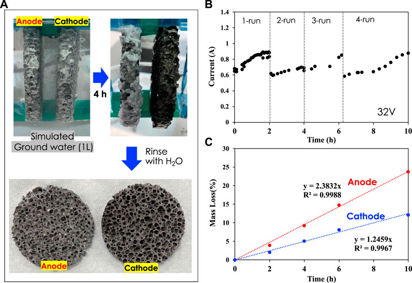
FIGURE 1. (A) Electrocoagulation experiments with porous Al foam electrodes (3-inch diameter) in simulated groundwater; (B) Electrical current vs. time at 32 V; (C) Mass loss of anode and cathode electrodes over time.
Al foam electrodes of 3-inch diameter with five ppi (pores per inch) were used for both anode and cathode. After each run, the electrodes were rinsed with DI water and dried in a vacuum chamber at 80°C prior to nCT scans. The mass of both anode and cathode was measured before CT scans. The experiment shown in Figure 1 was carried out with fresh groundwater solution. Figure 1A shows how the electrodes look after 4 h of EC and after rinsing and drying. The cathode color changed from gray to black due to hydroxide slurry/salt deposition and oxide film formation, while the anode color remained unchanged due to aluminum dissolution. Figure 1B presents the electrical current histories for 32-V applied voltage during runs 1, 2, 3, and 4. Figure 1C shows that the anode was dissolved, resulting in approximately 23 wt% loss after a total of 10-h EC time, while the cathode lost approximately 11 wt% at the same time. The significant mass loss of anode is due to sacrificial dissolution of aluminum into the solution. In parallel, aluminum oxide film formed on the surface of the cathode was continuously delaminated, leading to mass loss at the cathode as well (Alam et al., 2021).
Figure 2 shows volumes reconstructed from the nCT scan of both electrodes before and after 4 h of electrocoagulation time. Table 1 shows the characteristic dimensions from the nCT images. The pristine large porous Al electrodes have 6–7 times smaller volume, compared to that of solid electrodes, while the surface area of porous Al is 4–5 times larger than that of solid electrodes with the same nominal dimensions [Table 1]. This observation suggests that the porous electrodes may have 24–35 times larger surface area than that of same-mass solid electrodes. The surface area of the anode significantly decreased from 54,637 mm2 to 40,547 mm2, corresponding to 31.7% reduction. However, the surface area of the cathode did not significantly change, and the measured volume even increased by 11.0%, compared to the pristine electrode. Note that the actual mass of the cathode decreased over time, while the volume significantly increased. This unique feature can be associated with the nCT detected surface color changes after the EC experiment, resulting from the change of surface chemistry over time at the cathode. In the volume rendering, pseudo color is employed to represent neutron attenuation as the color scale shows. The higher attenuation coefficient (more towards the red color in the spectrum), typically means higher concentration or introduction of high attenuation species (such as H, Li, etc.) in the system. Note that the color of cathode changed significantly after 4-h electrocoagulation while the color of the anode remained unchanged. This is because deposition of materials such as aluminum hydroxide (Al(OH)3) slurry and salts from the solution occurs on the cathode while material from the anode dissolves into the solution.
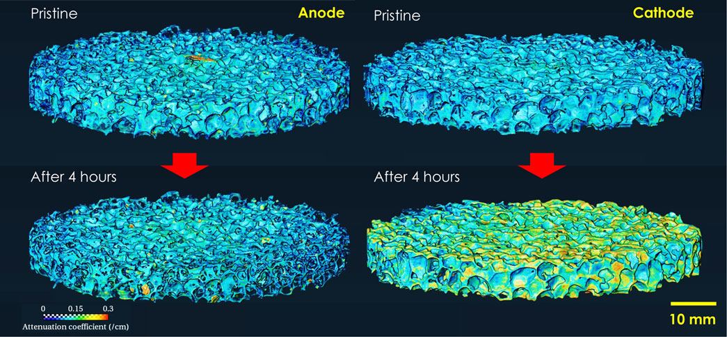
FIGURE 2. Reconstructed 3D volume of porous Al foam electrodes before and after a 4-h electrocoagulation experiment.
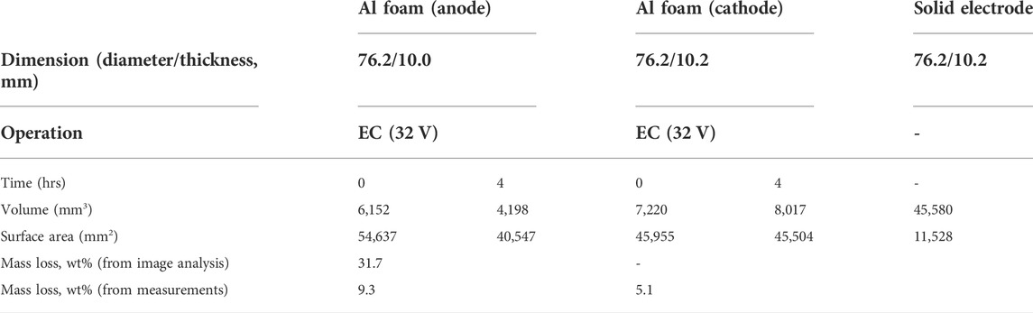
TABLE 1. Characteristics of porous Al foam electrodes corresponding to Figure 1.
Further image analysis results for the images of Figure 2 are shown in Figure 3 where the volume is measured vs. thickness of the electrodes. It is shown that the volume of the anode was significantly decreased after 4 h of electrocoagulation, which is explained by the mass loss of anode due to aluminum dissolution. However, the volume of the cathode significantly increased even though a 5 wt% mass loss was observed after 4 h of electrocoagulation. Two physicochemical reactions including salt deposition and dissolution occur at the surface. The water splitting reaction generates OH− ions, resulting in the formation of Al(OH)4-. Aluminum hydroxide layers are delaminated with gas evolution during the EC reaction, resulting in overall mass loss and volume change (Liu et al., 2022). Simultaneously, a significant mass of salts such as Si, Mg, and Ca deposit on the cathode, resulting in surface chemistry changes with increase in surface area. The presence of aluminum hydroxide, however, which contains neutron absorbing hydrogen, may be the reason of volume increase because it increases the visibility of electrode mass. It is also shown that the thickness of the anode decreased, while the thickness of the cathode remained almost the same after 4 h electrocoagulation.
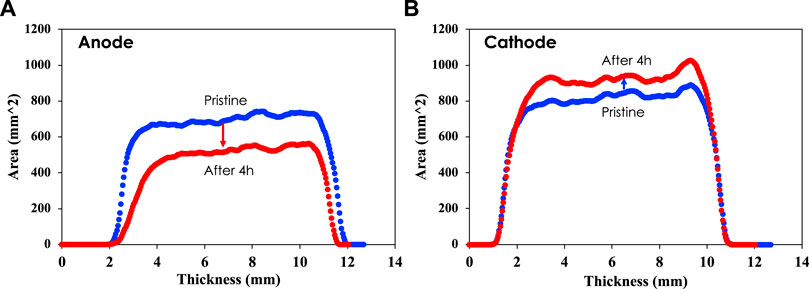
FIGURE 3. 3D image analysis providing the area of each electrode vs. thickness of the anode (A) and cathode (B).
Figure 4 reveals that the neutron attenuation coefficient of the cathode was significantly increased after 4-h electrocoagulation compared to that of the anode. This is because of aluminum hydroxide deposited on the surface, which includes hydrogen that strongly attenuates the neutron beam. The two peaks observed for the cathode attenuation coefficient reveal that most of the material deposition occurred near the external surface of the cathode. Significant deposition also occurred in the interior surface of the cathode, which led to an overall increase in the attenuation coefficient. The anode also showed a small increase in the attenuation coefficient due to an oxide layer forming on its surface during electro-dissolution. The results show that attenuation of the neutron beam depends strongly on the material penetrated by neutrons. Neutron attenuation by aluminum of a certain thickness can be less effective compared to neutron attenuation by an oxide film on its surface or a thin film that contains hydrogen. The formation of an oxide layer on the electrodes increases the resistance of the electrodes, which can lead to passivation and energy increase for a certain dosage. The oxide layer on the anode could be associated with silica deposition, which was found in SEM-EDS analysis of the anode [Supplementary Information]. In previous work on Al EC of simulated groundwater, we reported that oxygen on Al anode is associated with silicate deposition from the treated groundwater, while aluminum hydroxide deposits on the cathode (Liu et al., 2022). Due to the intensive Al dissolution at the anode, the silicate layer is not significant enough to increase the thickness of the anode.
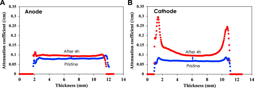
FIGURE 4. Neutron attenuation of anode (A) and cathode (B). 3D image analysis shows that the neutron attenuation coefficient increases more for the cathode than for the anode.
In general, the attenuation coefficient characterizes how easily a volume of material can be penetrated by a beam of light, sound, particle, or other energy or matter, in this case neutrons. Here, it is suggested that the image analysis results presented in Figures 2–4 are associated with chemistry changes on the surface of the anode and cathode, which are related to formation of aluminum oxide on the anode and deposition of hydroxides on the cathode. Specifically, hydrogen-containing compounds such as aluminum hydroxides, deposited on the surface of the cathode, are the reason for the significant increase in the attenuation coefficient after electrocoagulation. Aluminum hydroxide, the major component of the slurry, can be characterized by XRD and FTIR. (Liu et al., 2022).
Microscopic surface analysis with EDS further characterizes the surface chemistry of both anode and cathode. SEM images shown in Supplementary Figure S1 indicate that corrosion occurred over time at the anode, where micron-scale roughness significantly increased. The Al foam structure can be categorized into strut, cell, and window. It appears that anodic dissolution occurs over the entire electrode surface, including inner and outer area, compared to the as-received sample. However, intensive corrosion mainly occurs at the area of strut, which is the outer surface of foam, as shown in Supplementary Figure S1B, and the upper side wall of the cell (i.e., red arrows indicated in Supplementary Figure S1C). Significant corrosion cannot be seen at the bottom and the downward wall of the cell [Supplementary Figure S1B]. SEM-EDS results in Supplementary Figure S1D indicate that more oxygen was detected on the surface of the corroded area, which is associated with oxide formation on the anode surface during Al dissolution. SEM images shown in Supplementary Figure S2 indicate that the cathode surface significantly changed after electrocoagulation which is due to slurry precipitation, salt crystalline formation, and delamination of oxidized surface films by gas generation at the surface. Note that surface deposition occurs all over the porous electrode including top strut, cell wall, and bottom. SEM-EDS analysis in Supplementary Figure S2C shows that additional Mg, Ca, Si, and C elements were found on the cathode surface, compared to the anode surface. The Mg, Ca, Si, and C are components of groundwater. These dissolved elements participated in complexation with the generated Al species from the anode, and precipitated flocs were deposited on the cathode surface. Meanwhile, evolved gas and hydroxide ions from the cathode oxidized the surface and eventually delaminated the oxide films, resulting in overall mass loss. These surface phenomena can be correlated with the electrode surface area and attenuation coefficient measurements in neutron imaging analysis. The elements detected by SEM-EDS analysis have fairly small neutron cross-sections. The increase in anode may be due to F, but in cathode, H in deposited hydroxides is most likely the cause of the elevated attenuation coefficient.
Small pore sized aluminum foam
Similar EC experiments were carried out using small-pore-size Al foam electrodes of 1-inch diameter with 40 ppi to investigate structural effects, internal electrode dissolution and salt deposition. Sample preparation and post-treatment analyses are the same as for the large-pore-size Al foam. Figure 5A shows the EC setup with the small-pore-size Al electrodes and how the electrodes change after 12 h of EC and after rinsing and drying. The sides of cylindrical electrodes faced each other during the EC experiment. Figure 5B presents the electrical current histories for 32-V applied voltage during runs 1, 2, and 3. The observed current of ∼0.12 A was significantly smaller than that of large-pore-size electrodes (0.65–0.9 A) due to the smaller electrode area. Figure 5C shows that the anode was dissolved out, resulting in approximately 17.8 wt% loss after a total of 12-h electrocoagulation time, while the cathode lost approximately 4.3 wt% at the same time. Similar to the large-pore-size electrodes, the cathode color changed from gray to black, while the anode color remained unchanged after the experiment.
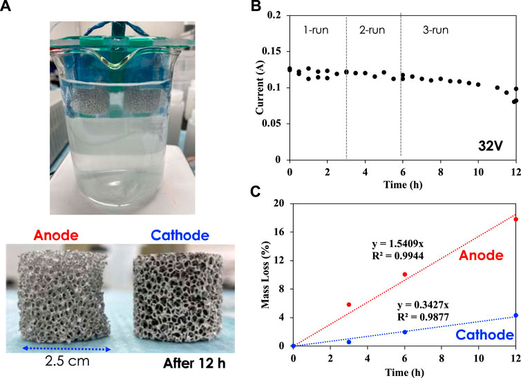
FIGURE 5. (A) Electrocoagulation experiments with porous Al foam electrodes (1-inch diameter and thickness) in simulated groundwater; (B) Electrical current vs. time at 32 V; (C) Mass loss of anode and cathode electrodes over time.
Figure 6 shows 3D structural views reconstructed from the nCT scans of both electrodes before and after 12 h of EC time. Table 2 shows the characteristic dimensions from the analysis of nCT images. The pristine small-pores Al electrodes have ∼10 times smaller solid Al volume, compared to a solid nonporous electrode with the same nominal dimensions, while their surface area is ∼4.3 times larger than that of solid electrodes [Table 2]. It appears that the side of the anode facing the cathode corroded out after the 12 h of EC experiment. The surface area of the anode significantly decreased from 13,300 mm2 to 10,647 mm2, corresponding to 20.8 wt% reduction. The mass loss estimated from image analysis is similar to the measured mass loss. However, the surface area of the cathode was not significantly changed, compared to that of the pristine electrode. The decrease in volume and surface area of the cathode after 6 h EC, as shown in Table 2, may be associated with a higher extent of oxide film delamination at the top surfaces, compared to the deposition rate, while the extent of slurry and salt accumulation in inner pores may have exceeded the rate of delamination between 6 and 12 h. Note that the mass loss of the cathode estimated from image analysis is similar to the actual mass loss. Similar color changes observed for the large-pores cathode were also observed for the small-pores cathode due to attenuation coefficient changes [Supplementary Information].
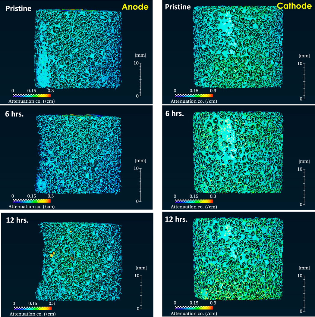
FIGURE 6. Reconstructed 3D volume of porous Al foam electrodes (small pores) before and after 6-hours and 12-hours electrocoagulation experiments.
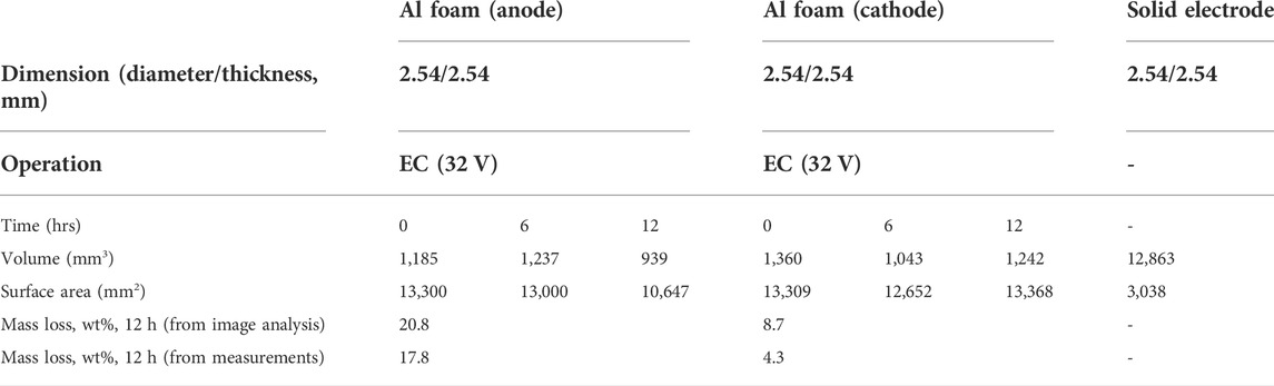
TABLE 2. Characteristics of porous Al foam electrodes corresponding to Figure 6.
Electrode dissolution occurred at the internal surface of the anode, but the penetration depth was limited to a few millimeters below at the first pore layer. Supplementary Figure S3A shows that corrosion of the Al foam occurred randomly at nodes and struts. Most of the corroded surface was found at the top pore layers. SEM-EDS results in Supplementary Figure S3B indicate that the corroded area exhibits Al, O, and Si, which are associated with oxide formation on the anode surface during Al dissolution. SEM images shown in Supplementary Figure S4A indicate that the cathode surface was significantly changed after EC. Cathodic surface deposition occurred all over the porous electrode including top strut and cell wall at the first pore layer. The second layer did not show significant deposition. This feature corresponds to the sharp increase of neutron attenuation at the top surface [Supplementary Information]. SEM-EDS analysis in Supplementary Figure S4B shows that additional Mg, Ca, Si, and C elements were found on the cathode surface, compared to the anode surface. The chemical composition is very similar to that found on the surface of the large-pores cathode.
Based on neutron and microscopic image analysis, anodic corrosion and cathodic deposition features are identified (Supplementary Table S1). For the anode, although corrosion occurred everywhere in the pores, most of the corrosion occurred at the top surface and upper wall. When the open pore size was significantly reduced, corrosion occurred on the sub-layer wall and even at the deep bottom of the cell in the first layer. This behavior suggests that a deeper-surface foam with dense and small pores can be used for effective electrode surface to reduce electric power requirements. For the cathode, sludge deposition occurred mostly on the first porous layer. While further deposition in sub-layers could not be seen, long-term operation is expected to lead to passivation of the top layer and participation of sub-layers in electrochemical reactions. This expected behavior would mean that porous electrodes will have the benefit of longer-term stable operation compared to nonporous electrodes.
Energy comparison
The amount of energy required for aluminum dissolution is over 4 times lower for the porous electrode compared to that of the solid electrode (Figure 7). This is largely due to the high surface area of the porous electrode which allows easier electron transfer for the aluminum metal to form aluminum ions at the anode. The high surface area of the porous electrode also leads to more contact between the electrode and the electrolyte, thus helping in reducing the amount of energy. Since the amount of total aluminum dissolved is same in both cases, the energy per unit mass of aluminum dissolved is over 4 times lower for the porous electrode compared to that of the solid electrode. The lower energy required for porous electrodes is encouraging for industrial application of electrocoagulation since the energy demand is one of the main disadvantages of the technology. Also, with the rising cost of energy and the need for changes in the current process to reduce the energy needed, using porous electrode could be one of the pathways towards achieving that goal.
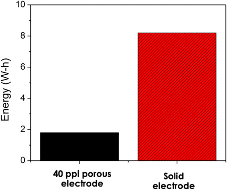
FIGURE 7. Energy comparison between solid electrode and the 40ppi porous electrode.
Conclusion
Electrocoagulation of simulated groundwater using porous Al electrodes was evaluated through neutron tomography and microscopic analysis to provide a better understanding of the micro/macro-scale changes on the surface of the electrodes. For the anode, most of the Al dissolution occurred on the outer electrode surface; however, nCT indicated that the inner surface of the open-pore walls also participated in Al dissolution, making the electrocoagulation process more effective and energy efficient compared to solid electrodes. Smaller pore-size foam with 40 ppi showed deeper penetrated dissolution compared to the large pore-size foam with five ppi. For the cathode, the entire inner surface within a certain depth was involved in cathodic deposition reactions although nCT and SEM indicated that most deposition occurred near the outer surface. Porous electrodes provide a larger surface area compared to that of solid nonporous electrodes, thus reducing energy consumption by 4 times. Further investigation on the influence of pore size and porosity, as well as electrode material, e.g., iron instead of aluminum electrodes, is needed to maximize the benefits of porous electrodes in electrocoagulation.
Data availability statement
The raw data supporting the conclusions of this article will be made available by the authors, without undue reservation.
Author contributions
GJ performed experiments and characterization work and wrote the manuscript. YZ supervised the neutron tomography experiments and performed analysis of the data. JK supervised the characterization work. YB analyzed the performance of the electrodes and wrote parts of the manuscript. MH provided useful comments in the analysis of the data and supervised the work at Georgia Tech. DJ provided useful comments in the analysis of the data and reviewed the manuscript. CT conceived the use of porous electrodes and the use of the neutron tomography technique to investigate the performance of the electrodes. He wrote parts of the manuscript and reviewed multiple versions of the manuscript.
Funding
This work was supported by the National Alliance for Water Innovation (NAWI), through funding from the U.S. Department of Energy, Office of Energy Efficiency and Renewable Energy, Advanced Manufacturing Office, under Funding Opportunity Announcement DE-FOA-0001905.
Acknowledgments
The authors are grateful to Erik Stringfellow for instrument support, and Qiu Zhang for chemistry laboratory support at the ORNL neutron facility. The research was conducted at Oak Ridge National Laboratory (ORNL), which is managed by UT Battelle, LLC, for the US Department of Energy (DOE) under contract DE-AC05-00OR22725. Neutron tomography and materials characterization (SEM) used resources at the High Flux Isotope Reactor and the Center for Nanophase Materials Sciences, all of which are DOE office of Science User Facility operated by Oak Ridge National Laboratory.
Conflict of interest
The authors declare that the research was conducted in the absence of any commercial or financial relationships that could be construed as a potential conflict of interest.
Publisher’s note
All claims expressed in this article are solely those of the authors and do not necessarily represent those of their affiliated organizations, or those of the publisher, the editors and the reviewers. Any product that may be evaluated in this article, or claim that may be made by its manufacturer, is not guaranteed or endorsed by the publisher.
Supplementary material
The Supplementary Material for this article can be found online at: https://www.frontiersin.org/articles/10.3389/fceng.2022.1046627/full#supplementary-material
References
Agency, I. A. E. (2008). Neutron imaging: A non-destructive tool for materials testing. IAEA-TECDOC Series.
Alam, R., Sheob, M., Saeed, B., Khan, S. U., Shirinkar, M., Frontistis, Z., et al. (2021). Use of electrocoagulation for treatment of pharmaceutical compounds in water/wastewater: A review exploring opportunities and challenges. Water 13, 2105. doi:10.3390/w13152105
Bao, W., Tang, X., Guo, X., Choi, S., Wang, C., Gogotsi, Y., et al. (2018). Porous cryo-dried MXene for efficient capacitive deionization. Joule 2, 778–787. doi:10.1016/j.joule.2018.02.018
Crow, L., Robertson, L., Bilheux, H., Fleenor, M., Iverson, E., Tong, X., et al. (2011). The CG1 instrument development test station at the high flux isotope reactor. Nucl. Instrum. Methods Phys. Res. Sect. A Accel. Spectrom. Detect. Assoc. Equip. 634, S71–S74. doi:10.1016/j.nima.2010.06.213
de Levie, R. (1963). On porous electrodes in electrolyte solutions. Electrochimica Acta 8, 751–780. doi:10.1016/0013-4686(63)80042-0
Deghles, A., and Kurt, U. (2016). Treatment of tannery wastewater by a hybrid electrocoagulation/electrodialysis process. Chem. Eng. Process. Process Intensif. 104, 43–50. doi:10.1016/j.cep.2016.02.009
Dunn, D., and Newman, J. (2000). Predictions of specific energies and specific powers of double-layer capacitors using a simplified model. J. Electrochem. Soc. 147, 820–830. doi:10.1149/1.1393278
Ge, J., Qu, J., Lei, P., and Liu, H. (2004). New bipolar electrocoagulation-electroflotation process for the treatment of laundry wastewater. Sep. Purif. Technol. 36, 33–39. doi:10.1016/S1383-5866(03)00150-3
Hemmatifar, A., Stadermann, M., and Santiago, J. G. (2015). Two-dimensional porous electrode model for capacitive deionization. J. Phys. Chem. C 119, 24681–24694. doi:10.1021/acs.jpcc.5b05847
Johnson, A. M., and Newman, J. (1971). Desalting by means of porous carbon electrodes. J. Electrochem. Soc. 118, 510–517. doi:10.1149/1.2408094
Kaestner, A. P. (2022). MuhRec-A new tomography reconstructor. Nucl. Instrum. Methods Phys. Res. Sect. A Accel. Spectrom. Detect. Assoc. Equip. 651, 156–160. doi:10.1016/j.nima.2011.01.129
Kardjilov, N., and Festa, G. (2017). in Neutron methods for archaeology and cultural heritage. Editors N. Kardjilov, and G. Festa (Cham: Springer International Publishing).
Kardjilov, N., Manke, I., Woracek, R., Hilger, A., and Banhart, J. (2018). Advances in neutron imaging. Mat. TodayKidlingt. 21, 652–672. doi:10.1016/j.mattod.2018.03.001
Liu, Y.-H., Bootwala, Y. Z., Jang, G. G., Keum, J. K., Khor, C. M., Hoek, E. M. V., et al. (2022). Electroprecipitation mechanism enabling silica and hardness removal through aluminum-based electrocoagulation. ACS Es. Trans. Eng. 2, 1200–1210. doi:10.1021/acsestengg.1c00433
Liu, Z., Yuan, X., Zhang, S., Wang, J., Huang, Q., Yu, N., et al. (2019). Three-dimensional ordered porous electrode materials for electrochemical energy storage. NPG Asia Mat. 11, 12–21. doi:10.1038/s41427-019-0112-3
López-Guzmán, M., Flores-Hidalgo, M. A., and Reynoso-Cuevas, L. (2021). Electrocoagulation process: An approach to continuous processes, reactors design, pharmaceuticals removal, and hybrid systems—A review. Processes 9, 1831. doi:10.3390/pr9101831
Magnisali, E., Yan, Q., and Vayenas, D. (2022). Electrocoagulation as a revived wastewater treatment method-practical approaches: A review. J. Chem. Technol. Biotechnol. 97, 9–25. doi:10.1002/jctb.6880
Mohora, E., Rončević, S., Agbaba, J., Tubić, A., Mitić, M., Klašnja, M., et al. (2014). Removal of arsenic from groundwater rich in natural organic matter (NOM) by continuous electrocoagulation/flocculation (ECF). Sep. Purif. Technol. 136, 150–156. doi:10.1016/j.seppur.2014.09.006
Newman, J., and Tiedemann, W. (1975). Porous‐electrode theory with battery applications. AIChE J. 21, 25–41. doi:10.1002/aic.690210103
Newman, J., and Tobias, C. W. (1962). Theoretical analysis of current distribution in porous electrodes. J. Electrochem. Soc. 109, 1183–1191. doi:10.1149/1.2425269
Santhanagopalan, S., and White, R. E. (2009). ELECTRODES | porous electrodes. Encycl. Electrochem. Power Sources, 110–120. doi:10.1016/B978-044452745-5.00027-7
Santodonato, L., Bilheux., H., Bailey., B., Bilheux., J., Nguyen., P., Tremsin, A., et al. (2015). The CG-1D neutron imaging beamline at the Oak Ridge national laboratory high flux isotope reactor. Phys. Procedia 69, 104–108. doi:10.1016/j.phpro.2015.07.015
Sharma, K., Kim, Y.-H., Gabitto, J., Mayes, R. T., Yiacoumi, S., Bilheux, H. Z., et al. (2015). Transport of ions in mesoporous carbon electrodes during capacitive deionization of high-salinity solutions. Langmuir 31, 1038–1047. doi:10.1021/la5043102
Smith, K. C., and Dmello, R. (2016). Na-ion desalination (NID) enabled by Na-blocking membranes and symmetric Na-intercalation: Porous-electrode modeling. J. Electrochem. Soc. 163, A530–A539. doi:10.1149/2.0761603jes
Soffer, A., and Folman, M. (1972). The electrical double layer of high surface porous carbon electrode. J. Electroanal. Chem. Interfacial Electrochem. 38, 25–43. doi:10.1016/S0022-0728(72)80087-1
Stalling, D., Westerhoff, M., and Hege, H.-C. (2005). Amira: A highly interactive system for visual data analysis. Vis. Handb., 749–767. doi:10.1016/B978-012387582-2/50040-X
Sun, J., Lu, H., Lin, H., Huang, W., Li, H., Lu, J., et al. (2012). Boron doped diamond electrodes based on porous Ti substrates. Mater. Lett. 83, 112–114. doi:10.1016/j.matlet.2012.05.044
Tang, K., Yiacoumi, S., Li, Y., and Tsouris, C. (2019). Enhanced water desalination by increasing the electroconductivity of carbon powders for high performance flow-electrode capacitive deionization. ACS Sustain. Chem. Eng. 7, 1085–1094. doi:10.1021/acssuschemeng.8b04746
Tengattini, A., Lenoir, N., Andò, E., and Viggiani, G. (2021). Neutron imaging for geomechanics: A review. Geomechanics Energy Environ. 27, 100206. doi:10.1016/j.gete.2020.100206
Keywords: neutron tomography, electrocoagulation, porous aluminum electrodes, groundwater treatment, neutron imaging
Citation: Jang GG, Zhang Y, Keum JK, Bootwala YZ, Hatzell MC, Jassby D and Tsouris C (2022) Neutron tomography of porous aluminum electrodes used in electrocoagulation of groundwater. Front. Chem. Eng. 4:1046627. doi: 10.3389/fceng.2022.1046627
Received: 16 September 2022; Accepted: 19 October 2022;
Published: 03 November 2022.
Edited by:
J. Paul Chen, National University of Singapore, SingaporeReviewed by:
Chia-Hung Hou, National Taiwan University, TaiwanKaimin Shih, The University of Hong Kong, Hong Kong SAR, China
Copyright © 2022 Jang, Zhang, Keum, Bootwala, Hatzell, Jassby and Tsouris. This is an open-access article distributed under the terms of the Creative Commons Attribution License (CC BY). The use, distribution or reproduction in other forums is permitted, provided the original author(s) and the copyright owner(s) are credited and that the original publication in this journal is cited, in accordance with accepted academic practice. No use, distribution or reproduction is permitted which does not comply with these terms.
*Correspondence: C. Tsouris, dHNvdXJpc2NAb3JubC5nb3Y=