- 1Department of Electrical Engineering, Indian Institute of Technology Delhi, New Delhi, India
- 2Department of Electrical Engineering, Qatar University, Doha, Qatar
- 3Department of Electrical Engineering, College of Engineering, King Khalid University, Abha, Saudi Arabia
In rotor dynamics, the deviation of the shaft is a common phenomenon. The main reasons for the deviation are non-linear attractive forces, harmonic disturbances, system parameter variations, etc. Active magnetic bearings (AMBs) are used to support the rotor inside the air gap in rotating machines, thus avoiding wear and tear and possible breakdowns. This paper proposes a fuzzy sliding mode-inspired control (FSMIC) technique for the five-degrees-of-freedom (DOF) AMB system in the presence of system uncertainties and measurement noises. The fuzzy logic is used to estimate the auxiliary control input of the sliding mode control (SMC) to attenuate the chattering. The variable gains are designed with the help of superintended fuzzy logic to bring more flexibility to the controller performance. The stability analysis is presented with the help of the Lyapunov function candidate. The simulation studies for the AMB system under distinct types of control techniques, i.e., PID, SMC, and FSMIC, illustrate the effectiveness of the proposed control strategy.
1 Introduction
A magnetic bearing is a specific type of bearing which holds the rotor without physical contact with the stator, using electromagnets. Magnetic bearings that are controlled by a feedback control system are referred to as active magnetic bearings (AMBs). Conventional mechanical bearings were used in the industries to support the shaft with the help of physical contact or fluid films. In many critical applications (Bleuler et al., 2009), particularly those involving high-speed rotation, AMB systems have proved a better alternative in recent years. The advantages of AMB are efficient energy consumption, low friction losses, noise-free operation, longer lifetime, etc. (Saha and Nabi, 2016; Peng and Zhou, 2019; Saha et al., 2019).
Some examples of the use of the AMB system in different industrial applications are mentioned in the following text. In a study by Scharfe et al. (2001), a magnetically suspended momentum wheel was designed for aerospace applications, specifically to support small and medium satellites. A flywheel-based energy storage system built on superconducting AMB was presented by Koshizuka et al. (2003). In a study by Knospe (2007), a high-speed machine spindle for the application of metal cutting was discussed. An axial AMB-based blood pump was designed by Ricci et al. (2016) for medical industry application. AMB is also used extensively for turbomachines (Aenis et al., 2002) and to support rotor dynamics (Tang et al., 2014).
Most AMB systems encounter problems such as vibration phenomena, mass imbalance, and harmonic disturbances (Esfahani et al., 2013; Liu et al., 2019). Moreover, in general, the AMB system is unstable and uncertain. Hence, the use of control techniques for the balance and control of the AMB system is crucial. A significant amount of research has been reported in the recent decades by Mushi et al. (2011) and Noshadi et al. (2014) to stabilize and regulate the AMB system.
The literature has few reports of control technique applications to the AMB system. The decentralized nature of classical control strategies such as PI/PD allows for controlling the shaft’s location of the AMB system (Polajžer et al., 2006). The gains of classical control techniques such as the proportional integral derivative controller (PID) are normally fixed. Thus, nowadays, PID control is combined with other control techniques to update the gains. In studies by Chen et al. (2009) and Chang and Chen (2009), a way to update the fixed gains by using fuzzy logic and an adaptive genetic algorithm has been presented. However, the performance of PID control is affected when the system dynamics contain uncertainties. Therefore, in a study by Kang et al. (2011), an LMI-based H∞ control was proposed for the regulation of the AMB system. Also, H∞ control of the AMB system was presented by Cole et al. (2017) after considering the vibration of rotor dynamics. The model predictive control for the AMB was discussed by Huang et al. (2007) and Bonfitto et al. (2018). De Miras et al. (2013) investigated the use of model-free control in the aspects of the AMB system. The adaptive control strategy has also been used to control the AMB system with a moving base (Sivrioglu, 2007).
The deviations of the rotor from the nominal position and unbalancing due to mass imbalance are the main challenges in the case of control of the AMB system. To tackle these phenomena, sliding mode control (SMC) has been used in different research works because of the advantages of robustness, faster convergence, ease of design, and better transient and steady-state responses (Edwards and Spurgeon, 1998; Amrr et al., 2022a). In a study by Kang et al. (2010), a conventional SMC is implemented for the AMB system with a movable base that only ensures the asymptotic convergence of system states. An integral SMC control for the regulation problem of the five-degrees-of-freedom (DOF) AMB system is presented in a study by Lin et al. (2011), where the gains are updated using a neural network. In the aforementioned SMC techniques, the issue of the chattering phenomenon (Shtessel et al., 2014) is mainly addressed using the boundary layer technique. This technique resolves the problem of chattering at the cost of the robustness of SMC (Amrr et al., 2022c). Another effective approach to address the chattering is a higher-order SMC scheme (Levant, 2003; Davila et al., 2005; Defoort et al., 2009; Utkin et al., 2020). The higher-order SMC strategies have also been used for the uncertain AMB system, and the recent results were reported by Saha et al. (2020), Amrr and Alturki (2021), and Saha et al. (2021). In a study by Saha et al. (2020), an adaptive-based second-order SMC was designed, whereas Saha et al. (2021) extended this result to a third-order SMC approach. Likewise, non-singular fast terminal sliding surface-based second-order SMC was proposed by Amrr and Alturki (2021) and Amrr et al. (2022b) to resolve the issue of chattering. Although these schemes are effective in solving the problem of unwanted chattering, they have high computational complexities, the control design is mathematically intensive, and it also requires an additional differential observer to estimate the higher-order derivatives of system states (Saha et al., 2020; Saha et al., 2021).
The chattering in SMC arises due to the switching characteristics, so a good alternative to this is the use of the approximation method. Therefore, a worthwhile approximation method to attenuate the chattering is the auxiliary control by the fuzzy logic algorithm (Lo and Kuo, 1998; Tong and Li, 2003). Since Lotfi A. Zadeh originally proposed fuzzy logic (FL) and fuzzy set theory in the 1970s, they have drawn much interest from scholars as an emerging field. FL has been employed in a variety of applications, including control, communication, the creation of integrated circuits, and medical fields. However, fuzzy logic control (FLC) has been the most effective application of FL. Numerous scholars have looked at the possibility of fuzzy control applications for active magnetic bearing control (Alassar et al., 2010; Amer et al., 2011; Su and Li, 2016). Fuzzy logic control has also been explored for the modeling of the AMB system from its input–output relation and combined with SMC for robust control of the system under gyroscopic effects, as can be seen in the study by Xu and Nonami (2003). The primary characteristic of FLC is the use of IF-THEN rules that are based on conventional control theories and human experiences. Such FL principles can be used to tackle chattering issues in traditional SMC theory. The fuzzy-based SMC (FSMC) combines FL and SMC theories and provides the benefits of both SMC and FLC (Palm, 1994; Li et al., 1997). The FSMC scheme is highly efficient in lowering the number of switches in the SMC approach without compromising the other system performances. By using the linguistic fuzzy rules, the system state trajectory may be brought back to the defined sliding surface by choosing either a big or tiny control force as it moves away from the sliding surface.
Fuzzy sliding mode control of a single DOF AMB system was presented in a study by Qin et al. (2011), where the tracking problem was effectively tackled. The reference tracking of the rotor was first performed using only nominal control input, and then to solve the problem of chattering, fuzzy logic was used along with the sliding mode control. However, the use of fuzzy sliding mode control for the stabilization of the MIMO AMB system has not been explored previously. Thus, this paper proposes a fuzzy SMC-inspired control with variable gain for the stabilization of the five-DOF AMB system, which, to the authors’ knowledge, has not been previously explored much.
The contributions of this paper can be summarized as follows:
• A fuzzy-based sliding mode-inspired control is designed for the regulation problem of the five-DOF AMB system subjected to the system uncertainties and measurement noise.
• The auxiliary control input is calculated using a Mamdani-based fuzzy inference with two inputs and one output to attenuate the chattering phenomenon, the auxiliary control input is estimated by two inputs one output Mamdani-based fuzzy inference engine. Also, a superintended fuzzy block is used to update the auxiliary control gains to bring flexibility to the controller design.
• Three different types of control techniques (PID, SMC, and FSMIC) have been compared for the AMB system to provide efficacy and validate the proposed control technique.
The paper is categorized as follows: the system descriptions for five-DOF AMB systems are introduced in the first section, and in the second section, the problem formulation is presented. In the next section, a fuzzy-based SMC-inspired control with a variable gain is proposed, and Lyapunov-based stability analysis is presented. The simulation results are discussed in the next section. Finally, the conclusion is drawn in the last section.
2 Five-DOF AMB system
Figure 1 shows a simplified version of the model given by Lin et al. (2011). The essential components are two identical radial AMBs (RAMBs) and a thrust AMB (TAMB) in addition to the motor and the shaft. The two RAMBs are used in the two endpoints of the shaft to control four DOF, and the TAMB is used to control the axial DOF.
The measurement of the shaft anomaly in the X−Y direction from the nominal air gap is detected by sensors placed in the two RAMBs. The shaft deviation in the Z direction is sensed by a single sensor installed in the TAMB. The sensors send the measurement signals to the controller, and, based on these deviations, the controller generates a control signal to make the deviations zero.
The system dynamics can be represented as follows after decoupling the coupling of the five axes (Sivrioglu, 2007; Lin et al., 2011):
where
where kfp, kfi, ktp, and kti are the stiffness related to position and current of the RAMB and the TAMB, respectively, while
To derive a control law for the fuzzy SMC, first, the system dynamics have to be formulated as first-order dynamics. The problem formulation for converting the first-order dynamics is discussed in the following section.
3 Problem formulation
Initially, the non-linear five-degrees-of-freedom AMB is converted into a linear model, and the coupling of states is removed by decoupling the dynamics. The parameters in system dynamics often fluctuate. Therefore, system dynamics will always suffer from some amount of uncertainty. In the case of practical applications, approximating the precise nominal values of system matrices A and B is challenging. Moreover, the decoupled term q can be considered as an uncertainty. Therefore, the nominal system parameters along with the uncertainties are presented as
where Anom and Bnom are the nominal values of A and B, respectively, the variations of time-varying system parameters are symbolized as
Assumption 1. The system states and its derivatives are measurable during the designing feedback.
Assumption 2. The variable n is slowly time-varying and bounded, i.e.,
Remark 1. The first-order derivative of states x can be derived by using a finite-time differentiator (Levant, 2007). This observer estimates the derivative of the input signal, and it is expressed as
where c1 > 0, c2 > 0, and c1 > c2. The variables
Substituting these new variables in Eq. 6 yields
Therefore, the main objective of the controller design is to stabilize the shaft in the nominal air gap by navigating the state variables (x1, x2, y1, y2, z) and its derivatives to zero despite system uncertainties and measurement noise, i.e.,
where the error is
4 The proposed control strategy
In this section, first, the fuzzy logic-based control law is designed, and the subsequent Lyapunov-based stability analysis is presented.
Sliding mode control is a non-linear technique that helps the system dynamics perform in a prescribed manner despite uncertainties. In this technique, the system dynamics are forced to reach a sliding surface and then slide on it. The most crucial part of designing the SMC is to choose the sliding surface carefully. Due to the flexibility of choosing proportional integral derivative (PID) gains in SMC control (Stepanenko et al., 1998), in this paper, a PID sliding surface is selected over a linear sliding surface to design an SMC-inspired controller. A PID sliding surface based on the error in the states can be presented as (Eker, 2006)
where
After getting s from Eq. 13, the change in sliding surface variable
In the absence of uncertainties (n) and taking
where KdBnom is invertible as both Kd and Bnom are diagonal. In the presence of uncertainties, an additional control input called auxiliary control is needed to suppress the uncertainties. Also, the auxiliary control is the main reason for the chattering problem in SMC control. To contain the chattering problem, the auxiliary control in this paper is estimated by fuzzy logic.
Fuzzy logic control (FLC) has been applied to many practical applications. The significant advantage of employing fuzzy logic is that it can transform the amount of vagueness into a human-understandable form (Bai and Roth, 2019). Therefore, in the absence of a mathematical model or mathematical model containing uncertainties, the issue can be efficiently dealt with by using fuzzy logic control. However, large numbers of rule base for higher-order systems complicate the analysis. Thus, much focus has been given to fuzzy SMC control (Yau and Chen, 2006; Roopaei and Jahromi, 2009; Lin et al., 2019).
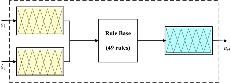
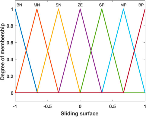
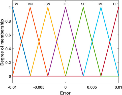
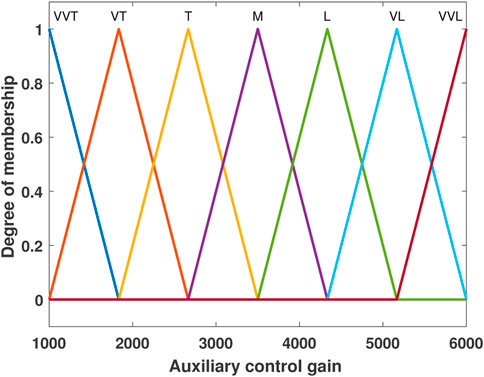
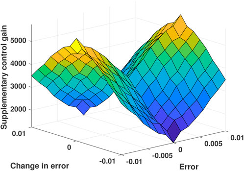
To suppress the chattering phenomenon, a fuzzy inference engine along with a fuzzy rule base is used, and FSMIC is proposed, which is similar to the design in studies by Yau and Chen (2006) and Roopaei and Jahromi (2009). Along with the estimation of auxiliary control input, the gain used for auxiliary control is also estimated using a fuzzy inference engine for the improvement of the system performance. This type of gain modification is normally known as superintended fuzzy control. The robustness of the system behavior is the main advantage of this method. The block diagram of fuzzy SMC-inspired control is shown in Figure 2. Fuzzy SMC block and superintended fuzzy block each consist of five components, where only one component of each block is shown in Figures 3 and 4, respectively. The Mamdani-based fuzzy inference method is used for both blocks to construct the two-input-one-output setup. In the case of fuzzy SMC block, inputs are sliding surface variable (s1) and change in sliding surface
The auxiliary control law is designed as
where Gq is the auxiliary control gain which can be represented as Gq = diag{gq1, gq2, gq3, gq4, gq5}, and uq is the output of fuzzy SMC block. The rules for the fuzzy control are produced by mapping input variables (s,
where i = 1, 2, …, 5.
The fuzzy membership functions and fuzzy rule base are designed for the fuzzy SMC and superintended block. Here, the fuzzy design of only one component inside those blocks is shown. However, the design for other components is the same as that for this one. The input variables (s1,
For the construction of the superintended fuzzy block, two inputs, which are errors (e1 and
The final control input can be represented as
4.1 Stability analysis
Theorem 1. Under Assumptions 1 and 2, the system dynamics (10) can be stabilized to the nominal position using the designed fuzzy-based SMC scheme (18). The proposed control law will steer the states and their derivatives to zero under the influence of model uncertainties and disturbances.Proof: The stability analysis is presented in two steps. In the first step, the convergence of the sliding surface is proved. Then, the convergence of error and its derivatives is shown.To show the convergence of the sliding surface, a positive definite Lyapunov function is chosen
Taking the time derivative of Eq. 19,
After taking the derivative of Eq. 13 and substituting it,
Now, putting the value of u from Eq. 18, it becomes
The output of the main component of the auxiliary control is mapped in the range of [−1, 1]. So,
Using the fuzzy SMC rule base in the aforementioned equation, i.e.,
where
Now, rearranging the dynamics,
After taking the derivative of Eq. 26,
Now, writing Eq. 27 in the state space form,
where the system matrix is in controllable canonical form, and all the coefficients are negative definite, making Eq. 28 a stable system. This proves that the errors and their derivatives will converge to zero asymptotically. In other words, the position of the rotor will asymptotically stabilize to the nominal air gap position.
5 Numerical analysis
This section presents the performance of the proposed fuzzy sliding mode-inspired control (FSMIC) for an uncertain five-DOF AMB system (10) on the MATLAB simulation platform. In order to establish the effectiveness of the proposed FSMIC design (18), this section also illustrates the comparative simulation analysis with a traditional SMC (Eker, 2006) and proportional integral derivative (PID) control (Ang et al., 2005). The parameter values of AMB system 1) are taken from Lin et al. (2011) and Lin et al. (2010) and given in Table 3. Notably, the rotor is considered to be rigid with a maximum operating speed of 4,800 rpm. The nominal air gap position is taken as xb = yb = 0.4 mm and zb = 0.5 mm. The bias currents in the coils for RAMB and TAMB are
where

TABLE 3. Five-DOF AMB system parameters (Lin et al., 2011; Lin et al., 2010).
5.1 Comparative simulation results
The comparative performances of PID, SMC, and FSMIC are presented through state response, input efforts, and total input variation. The time response of system states, which are rotor positions measured at left and right RAMBs and TAMB, is shown in Figure 9. The state response under PID control, traditional SMC scheme, and FSMIC algorithm are illustrated in the left, middle, and right subplots of Figure 9. It can be seen from the state response under PID and SMC schemes that the rotor deviations settle to zero from the given initial displacement within 0.63 s and 0.51 s, respectively. On the other hand, the proposed FSMIC technique helps converge the states to zero within 0.38 s. Therefore, the convergence rate is faster in the FSMIC scheme than in the comparative approaches. Moreover, there are noticeable overshoot and undershoot in the state trajectories under PID and SMC schemes, whereas there is no overshoot or undershoot in the proposed control strategy. The steady-state response is also presented in the zoomed-in plot in Figure 9, which shows that all the states remain in the neighborhood of zero with the residual bound range of 4 × 10⁻⁶ m. The bound of state x1 at the settling time is also mentioned in Table 4, which indicates that the FSMIC algorithm is performing better.
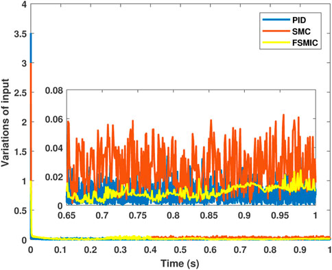
The control inputs’ response of these three schemes is shown in Figure 10. In the case of the PID control, the initial control current required is a little higher than the other two schemes, i.e., 1.2 A. Moreover, the transient response in the zoomed-in plot under the PID scheme shows the effect of measurement noise. On the other hand, the traditional SMC scheme experiences a chattering effect which is evident in the transient response. In contrast, the proposed FSMIC approach reduces the chattering to a great extent. The FSMIC scheme circumvents chattering due to the fuzzy-based approximation of the switching function in the sliding mode control design.
In addition, the reduction in input chattering can be quantified by calculating the total variation (TV) input throughout the simulation time. The expression of TV is defined as
where n is the total number of control input data samples. Figure 11 illustrates the performance of absolute fluctuations of control input over time. In Table 4, the calculated TV values for three control strategies are provided. Therefore, Table 4 and Figure 11 make it clear that the proposed approach has a lesser change in control input than the other two techniques. Consequently, the chattering is significantly minimized in FSMIC design.
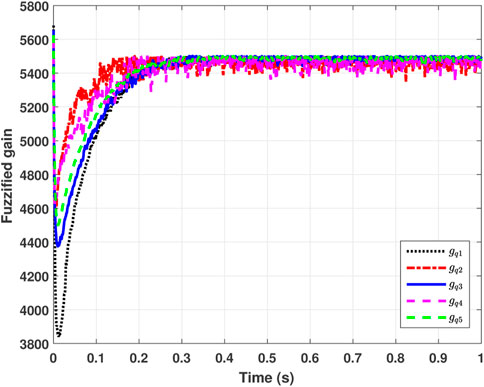
The time-varying control gains for the FSMIC scheme are also given in Figure 12. These gains vary between 1,000 and 6,000 and settle down to a constant value when the system reaches a steady state. The value of the gains Gq in the steady state is 5,500. It is important to note that the gains in the PID and SMC controllers are fixed. However, in the FSMIC design, auxiliary control gains are modified using the fuzzy logic algorithm. As a result, the variable gains under the FSMIC approach offer more flexibility over the other two comparative techniques.
Lastly, the amount of control effort executed in achieving the aforementioned results is also evaluated to determine the energy-efficient control performance. Therefore, the energy index value of these three control schemes is calculated using the following formula (Amrr et al., 2020):
The energy index values of the three control schemes are tabulated in Table 4, which shows that the proposed controller consumes the least energy. Hence, the proposed FSMIC algorithm is the most efficient.
6 Conclusion
This paper investigates the application of fuzzy-based SMC for the stabilization of the five-DOF AMB system under parametric uncertainties and disturbances. The fuzzy logic algorithm helps in reducing the chattering effect in the SMC design by approximating the variable gains of the auxiliary control. On the other hand, the SMC provides a faster state response with better invariance properties against disturbances. The comparative simulation analysis of the proposed scheme with traditional SMC and PID control is also presented in this study. The numerical results illustrate the efficacy of the proposed fuzzy SMC technique over the other two in terms of convergence time, maximum overshoot, energy consumption, and chattering suppression. However, one of the shortcomings of this scheme is that only asymptotic convergence of system trajectories is ensured theoretically. Therefore, future extension of this work could be focused on achieving the finite time results for state response as well. Furthermore, system complexity could also be enhanced by considering rotor flexibility and gyroscopic effect.
Data availability statement
The raw data supporting the conclusion of this article will be made available by the authors, without undue reservation.
Author contributions
SS contributed to the conception, methodology, and design of the study. SS carried out the formal analysis. SS organized the database and software coding. SS and SA performed the mathematical analysis and theoretical investigation. SS realized the simulation results. SS wrote the first draft of the manuscript. SA, JB, AA, and MN wrote sections of the manuscript. SS and SA revised the manuscript and addressed the reviewer’s comments. MN supervised this work. MN provided the laboratory resources. JB and AA arranged the funding. All authors contributed to manuscript revision and read and approved the submitted version.
Funding
The Deanship of Scientific Research at King Khalid University funded this work through Research Groups Program under grant no. RGP 2/91/43.
Acknowledgments
The authors extend their appreciation to the Deanship of Scientific Research at King Khalid University, Saudi Arabia, for funding this work through the Research Group Program under grant no. RGP 2/91/43.
Conflict of interest
The authors declare that the research was conducted in the absence of any commercial or financial relationships that could be construed as a potential conflict of interest.
Publisher’s note
All claims expressed in this article are solely those of the authors and do not necessarily represent those of their affiliated organizations, or those of the publisher, the editors, and the reviewers. Any product that may be evaluated in this article, or claim that may be made by its manufacturer, is not guaranteed or endorsed by the publisher.
References
Abooee, A., and Arefi, M. M. (2019). Robust finite-time stabilizers for five-degree-of-freedom active magnetic bearing system. J. Frankl. Inst. 356, 80–102. doi:10.1016/j.jfranklin.2018.08.026
Aenis, M., Knopf, E., and Nordmann, R. (2002). Active magnetic bearings for the identification and fault diagnosis in turbomachinery. Mechatronics 12, 1011–1021. doi:10.1016/s0957-4158(02)00009-0
Alassar, A. Z., Abuhadrous, I. M., and Elaydi, H. A. (2010). “Modeling and control of 5 dof robot arm using supervisory control,” in 2010 The 2nd International Conference on Computer and Automation Engineering (ICCAE) (IEEE), 351–355.
Amer, A. F., Sallam, E. A., and Elawady, W. M. (2011). Adaptive fuzzy sliding mode control using supervisory fuzzy control for 3 dof planar robot manipulators. Appl. Soft Comput. 11, 4943–4953. doi:10.1016/j.asoc.2011.06.005
Amrr, S. M., and Alturki, A. (2021). Robust control design for an active magnetic bearing system using advanced adaptive smc technique. IEEE Access 9, 155662–155672. doi:10.1109/access.2021.3129140
Amrr, S. M., Srivastava, J. P., and Nabi, M. (2020). Robust attitude stabilization of spacecraft under constrained network with hysteresis quantizer. IEEE J. Miniat. Air Space Syst. 2, 129–139. doi:10.1109/jmass.2020.3039977
Amrr, S. M., Ahmad, J., Waheed, S. A., Sarwar, A., Saidi, A. S., and Nabi, M. (2022a). Finite-time adaptive sliding mode control of a power converter under multiple uncertainties. Front. Energy Res. 10, 580. doi:10.3389/fenrg.2022.901606
Amrr, S. M., Alturki, A., and Zafar, K. (2022b). Advanced robust control design for the support of fast rotating shaft using active magnetic bearings. Transp. Eng. 10, 100139. doi:10.1016/j.treng.2022.100139
Amrr, S. M., Sarkar, R., Banerjee, A., Saidi, A. S., and Nabi, M. u. (2022c). Fault-tolerant finite-time adaptive higher order sliding mode control with optimized parameters for attitude stabilization of spacecraft. Int. J. Robust Nonlinear Control 32, 2845–2863. doi:10.1002/rnc.5934
Ang, K. H., Chong, G., and Li, Y. (2005). Pid control system analysis, design, and technology. IEEE Trans. Control Syst. Technol. 13, 559–576. doi:10.1109/tcst.2005.847331
Bai, Y., and Roth, Z. S. (2019). “Fuzzy logic control systems,” in Classical and modern controls with microcontrollers (Springer), 437–511.
Bhat, S. P., and Bernstein, D. S. (2000). Finite-time stability of continuous autonomous systems. SIAM J. Control Optim. 38, 751–766. doi:10.1137/s0363012997321358
Bleuler, H., Cole, M., Keogh, P., Larsonneur, R., Maslen, E., Okada, Y., et al. (2009). Magnetic bearings: Theory, design, and application to rotating machinery. Verlag Berlin Heidelberg: Springer Science & Business Media.
Bonfitto, A., Castellanos Molina, L., Tonoli, A., and Amati, N. (2018). Offset-free model predictive control for active magnetic bearing systems. Actuators (Multidisciplinary Digital Publishing Institute), 7, 46.
Chang, L.-Y., and Chen, H.-C. (2009). Tuning of fractional pid controllers using adaptive genetic algorithm for active magnetic bearing system. WSEAS Trans. Syst. 8, 158–167.
Chen, K.-Y., Tung, P.-C., Tsai, M.-T., and Fan, Y.-H. (2009). A self-tuning fuzzy pid-type controller design for unbalance compensation in an active magnetic bearing. Expert Syst. Appl. 36, 8560–8570. doi:10.1016/j.eswa.2008.10.055
Cole, M. O., Chamroon, C., and Keogh, P. S. (2017). H-infinity controller design for active magnetic bearings considering nonlinear vibrational rotordynamics. Mech. Eng. J. 4, 16–00716. doi:10.1299/mej.16-00716
Davila, J., Fridman, L., and Levant, A. (2005). Second-order sliding-mode observer for mechanical systems. IEEE Trans. Autom. Contr. 50, 1785–1789. doi:10.1109/tac.2005.858636
De Miras, J., Join, C., Fliess, M., Riachy, S., and Bonnet, S. (2013). “Active magnetic bearing: A new step for model-free control,” in 52nd IEEE Conference on Decision and Control (IEEE), 7449–7454.
Defoort, M., Floquet, T., Kokosy, A., and Perruquetti, W. (2009). A novel higher order sliding mode control scheme. Syst. Control Lett. 58, 102–108. doi:10.1016/j.sysconle.2008.09.004
Edwards, C., and Spurgeon, S. (1998). Sliding mode control: theory and applications. London: CRC Press.
Eker, I. (2006). Sliding mode control with pid sliding surface and experimental application to an electromechanical plant. ISA Trans. 45, 109–118. doi:10.1016/s0019-0578(07)60070-6
Esfahani, A. F., Jastrzebski, R. P., Kauranne, T., Haario, H., and Pyrhönen, O. (2013). “Novel methods of chaos detection of active magnetic bearing (amb) system by signal analysis,” in 2013 15th European Conference on Power Electronics and Applications (EPE) (IEEE), 1–9.
Huang, J., Wang, L., and Huang, Y. (2007). Continuous time model predictive control for a magnetic bearing system. PIERS online 3, 202–208. doi:10.2529/piers060906214406
Kang, M. S., Lyou, J., and Lee, J. K. (2010). Sliding mode control for an active magnetic bearing system subject to base motion. Mechatronics 20, 171–178. doi:10.1016/j.mechatronics.2009.09.010
Kang, H., Oh, S.-Y., and Song, O. (2011). H∞ control of a rotor-magnetic bearing system based on linear matrix inequalities. J. Vib. Control 17, 291–300. doi:10.1177/1077546310362449
Knospe, C. R. (2007). Active magnetic bearings for machining applications. IFAC Proc. Vol. 15, 307–312. doi:10.1016/s1474-6670(17)31072-8
Koshizuka, N., Ishikawa, F., Nasu, H., Murakami, M., Matsunaga, K., Saito, S., et al. (2003). Progress of superconducting bearing technologies for flywheel energy storage systems. Phys. C. Supercond. 386, 444–450. doi:10.1016/s0921-4534(02)02206-2
Levant, A. (2003). Higher-order sliding modes, differentiation and output-feedback control. Int. J. Control 76, 924–941. doi:10.1080/0020717031000099029
Levant, A. (2007). Principles of 2-sliding mode design. Automatica 43, 576–586. doi:10.1016/j.automatica.2006.10.008
Li, H.-X., Gatland, H., and Green, A. (1997). Fuzzy variable structure control. IEEE Trans. Syst. Man. Cybern. B 27, 306–312. doi:10.1109/3477.558824
Lin, F., Chen, S., and Huang, M. (2010). Tracking control of thrust active magnetic bearing system via hermite polynomial-based recurrent neural network. IET Electr. Power Appl. 4, 701–714. doi:10.1049/iet-epa.2010.0068
Lin, F.-J., Chen, S.-Y., and Huang, M.-S. (2011). Intelligent double integral sliding-mode control for five-degree-of-freedom active magnetic bearing system. IET control Theory & Appl. 5, 1287–1303. doi:10.1049/iet-cta.2010.0237
Lin, B., Su, X., and Li, X. (2019). Fuzzy sliding mode control for active suspension system with proportional differential sliding mode observer. Asian J. Control 21, 264–276. doi:10.1002/asjc.1882
Liu, Y., Ming, S., Zhao, S., Han, J., and Ma, Y. (2019). Research on automatic balance control of active magnetic bearing-rigid rotor system. Shock Vib. 2019, 1–13. doi:10.1155/2019/3094215
Lo, J.-C., and Kuo, Y.-H. (1998). Decoupled fuzzy sliding-mode control. IEEE Trans. Fuzzy Syst. 6, 426–435. doi:10.1109/91.705510
Mushi, S. E., Lin, Z., and Allaire, P. E. (2011). Design, construction, and modeling of a flexible rotor active magnetic bearing test rig. Ieee. ASME. Trans. Mechatron. 17, 1170–1182. doi:10.1109/tmech.2011.2160456
Noshadi, A., Shi, J., Poolton, S., Lee, W., and Kalam, A. (2014). “Comprehensive experimental study on the stabilization of active magnetic bearing system,” in 2014 Australasian Universities Power Engineering Conference (AUPEC) (IEEE), 1–7.
Palm, R. (1994). Robust control by fuzzy sliding mode. Automatica 30, 1429–1437. doi:10.1016/0005-1098(94)90008-6
Peng, C., and Zhou, Q. (2019). Direct vibration force suppression for magnetically suspended motor based on synchronous rotating frame transformation. IEEE Access 7, 37639–37649. doi:10.1109/access.2019.2904745
Polajžer, B., Ritonja, J., Štumberger, G., Dolinar, D., and Lecointe, J.-P. (2006). Decentralized pi/pd position control for active magnetic bearings. Electr. Eng. 89, 53–59. doi:10.1007/s00202-005-0315-1
Qin, H.-l., Li, Z.-x., and Yuan, S. (2011). Application research of fuzzy sliding model control for active magnetic bearings. Comput. Simul. 48.
Ricci, M. R., Antaki, J. F., Verkaik, J. E., Paden, D. B., Snyder, S. T., Paden, B. E., et al. (2016). Magnetically-levitated blood pump with optimization method enabling miniaturization. US Patent 9,314,557. [Dataset]
Roopaei, M., and Jahromi, M. Z. (2009). Chattering-free fuzzy sliding mode control in mimo uncertain systems. Nonlinear Analysis Theory, Methods & Appl. 71, 4430–4437. doi:10.1016/j.na.2009.02.132
Saha, S., and Nabi, M. (2016). “A review on active magnetic bearing and exploitation of parametric model order reduction,” in IEEE proc. 11th International Conference on Industrial and Information Systems (ICIIS), Roorkee, India, 420–425.
Saha, S., Amrr, S. M., Nabi, M., and Iqbal, A. (2019). Reduced order modeling and sliding mode control of active magnetic bearing. IEEE Access 7, 113324–113334. doi:10.1109/access.2019.2935541
Saha, S., Amrr, S. M., and Nabi, M. (2020). Adaptive second order sliding mode control for the regulation of active magnetic bearing. IFAC-PapersOnLine 53, 1–6. doi:10.1016/j.ifacol.2020.06.001
Saha, S., Amrr, S. M., Saidi, A. S., Banerjee, A., and Nabi, M. (2021). Finite-time adaptive higher-order smc for the nonlinear five dof active magnetic bearing system. Electronics 10, 1333. doi:10.3390/electronics10111333
Scharfe, M., Roschke, T., Bindl, E., and Blonski, D. (2001). “Design and development of a compact magnetic bearing momentum wheel for micro and small satellites,” in 15th Annual/USU Conference on Small Satellites.
Sharma, A., Amrr, S. M., Nabi, M., and Banerjee, S. (2021). “Extended state observer based integral sliding mode control of maglev systems with enhanced chattering alleviation,” in 2021 Seventh Indian Control Conference (ICC) (IEEE), 242–247.
Sharma, A., Alturki, A., and Amrr, S. M. (2022). Extended state observer based integral sliding mode control for maglev system with fixed time convergence. IEEE Access 10, 93074–93083. doi:10.1109/access.2022.3204059
Shtessel, Y., Edwards, C., Fridman, L., and Levant, A. (2014). Sliding mode control and observation. New York: Springer.
Sivrioglu, S. (2007). Adaptive backstepping for switching control active magnetic bearing system with vibrating base. IET Control Theory & Appl. 1, 1054–1059. doi:10.1049/iet-cta:20050473
Stepanenko, Y., Cao, Y., and Su, C.-Y. (1998). Variable structure control of robotic manipulator with pid sliding surfaces. Int. J. Robust Nonlinear Control 8, 79–90. doi:10.1002/(sici)1099-1239(199801)8:1<79:aid-rnc313>3.0.co;2-v
Su, K.-H., and Li, C.-Y. (2016). “Supervisory fuzzy model control for magnetic levitation system,” in 2016 IEEE 13th International Conference on Networking, Sensing, and Control (ICNSC) (IEEE), 1–6.
Tang, J., Xiang, B., and Zhang, Y. (2014). Dynamic characteristics of the rotor in a magnetically suspended control moment gyroscope with active magnetic bearing and passive magnetic bearing. ISA Trans. 53, 1357–1365. doi:10.1016/j.isatra.2014.03.009
Tong, S., and Li, H.-X. (2003). Fuzzy adaptive sliding-mode control for mimo nonlinear systems. IEEE Trans. Fuzzy Syst. 11, 354–360. doi:10.1109/tfuzz.2003.812694
Utkin, V., Poznyak, A., Orlov, Y., and Polyakov, A. (2020). Conventional and high order sliding mode control. J. Frankl. Inst. 357, 10244–10261. doi:10.1016/j.jfranklin.2020.06.018
Wang, L.-X., and Mendel, J. M. (1992). Generating fuzzy rules by learning from examples. IEEE Trans. Syst. Man. Cybern. 22, 1414–1427. doi:10.1109/21.199466
Xu, Y., and Nonami, K. (2003). A fuzzy modeling of active magnetic bearing system and sliding mode control with robust hyperplane using μ-synthesis theory. JSME Int. J. Ser. C 46, 409–415. doi:10.1299/jsmec.46.409
Yau, H.-T., and Chen, C.-L. (2006). Chattering-free fuzzy sliding-mode control strategy for uncertain chaotic systems. Chaos, Solit. Fractals 30, 709–718. doi:10.1016/j.chaos.2006.03.077
Nomenclature
a length between COG and left RAMB
A stiffness matrix
Anom and Bnom nominal values of A and B
B control gain matrix
b length between COG and right RAMB
c distance between COG and end of the rotor
d diameter of the rotor
e error
Gq auxiliary control gain
ix1 control current for state x1
J transverse moment of inertia about the X and Y axis
Jz polar moment of inertia about the Z axis
Kd derivative gain
kfi current stiffness of RAMB
kfp position stiffness of RAMB
Ki integral gain
Kp proportional gain
kti current stiffness of TAMB
ktp position stiffness of TAMB
l distance between left RAMB and right RAMB
L length of the rotor
M mass matrix
m mass of the rotor
n lumped uncertainty
q term due to decoupling
s sliding surface
u control inputs
uq output of fuzzy SMC block
x states
Keywords: fuzzy logic, sliding mode control, active magnetic bearing, gain estimation, MIMO, stabilization
Citation: Saha S, Amrr SM, Bhutto JK, AlJohani AA and Nabi M (2022) Fuzzy logic control of five-DOF active magnetic bearing system based on sliding mode concept. Front. Control. Eng. 3:1008134. doi: 10.3389/fcteg.2022.1008134
Received: 31 July 2022; Accepted: 04 November 2022;
Published: 24 November 2022.
Edited by:
Dipankar Deb, Institute of Infrastructure, Technology, Research and Management, IndiaReviewed by:
Fadi Dohnal, Vorarlberg University of Applied Sciences, AustriaZheng Li, Hebei University of Science and Technology, China
Copyright © 2022 Saha, Amrr, Bhutto, AlJohani and Nabi. This is an open-access article distributed under the terms of the Creative Commons Attribution License (CC BY). The use, distribution or reproduction in other forums is permitted, provided the original author(s) and the copyright owner(s) are credited and that the original publication in this journal is cited, in accordance with accepted academic practice. No use, distribution or reproduction is permitted which does not comply with these terms.
*Correspondence: Syed Muhammad Amrr, c3llZGFtcnJAZ21haWwuY29t
 Sudipta Saha
 Syed Muhammad Amrr
 Javed Khan Bhutto3

