 Venkata Sundeep Seesala1
 Pravin Vasudeo Vaidya2
 Ragavi Rajasekharan3
 Atul Kumar Ojha1Subhodeep Jana1Barnali Pal4
 Santanu Dhara1*
- 1Biomaterials and Tissue Engineering Laboratory, School of Medical Science and Technology, Indian Institute of Technology Kharagpur, West Bengal, India
- 2Advanced Technology Development Centre, Indian Institute of Technology Kharagpur, West Bengal, India
- 3Rajendra Mishra School of Engineering and Entrepreneurship, Indian Institute of Technology Kharagpur, West Bengal, India
- 4B.C. Roy Technology Hospital, Indian Institute of Technology Kharagpur, West Bengal, India
All-ceramic fixed restorations are gaining popularity because of increased esthetic consciousness in the younger population. Monolith ceramic crowns and bridges are preferred to withstand masticatory loads where the availability of occlusal height is limited. Machining green blanks of ceramic with organic binders have been studied to reduce loss of final strength, cost, and wastage associated with milling partial sintered and sintered blanks. Notches on the surface/edge associated with green milling will disappear after sintering in contrast to sintered state machining where diamond polishing is essential. In this study, we explored a novel ceramic dough process to form a green body of alumina or 3 Mol% yttria-stabilized zirconium oxide (YSZ), and computer numerical control (CNC) machining was performed on the dried dough. Micro Computer Tomography analysis of the bridges after sintering revealed a negligible void volume, 0.06–0.08% of the total volume, with randomly dispersed voids. Precision analysis of the sintered bridges with respect to the reference file resulted in a deviation range of +0.56 to −0.79 mm, with negligible deviation on the cementation surface. The green machined surface had a roughness profile of 1.2–1.7 μm after machining and 2.2–2.4 μm after sintering, as revealed by 3D profilometry.
Introduction
The shaping of green ceramics, an age-old practice, has witnessed a dramatic change in recent decades with the advent of computer-aided design/computer-aided machining (CAD-CAM technology. Traditionally, mechanized milling into net shapes has been well established for both sintered and pre-sintered blanks using a variety of tools ranging from silicon carbide to diamond-coated burs. Especially in dental ceramics, machining of zirconia or alumina blanks for all-ceramic restorations has been widely explored owing to their esthetics and strength. Net shaping by direct ceramic machining of pre-sintered blanks with high accuracy resulted in increased interest of the dental community on fixed ceramic restorations by CAM (1); however, concerns regarding long-term strength, wastage of material, and tooling cost have hindered their widespread usage, making metal-ceramic restorations still a preferred choice for clinicians. Soft machining of pre-sintered zirconia blanks would be an easy alternative but has resulted in inaccurate fitting because of sintering shrinkage (2). Besides, machining of sintered and pre-sintered blanks leads to micro-cracks on the surface, which are detrimental to strength and reliability (3). In the case of zirconia restorations, these surface defects have resulted in a loss of characteristic flexural strength by about 40% (4). Monolithic zirconia crowns are usually preferred in clinical conditions where occlusal space was limited, necessitating machining of thin structural features. Also, grinding of sintered zirconia during chairside adjustment would result in monoclinic phase formation on the surface because of localized heating, enhancing surface defect propagation (5). These defects can be removed, to some extent, on the occlusal surface by polishing; however, on the cementation surface, defects produced by machining are difficult to polish because of the presence of narrow crevices and thin edges. In addition, any alteration on this surface negatively affects the fitting of the prepared tooth and the adhesiveness of the luting cement (6). Unfortunately, the concentration of tensile stresses during mastication mostly occurs on the cementation surface compared with an occlusal surface, predisposing the restoration to failure (4).
Green machining of components with fine complex features on non-sintered ceramics with and without polymer binders has been explored extensively in the past few years. Advantages such as cost-effectiveness and retention of characteristic strength in the final product owing to the minimized surface flaws were established. However, reproduction of fine edges or features during the machining of intricate models has been a hurdle, especially in dentures, where precise fitting on the prepared tooth and cuspal edges would be crucial. Recently, the focus has shifted to additive manufacturing techniques, such as stereolithography, selective laser sintering, and extrusion-based 3D printing, which allows for rapid manufacturing without material wastage; however, the density, strength, and resolution of the final components were not satisfactory for dental applications along with the high initial cost of the equipment (7, 8). The maximum densification achieved for selective laser-sintered zirconia dental restorations in combination with cold isostatic pressing before sintering was 86.6% (9). Femtosecond laser ablation was explored on the sintered blanks of alumina-toughened zirconia to machine a dental implant with superior surface finish having average roughness (Ra) of ~0.24 μm, but the defect formation at the subsurface layer was similar to conventional tooling (10). Hybrid techniques, such as picosecond laser machining on extrusion printed green body of alumina with hydroxyl propyl methyl cellulose binder, were studied to form 3D microchannels with cross-sectional size ~30 ×100 μm2 (11, 12). Machining a green zirconia body prepared by ceramic gel casting with polymer binders, such as epoxy resin, was suggested for net shaping dental crowns, but the minimum binder requirement was 10 wt%, and the article has demonstrated only a rough sketch of the molar crown (13). Probably, fine edges were difficult to replicate during green machining, as epoxy resins tend to be brittle with a hard surface after cross-linking. In this study, a novel ceramic dough technique by forming viscoplastic mixtures of alumina and zirconia was explored. These doughs were molded and dried to obtain soft green blanks followed by computer numerical control (CNC) machining with diamond-coated burs in the presence of a binder. Characteristics of green and sintered surfaces along with a part comparison of the extracted surface files after machining and sintering were studied for efficiency in the reproduction of thin features.
Materials and Methods
Green Body Preparation and Machining
A novel ceramic dough processing was used for forming ceramic green bodies with dense packing. Aluminum oxide powder (RG 4000, Almatis, Ludwigshafen, Germany) of particle size D50 = 0.6 μm, 3 mol.% yttria-stabilized zirconium oxide (3YSZ) (ANTS Ceramics, Maharashtra, India) of particle size in a range of 0.05–0.06 μm, stearic acid (Merck, Kenilworth, NJ, United States), poly-vinyl–acetate (CTS Europe, Portsmouth, United Kingdom), isopropanol (Merck, Kenilworth, NJ, United States) were the main ingredients. Additives, namely, triglycerides and stearic acid, were used to improve the workability and increase the dispersion of binder macromolecules and ceramic powders. The powders were mixed in required proportions with a binder (4 wt%) and a lubricant (2 wt%) and then mechanically mixed for about 5–10 min while adding propanol gradually to dissolve the binder. After achieving a cohesive consistency, the mixture was left undisturbed in a sealed container for 5–6 h to allow the absorption of the solvent by the binder. Kneading was performed for 3–5 min under ambient atmospheric conditions to prepare a homogenous defect-free dough, which was molded to blanks via plastic deformation. Detailed composition and procedure of forming a green blank along with the characterization of the wet dough were discussed elsewhere (14, 15).
After complete drying, the blanks were machined using a Roland tabletop CNC machine with diamond coated cutting tools DIA-BURS®, procured from MANI®, Japan. Depending on the machining step, round ball-shaped burs of BR40-49 (ISO 001/016-008) and pointed burs of TC11(ISO 160/016 FG) were used in this study. These tools were the commercially available burs used by dental surgeons for preparing cavities in carious teeth prior to restoration. The tools were fitted into a slot made on high-speed steel (HSS) blank of a used drill bit, which provided an option for tool change in the middle of the job. This was done to save time since the CNC performed in this study did not have an option for automatic tool change. Stereolithography (STL) files of the bridges were available on GRABCAD, an open-source online platform (16).
Machining was done in three steps: surfacing, followed by roughing, and finally finishing. Surfacing involves reducing the blank dimensions to fit the boundary dimensions of the final model. Hence, round-end tools were used with a higher feed rate to expedite the process. The roughing and finishing steps involve the machining of the actual model shape. Finishing was performed on a 0.2 mm margin, left out from the roughing model, with a much lower feed rate by reducing the depth of cut and path interval by up to 50%. The optimized machining parameters and tools involved are shown in Table 1. Path interval is the distance between each scan line during tool movement and depth of cut is the movement in the z-direction for each scan layer. X, Y, and Z speeds are the rates of tool displacement during milling. The parameters were optimized after several trials to produce a good surface finish and clinically acceptable surface roughness post sintering in a reasonable time frame (~6–8 h per bridge) without failure in the green body during machining. Same cutting parameters were used for both alumina and 3YSZ green bodies, as individual powder properties have little influence on the green body characteristics due to the presence of a binder. Individual material properties only start influencing after binder burnout in pre-sintered or sintered body machining. Finished models of the alumina incisor bridge and 3YSZ molar bridge are shown in Figure 1.
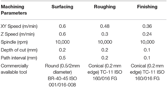
Table 1. Parameters used for green machining of ceramic blanks.
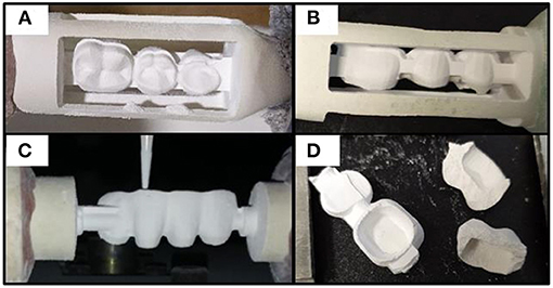
Figure 1. Soft machining of the dental bridge on computer numerical control (CNC) (A, B) molar, (C) incisor, and (D) failure during machining.
Binder Burnout and Sintering
After machining and finishing, the samples were fired in a high-temperature muffle furnace. The rate of heating was kept at 1.5°C/min until 550°C with a holding time of 2 h for binder burnout. Subsequently, the rate of heating was increased to 5°C/min until 1,000°C and 3°C/min until 1550°C with a holding time of 2 h at 1550°C for sintering. Sintered dental bridges are shown in Figure 2. Glazing was applied to the alumina bridge with a commercial dentine glaze procured from GC-Dental, America with the manufacturer-prescribed firing protocol. The physical appearance of the glazed surface was intact and has no visible cracks or delamination (Figure 2B).
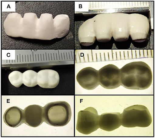
Figure 2. Dental bridges produced by CNC machining (A) sintered alumina incisor bridge, (B) after glazing, (C) sintered 3 yttria-stabilized zirconium oxide (YSZ) molar bridge, (D–F) stereo zoom microscopy in transmittance.
Characterization
MicroCT
MicroCT was performed using a 3D imaging system (GE phoenix v|tome|x, Germany) with a scanning resolution of 32 μm to evaluate the green sample and sintered samples made of 3YSZ. X-ray source voltage of 80 kV with a beam current of 70 mA for green samples and 150 mA for sintered samples were used. Beam current was optimized to match the density difference between green and sintered bodies. The size and morphology of the voids were analyzed using VGStudio MAX (Volume Graphics, Germany).
Precision and Shrinkage Analysis
Three-dimensional precision analysis/part comparison analysis was performed using software VG Studio Max (Volume Graphics, Germany), 3-Matic research 11.0, and CATIA V5 R19 to assess material homogeneity, shrinkage, and deviations during sintering that arise from warping or bending. The overall accuracy of this process in replicating the clinically acceptable marginal accuracy of the designed model without chipping of fine edges was assessed to analyze applicability in dental ceramics. The process essentially involves four steps (Figure 3).
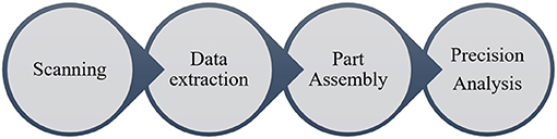
Figure 3. Flowchart for the procedure followed in the precision analysis.
➢ Scanning: micro-CT scans of machined and sintered parts.
➢ Data extraction: scanned CT images were extracted using Virtual Studio, and data were exported into STL format.
➢ Part assembly/matching: original, machined, and sintered component STL files were assembled, keeping the bottom cementation surface as a reference, utilizing CATIA V5 R19.
➢ Precision analysis: assembled parts were then analyzed in 3-Matic Research 11.0 software for overall 3D deviations.
Surface Profilometry
For optimizing the green machining parameters and analyzing the effect of path interval on final surface roughness, profilometry was performed for samples machined with different path intervals ranging from 0.05 mm to 0.4 mm with 0.05 mm increment. A contact profilometer of Taylor Hobson precision, Form Talysurf Series 2 with a conical tip, was used for the purpose. Measurement direction was maintained perpendicular to the direction of the tool path. Also, a 3D optical surface profilometer-Bruker, Model-Contour GT, with Vision 64 control and analysis software was used to generate a 3D surface mapping of the machined sample with optimized path interval to assess roughness before and after sintering.
X-ray Diffraction (XRD)
Phase analysis of the alumina and 3YSZ samples in green and sintered state was performed using an XRD pattern of a high-resolution X-ray diffractometer (Panalytica High-Resolution XRD-I, PW 3040/60) measured at 40 kV and 30 mA using Ni-filtered Cu Kα radiation (2θ = 10–80°). Intensity peaks of green and sintered samples were matched with the JCPDS file using the Xpert® analysis software.
Microstructure Analysis
A scanning electron microscope (Zeiss, Jena, Germany) was used to evaluate crystal size, morphology, and distribution on the machined surfaces of alumina and 3YSZ after sintering. In the bulk of the sample, defects and grain boundary distribution were evaluated on the fracture surface. The macrostructure of the sintered samples was examined with a stereo zoom microscope (Zeiss, Jena, Germany) to evaluate the machined features. The dust leftover after machining of the green samples was examined using a stereo zoom microscope in both reflectance and transmittance modes and compared with the dust from the machining of a partially sintered alumina blank, as shown in Figure 9.
Density and Hardness
The density of the green and sintered samples of alumina and 3YSZ in a water medium was evaluated using the Archimedes principle. Ten samples were randomly selected from extruded samples as well as machined samples after drying and sintering. Dry weight (w1) and wet suspended weight (w2) after 24 h soaking in vacuum were measured with a sartorius digital balance. Density was measured with the following equation:
… (1)
These values were converted to % theoretical density by assuming the theoretical density of alumina to be 3.95 ×10³ kg/m3 and that of 3 Mol% YSZ to be 6.05 ×10³ kg/m3.
Vickers hardness of the sintered alumina and 3YSZ was measured on the polished cross-sections of the samples using a diamond indenter with 200 gF.
Results and Discussion
MicroCT
Micro Computer Tomography (MicroCT) analysis of the alumina incisor bridge and 3YSZ molar bridge is shown in Figure 4. Both the images show a random distribution of pores with negligible pore volume (0.06 and 0.08% of the total volume). Tavares et al. reported a similar void analysis of commercially available sintered glass-reinforced ceramic blanks of IPS e.max and Rosetta SM CAD-CAM systems. They reported a porosity value of 0.05–0.1% for IPS e. max and 0.07–0.13% for Rosetta SM, with uniform pore distribution by MicroCT evaluation (17). The voids in this study could have formed during kneading or sintering and indicated the regions where powder distribution and packing were not homogeneous. The concentration of these voids would deteriorate the strength of the ceramic, especially when they are present in strategic areas such as thin contacts and edges between the teeth; however, in both the bridges, they are haphazardly distributed with two to three larger voids constituting 90% of the pore volume. In addition, they are aligned parallel to the occlusal plane, where the effect on the fracture toughness would be minimal. Since the blanks were prepared by molding the dough with low stress, the pores were remnant in the final body; however, while extruding the dough at higher stress, these voids could be minimized, and the green body could be void-free as discussed in a previous study (15).
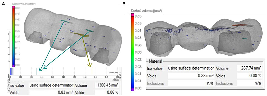
Figure 4. MicroCT void analysis of sintered (A) alumina incisor bridge, (B) 3YSZ molar bridge.
Precision and Shrinkage Analysis
Precision/tolerance analysis is performed after machining the bridge with respect to the reference surface file, as shown in Figure 5A, where the overall deviation is ranging between +0.52 and −0.79 mm. Slight deviation near the undercuts of buccal and lingual cuspal regions was inevitable because of the limitations with the three-axes machining and angular face cutting edges of the tools used; however, using the advanced five-axis CNC and automatic tool changing machines, which are specifically designed for use in clinical machining of pre-sintered or sintered ceramic blanks, these deviations could be further minimized. The shrinkage of 3YSZ blanks was studied separately, and the original model was scaled up before machining for compensating the shrinkage. The 3YSZ had shown anisotropic shrinkage of 16.5% in all directions. Overall dimensional tolerance between the original model and extracted surface file of the sintered model is shown in Figure 5B, where it can be observed that the deviation is in the range of +0.56–0.79 mm. In both tolerance studies, the cementation surface has shown minimal deviation in the range of −0.2–+0.2 mm, which is comparable with the clinically acceptable marginal accuracy of 0.1–0.2 mm with regard to longevity (18, 19). Warpage on edges and cusps during binder burnout and sintering of machined body, arising from non-homogeneous powder packing of the green body, could affect the marginal fitting on the prepared abutments. Hence, the tolerance between extracted surface files of the machined model and the scaled-up sintered model assuming 16.5% shrinkage is analyzed, as shown in Figure 5C. The precision was superior, with an overall deviation in the range of −0.25–+0.25 mm, while the deviation on the cementation surface and edges were in the range of −0.08–+0.08 mm. In addition, the deviation was uniform, representing homogeneous powder packing and minimal warpage. Hence, this technology can be safely adopted for the precise machining of the ceramic prosthesis in a dental laboratory. Rapid prototyping by stereolithography of zirconia slurry resulted in a zirconia core bridge with deviation in the range of −0.4–+0.4 mm (8). A good fitting of the cementation surface on the prepared tooth is crucial for minimizing micromotion, plaque accumulation, and increasing the longevity of the fixed restoration (20).
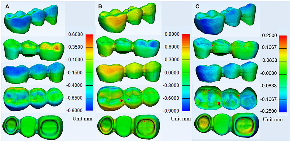
Figure 5. Precision analysis of YSZ bridge (A) reference file vs. machined file, (B) reference file vs. sintered file, and (C) machined file vs. sintered file assuming sintering shrinkage to be 16.5%.
Surface Profilometry
Figure 6 shows the contact roughness of sintered samples machined in a green state with different path intervals where it is evident that the average roughness (Ra) and root mean squared roughness (Rq) values were similar for path intervals from 0.05 to 0.2 mm. Upon further increasing the path interval, the roughness increased gradually from 0.25 to 0.35 mm interval. Beyond 0.35 mm, the roughness increased rapidly, which would result in an unacceptable surface finish both esthetically and functionally. Hence, a 0.2 mm path interval could be considered as the optimized parameter, which produces the best profile in the least possible time frame. Also, the conical tool used for roughing and finishing has an edge width of 0.2 mm, as shown in Table 1, which could be the cause of similar roughness until the 0.2 mm interval.
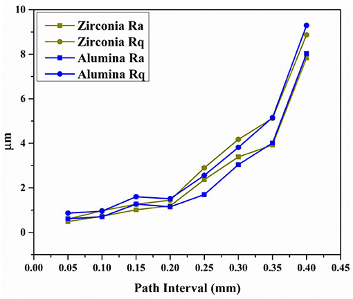
Figure 6. Contact surface profilometry of green machined samples with different path intervals after sintering.
The roughness for the green machined surface of alumina and 3YSZ with optimized path interval, pre and post-sintering, is evaluated with an optical profilometer, as shown in Figure 7. The surface roughness of both materials is compared, and the result has indicated that before sintering, the Ra values of the green machined surface for alumina and 3YSZ were 1.77 and 1.24 μm, respectively. After sintering, they increased to 2.46 and 2.24 μm, respectively. Correspondingly, the Rq values before sintering were 2.35 and 1.6 μm and increased to 3.33 and 3.07 μm, respectively, after sintering for alumina and 3YSZ. The Rq values represent the SD in the distribution of surface height measurements (21). The lower surface roughness of the green machined surface before sintering could be attributed to the presence of a binder between the particles and the smaller size of the un-sintered particles. Upon sintering the same surface, the roughness increased slightly because of the grain growth and binder burnout. Furthermore, these values are slightly higher than the roughness values measured with the contact profilometer, as shown in Figure 6. This could have arisen from the difference in resolution of probes, optical properties of the sintered material, and the area under measurement; however, the roughness values achieved after sintering with a 0.2 mm path interval using both methods are in good agreement with the literature by pre-sintered machining (22). They further suggest that a better shear bonding of the restoration with the luting resin cement would require a roughness value <3 μm. As the roughness increases, there is a tendency for void formation with decreased wetting of luting cement while flowing due to air inclusions (22).
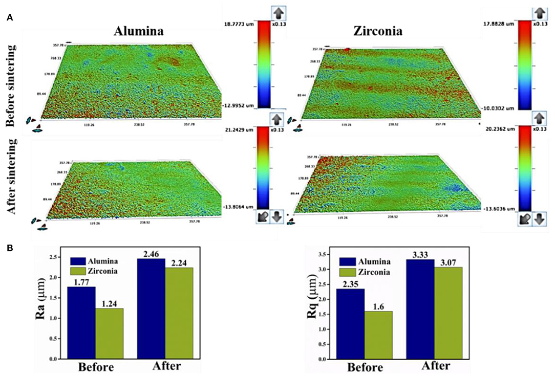
Figure 7. (A) Optical surface profilometry of green machined alumina and 3YSZ before and after sintering and (B) average roughness (Ra) and root mean squared (Rq) roughness, before and after sintering.
Occlusal surface with greater roughness would result in wear of antagonistic tooth. Zirconia restorations with roughness ~2.5–5 μm have resulted in a clinically simulated grinding and polishing study by Hmaidouch et al. (23). However, in this study, similar roughness was observed without any surface alteration after sintering. In this technique, the finishing parameters of green machining would also influence the sintered surface roughness. Hence, machining parameters were optimized with a focus on clinically acceptable surface finish in the least possible time frame. Roughness was also slightly higher on the alumina surface than the YSZ surface even though the machining parameters were the same in both, probably because of the difference in the particle size of starting powders. Along with roughness, the wettability of luting cement is also influenced by the presence of functional groups arising from etching treatment. Furthermore, physicochemical characteristics could clarify the influence of green machining on the shear bonding of bridges with luting cement.
X-ray Diffraction
The x-ray diffraction pattern of both alumina and 3YSZ samples in green and sintered states is shown in Figure 8. The alumina samples have α phase, and corresponding reflections on h k l lattice planes were mentioned. The peaks of the green sample were matching with that of the sintered samples, indicating that proper sintering and phase crystallization occurred without the formation of any unwanted phases; however, in the green 3YSZ sample, peaks corresponding to the monoclinic phase were prominent along with the tetragonal phase, whereas, after sintering, only tetragonal peaks were visible. This reveals that a beneficial tetragonal phase transformation has occurred during sintering, which is stable after cooling owing to yttria doping in the starting powder. Hence, it can be said that this novel dough processing did not affect or hinder the appropriate phase formation during processing.
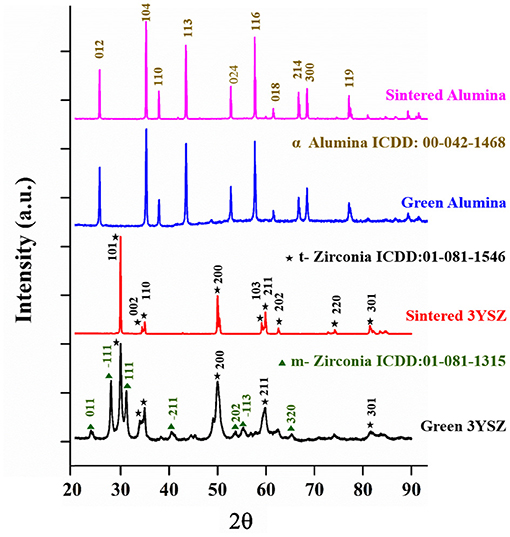
Figure 8. X-ray diffraction (XRD) analysis of green and sintered samples of alumina and 3YSZ.
Microstructure Analysis
Electron microscopy images of the sintered surfaces of alumina and 3YSZ produced by green machining were examined for topography and the presence of voids and defects, and evaluation of crystallite size, grain morphology, and grain size distribution (Figure 9). It is evident that the prominent types of brittle surface damages associated with sintered body machining, such as grain chipping and inter- and intra-granular defects, were absent in the green machined surface. During machining of sintered surface, preventing the formation of these cracks with a ductile removal mechanism requires highly controlled machining with a very low critical cutting depth and removal rate using ultra-speed tools in the presence of a coolant (24). All these factors invariably increase the cost of the machined component; however, in the present process, the parameters and the tools used, as shown in Table 1, were not very demanding yet successfully produced a high-quality surface finish after sintering.
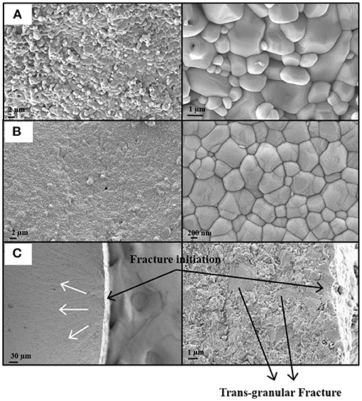
Figure 9. Scanning electron microscopy (SEM) images of sintered surface (A) alumina green machined, (B) 3YSZ green machined, and (C) fractured 3YSZ (crack propagation pattern in white arrow).
The alumina surface demonstrates elongated coarse grains, which are crack-stable. In addition, it has a combination of fine as well as elongated grains that might add to the strength and contribute toward stable crack-free alumina (25). The absence of voids, as observed in the bulk of the sintered 3YSZ, could be attributed to superior densification that occurred during the sintering step, and the average grain size of ~ 826 nm was achieved. The zirconia fracture pattern from the crack initiation point (9.c white arrow) reveals that the crack propagated because of forced rupture from bending where both grains pullout and trans-granular fractures were observed.
Stereo zoom microscopy of the machined dust in the green and partially sintered state, as shown in Figure 10, reveals that green machining resulted in very fine dust compared with partially sintered machining. Hence, less force would be required by tools for particle removal without compromising feed rate during machining. In general, green samples by slurry casting or hot isostatic pressing tend to be hard with local heating and chipping during machining. However, the green body in this study has a soft vinyl polymer adhesive and a lubricant coating the particles, resulting in reduced hardness without compromising the green strength. Consequently, the abrasiveness of ceramic particles would also be reduced, increasing tool life significantly. Also, it was observed that the green debris can be reused without post-processing to break down agglomerates. Addition of solvent and repeating the dough process would be sufficient to obtain similar dough quality, suggesting that the binder and lubricant coating were unaltered during machining. This would further reduce wastage and make the product affordable, especially in dental ceramics, where rear earth materials, such as zirconia, are preferred. It also explains the finding that the force required for particle removal was minimal. When greater force is applied during tooling, it results in a localized rise in temperature, degrading the polymer binders.
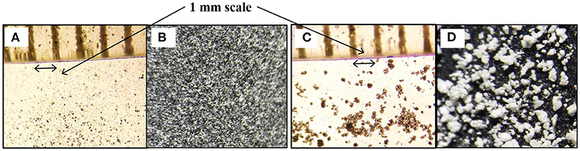
Figure 10. Stereo zoom microscopy at 4X of (A, B) dust from alumina machining and (C, D) green dust partially sintered in transmittance and reflectance modes.
Furthermore, the tools used for machining are examined with the microscope (Figure 11) along with an unused one. The roughing and finishing tool used for machining green samples for ~4 h retained its edge sharpness and diamond coating, whereas the bur used for roughing a partially sintered alumina blank for just ~ 30 min lost its tip and diamond coating. A good quality tip is crucial for proper edge retention and successful green machining, as it is found that failure during green machining (Figure 1D) mostly occurs when the tool has lost its cutting edge (Figure 11). Blunting of cutting edge and loss of diamond coating result in increased surface roughness, high-frequency vibrations, and greater dynamic forces with localized heating in the blank, failing machining (26, 27). It is to be noted that the tools used in this study may not be intended for a ceramic machining purpose and that many advanced tools with long life and efficiency are available. However, we intended to emphasize the ease and minimal force required for machining the dried green blanks produced by this novel dough technique.
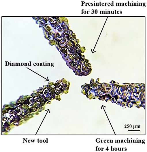
Figure 11. Stereo zoom microscopy at 5X of tools after green and pre-sintered machining along with new tool (indicates the removal of the diamond coating during machining of partially sintered alumina).
Density and Hardness
The apparent green body density of the alumina and YSZ achieved was 68.8 ± 1 and 57.4 ± 0.9, respectively. After sintering, the apparent density attained was 97 ± 1.2 and 97 ± 2.1 for alumina and YSZ, respectively. In both cases, the green body apparent density was considerably higher than that of the previous reports (13, 28, 29). A high green density results in uniform shrinkage and minimal defects in the components after sintering. Machining of the dense green body produces a smooth surface contour with good resolution and edge retention. This can be observed in the MicroCT analysis discussed above where the calculated pore volume was negligible. The hardness of the sintered alumina and 3YSZ measured by the Vickers indenter, using 200 gF is shown in Table 2. These results also match with those reported for dental ceramics made of alumina, 3YSZ and their composites (8, 30, 31).
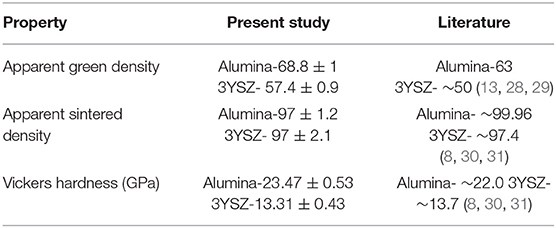
Table 2. Representation of measured values of density and hardness in this study compared with those in the literature.
Flexural strength and Weibull analysis was performed in the previous study, where the three-point flexural strength of the extruded alumina and YSZ achieved was 408.3 ± 61.47 MPa and 690.5 ± 51.5 MPa, respectively (15). The Weibull analysis on the flexural strength of sintered alumina resulted in modulus 5.4 with the scale parameter of 404.6 MPa, whereas for Zirconia, the modulus is 10.02 with the scale parameter of 665.17 Mpa (15). The green body hardness of both dried blanks, as measured by nanoindentation, was 0.3 ± 0.1 Mpa, and the three-point flexural strength was 5.3 ± 0.8 Mpa. In the case of YSZ, the strength was inferior to the commercially available dental zirconia, which usually employs additives to control grain growth and improve strength (32, 33). In addition, final strength depends on the interplay of different processing parameters, such as sintering time, temperature, doping, and grain size distribution. Further, both the alumina and YSZ processed by this dough process as presented in the previous study showed strength greater than those reported for ceramics used in dental restorations (34, 35). The longevity of a dental restoration under constant cyclic loading and a complex set of masticatory forces is influenced by fatigue in the prosthesis. In addition, the presence of moisture and an acidic oral environment degrades the strength in zirconia ceramics because of the low-temperature degradation effect (36, 37). Hence, cyclic loading in simulated oral fluids would give a clear understanding of the stability of these monolith bridges.
Conclusion
Full-contour monolith dental bridges of alumina and YSZ were soft machined on a dried green body with good replication of fine details after sintering. Three-dimensional surface profile mapping with optimized machining parameters revealed a smoother green machined surface with a roughness of 1.2–1.7 μm, while after sintering it increased to 2.2–2.4 μm. Glazing for an improved esthetic appearance with a commercial dental glaze was also successful on an alumina bridge without any visible cracks or delamination. The precision analysis of the molar bridge after sintering resulted in a clinically acceptable tolerance limit of ±200 μm marginal fitting on the cementation surface. The strength and hardness of the components produced through this novel technique were also in agreement with the reported values. Microscopy of the tools after green machining revealed an extended life of the cutting edge compared with the routinely employed pre-sintered machining, owing to a negligible surface hardness of the dried ceramic blank.
Data Availability Statement
The original contributions presented in the study are included in the article/supplementary material, further inquiries can be directed to the corresponding author/s.
Author Contributions
VS: Conceptualization, methodology, experimental, writing-original draft, and review and editing. BP: Conceptualization and editing. SJ: Experimental. AO and RR: Experimental and writing. PV: Experimental, analysis, and writing. SD: Supervision, conceptualization, resources, formal analysis, and writing-review and editing. All authors contributed to the article and approved the submitted version.
Conflict of Interest
The authors declare that the research was conducted in the absence of any commercial or financial relationships that could be construed as a potential conflict of interest.
Publisher's Note
All claims expressed in this article are solely those of the authors and do not necessarily represent those of their affiliated organizations, or those of the publisher, the editors and the reviewers. Any product that may be evaluated in this article, or claim that may be made by its manufacturer, is not guaranteed or endorsed by the publisher.
Acknowledgments
The authors wish to thank the Ministry of Human Resource and Development (MHRD), the Government of India, the Defense Research and Development Organization (DRDO), and the Indian Institute of Technology Kharagpur, India, for supporting this study.
References
1. Filser F, Kocher P, Gauckler L. Net-shaping of ceramic components by direct ceramic machining. Assembly Autom. (2003) 23:382–90. doi: 10.1108/01445150310501217
2. Ebeid K, Wille S, Hamdy A, Salah T, El-Etreby A, Kern M. Effect of changes in sintering parameters on monolithic translucent zirconia. Dental materials. (2014) 30:e419–24. doi: 10.1016/j.dental.2014.09.003
3. Torabi K, Farjood E, Hamedani S. Rapid prototyping technologies and their applications in prosthodontics, a review of literature. J Dent. (2015) 16:1.
4. Fraga S, Amaral M, Bottino MA, Valandro LF, Kleverlaan CJ, May LG. Impact of machining on the flexural fatigue strength of glass and polycrystalline CAD/CAM ceramics. Dental Materials. (2017) 33:1286–97. doi: 10.1016/j.dental.2017.07.019
5. Zhang Y, Lawn BR. Fatigue sensitivity of Y-TZP to microscale sharp-contact flaws. J Biomed Mater Res B: Appl Biomater. (2005) 72:388–92. doi: 10.1002/jbm.b.30174
6. Zucuni C, Guilardi L, Fraga S, May L, Pereira G, Valandro L. CAD/CAM machining Vs pre-sintering in-lab fabrication techniques of Y-TZP ceramic specimens: Effects on their mechanical fatigue behavior. J Mech Behav Biomed Mater. (2017) 71:201–8. doi: 10.1016/j.jmbbm.2017.03.013
7. Faes M, Valkenaers H, Vogeler F, Vleugels J, Ferraris E. Extrusion-based 3D printing of ceramic components. Procedia Cirp. (2015) 28:76–81. doi: 10.1016/j.procir.2015.04.028
8. Lian Q, Sui W, Wu X, Yang F, Yang S. Additive manufacturing of ZrO2 ceramic dental bridges by stereolithography. Rapid Prototyping J. (2018) 24:114–19. doi: 10.1108/RPJ-09-2016-0144
9. Chen F, Wu J-M, Wu H-Q, Chen Y, Li C-H, Shi Y-S. Microstructure and mechanical properties of 3Y-TZP dental ceramics fabricated by selective laser sintering combined with cold isostatic pressing. Int J Lightweight Mater Manufacture. (2018) 1:239–45. doi: 10.1016/j.ijlmm.2018.09.002
10. Ackerl N, Warhanek M, Gysel J, Wegener K. Ultrashort-pulsed laser machining of dental ceramic implants. J Eur Ceram Soc. (2019) 39:1635–41. doi: 10.1016/j.jeurceramsoc.2018.11.007
11. Lauwers B, Klocke F, Klink A, Tekkaya AE, Neugebauer R, Mcintosh D. Hybrid processes in manufacturing. CIRP Annals. (2014) 63:561–83. doi: 10.1016/j.cirp.2014.05.003
12. Hong Y, Lei J, Heim M, Song Y, Yuan L, Mu S, et al. Fabricating ceramics with embedded microchannels using an integrated additive manufacturing and laser machining method. J Am Ceram Soc. (2019) 102:1071–82. doi: 10.1111/jace.15982
13. Liao J, Zhang D, Wu X, Luo H, Zhou K, Su B. Preparation of high strength zirconia by epoxy gel-casting using hydantion epoxy resin as a gelling agent. Mater Sci Eng C. (2019) 96:280–5. doi: 10.1016/j.msec.2018.11.023
14. Venkata Sundeep Seesala S. D. A green body composition and functional gradient material prepared thereof. Indian Patent- 201931022298 WO 2020/245645 A1 Dated 10 December 2020.
15. Venkata Sundeep Seesala S. D. Nature inspired dough processing for alumina-zirconia composites: rheology plasticity and weibull analysis towards net shape forming. J Eur Ceram Soc. (2021) doi: 10.1016/j.jeurceramsoc.2021.07.019
16. GRABCAD. Available online at: https://grabcad.com/library?page=1&time=all_time&sort=recent&query=molar.
17. Tavares LD, Zancopé K, Silva AC, Raposo LH, Soares CJ, Neves FD. Microstructural and mechanical analysis of two CAD-CAM lithium disilicate glass-reinforced ceramics. Braz Oral Res. (2020) 34. doi: 10.1590/1807-3107bor-2020.vol34.0004
18. Boening KW, Wolf BH, Schmidt AE, Kästner K, Walter MH. Clinical fit of Procera AllCeram crowns. J Prosthet Dent. (2000) 84:419–24. doi: 10.1067/mpr.2000.109125
19. Fransson B, Øilo G, Gjeitanger R. The fit of metal-ceramic crowns, a clinical study. Dental Mater. (1985) 1:197–9. doi: 10.1016/S0109-5641(85)80019-1
20. Hasti A, Patil NP. Investigation of marginal fit and surface roughness of crowns, due to different bench set and different burnout temperature using base metal alloy. The J Indian Prosthodontic Soc. (2010) 10:154–9. doi: 10.1007/s13191-010-0024-y
21. Gadelmawla E, Koura MM, Maksoud TM, Elewa IM, Soliman H. Roughness parameters. J Mater Process Technol. (2002) 123:133–45. doi: 10.1016/S0924-0136(02)00060-2
22. Lopes FC, Palma-Dibb RG, Campi LB, Roselino RF, Gomes ÉA, Canevese VA, et al. Surface topography and bond strength of CAD–CAM milled zirconia ceramic luted onto human dentin: effect of surface treatments before and after sintering. Appl Adhes Sci. (2018) 6:1–11. doi: 10.1186/s40563-018-0110-7
23. Hmaidouch R, Müller W-D, Lauer H-C, Weigl P. Surface roughness of zirconia for full-contour crowns after clinically simulated grinding and polishing. Int J Oral Sci. (2014) 6:241–6. doi: 10.1038/ijos.2014.34
24. Bukvic G. Sanchez LEdA, Fortulan CA, Fiocchi AA, Marinescu ID. Green machining oriented to diminish density gradient for minimization of distortion in advanced ceramics. Mach Sci Technol. (2012) 16:228–46. doi: 10.1080/10910344.2012.673968
25. Kovar D, Bennison SJ, Readey MJ. Crack stability and strength variability in alumina ceramics with rising toughness-curve behavior. Acta Mater. (2000) 48:565–78. doi: 10.1016/S1359-6454(99)00350-X
26. Bian R, Ferraris E, He N, Reynaerts D. Process investigation on meso-scale hard milling of ZrO2 by diamond coated tools. Precis Eng. (2014) 38:82–91. doi: 10.1016/j.precisioneng.2013.07.007
27. Cho S-S, Komvopoulos K. Correlation between acoustic emission and wear of multi-layer ceramic coated carbide tools. (1997) 119:238–46. doi: 10.1115/1.2831100
28. Liu G, Attallah MM, Jiang Y, Button TW. Rheological characterization and shape control in gel-casting of nano-sized zirconia powders. Ceram Int. (2014) 40:14405–12. doi: 10.1016/j.ceramint.2014.06.036
29. Mohanty S, Rameshbabu AP, Dhara S. Net shape forming of green alumina via CNC machining using diamond embedded tool. Ceram Int. (2013) 39:8985–93. doi: 10.1016/j.ceramint.2013.04.099
30. Fan J, Lin T, Hu F, Yu Y, Ibrahim M, Zheng R, et al. Effect of sintering temperature on microstructure and mechanical properties of zirconia-toughened alumina machinable dental ceramics. Ceram Int. (2017) 43:3647–53. doi: 10.1016/j.ceramint.2016.11.204
31. Ghanizadeh S, Grasso S, Ramanujam P, Vaidhyanathan B, Binner J, Brown P, et al. Improved transparency and hardness in α-alumina ceramics fabricated by high-pressure SPS of nanopowders. Ceramics International. (2017) 43:275–81. doi: 10.1016/j.ceramint.2016.09.150
32. Pittayachawan P, McDonald A, Petrie A, Knowles JC. The biaxial flexural strength and fatigue property of Lava™ Y-TZP dental ceramic. Dental Mater. (2007) 23:1018–29. doi: 10.1016/j.dental.2006.09.003
33. Xu Y, Han J, Lin H, An L. Comparative study of flexural strength test methods on CAD/CAM Y-TZP dental ceramics. Regenerative Biomater. (2015) 2:239–44. doi: 10.1093/rb/rbv020
34. Lohbauer U, Petschelt A, Greil P. Lifetime prediction of CAD/CAM dental ceramics. J Biomed Mater Res. (2002) 63:780–5. doi: 10.1002/jbm.10468
35. Nishioka G, Prochnow C, Firmino A, Amaral M, Bottino MA, Valandro LF. Fatigue strength of several dental ceramics indicated for CAD-CAM monolithic restorations. Braz Oral Res. (2018). 32. doi: 10.1590/1807-3107bor-2018.vol32.0053
36. Kohorst P, Borchers L, Strempel J, Stiesch M, Hassel T, Bach F-W, et al. Low-temperature degradation of different zirconia ceramics for dental applications. Acta Biomater. (2012) 8:1213–20. doi: 10.1016/j.actbio.2011.11.016
Keywords: ceramic dough, monolith dental bridge, zirconia, alumina, CNC, soft machining
Citation: Seesala VS, Vaidya PV, Rajasekharan R, Kumar Ojha A, Jana S, Pal B and Dhara S (2021) Monolith Dental Bridge by Soft Machining of Dried Ceramic Dough. Front. Dent. Med. 2:663219. doi: 10.3389/fdmed.2021.663219
Received: 02 February 2021; Accepted: 12 July 2021;
Published: 13 August 2021.
Edited by:
Bo Su, University of Bristol, United KingdomReviewed by:
Edouard Rivière, University of Mons, BelgiumFrançois Ducobu, University of Mons, Belgium
Copyright © 2021 Seesala, Vaidya, Rajasekharan, Kumar Ojha, Jana, Pal and Dhara. This is an open-access article distributed under the terms of the Creative Commons Attribution License (CC BY). The use, distribution or reproduction in other forums is permitted, provided the original author(s) and the copyright owner(s) are credited and that the original publication in this journal is cited, in accordance with accepted academic practice. No use, distribution or reproduction is permitted which does not comply with these terms.
*Correspondence: Santanu Dhara, c2RoYXJhQHNtc3QuaWl0a2dwLmFjLmlu