 Shengqi Yu1*
 Thanasin Bunnam1,2
 Sirichai Triamlumlerd2
 Manoch Pracha2
 Fei Xia1
 Rishad Shafik1*Alex Yakovlev1*
- 1Microsystems Group, School of Engineering, Newcastle University, Newcastle Upon Tyne, United Kingdom
- 2Department of Computer Engineering, Faculty of Engineering, Rajamangala University of Technology Thanyaburi, Pathum Thani, Thailand
Artificial intelligence applications implemented with neural networks require extensive arithmetic capabilities through multiply-accumulate (MAC) units. Traditional designs based on voltage-mode circuits feature complex logic chains for such purposes as carry processing. Additionally, as a separate memory block is used (e.g., in a von Neumann architecture), data movements incur on-chip communication bottlenecks. Furthermore, conventional multipliers have both operands encoded in the same physical quantity, which is either low cost to update or low cost to hold, but not both. This may be significant for low-energy edge operations. In this paper, we propose and present a mixed-signal multiply-accumulate unit design with in-memory computing to improve both latency and energy. This design is based on a single-bit multiplication cell consisting of a number of memristors and a single transistor switch (1TxM), arranged in a crossbar structure implementing the long-multiplication algorithm. The key innovation is that one of the operands is encoded in easy to update voltage and the other is encoded in non-volatile memristor conductance. This targets operations such as machine learning which feature asymmetric requirements for operand updates. Ohm’s Law and KCL take care of the multiplication in analog. When implemented as part of a NN, the MAC unit incorporates a current to digital stage to produce multi-bit voltage-mode output, in the same format as the input. The computation latency consists of memory writing and result encoding operations, with the Ohm’s Law and KCL operations contributing negligible delay. When compared with other memristor-based multipliers, the proposed work shows an order of magnitude of latency improvement in 4-bit implementations partly because of the Ohm’s Law and KCL time savings and partly because of the short writing operations for the frequently updated operand represented by voltages. In addition, the energy consumption per multiplication cycle of the proposed work is shown to improve by 74%–99% in corner cases. To investigate the usefulness of this MAC design in machine learning applications, its input/output relationships is characterized using multi-layer perceptrons to classify the well-known hand-writing digit dataset MNIST. This case study implements a quantization-aware training and includes the non-ideal effect of our MAC unit to allow the NN to learn and preserve its high accuracy. The simulation results show the NN using the proposed MAC unit yields an accuracy of 93%, which is only 1% lower than its baseline.
1 Introduction
Arithmetic operations are central to modern artificial intelligence applications implementing neural networks (NNs) (Park et al., 2018; Shafik et al., 2018). In these operations, multiplication plays a crucial role with significant impact on performance and energy efficiency, especially because traditional multiplier circuits feature complex partial product generation and carry propagation logic chains (Qiqieh et al., 2018). As such, reducing the energy consumption of multipliers, when used in NNs, is an ongoing design challenge.
For low-complexity multiplication, reducing precision is a viable method. For this, pruning the carry chains to a minimum proportion while also maintaining an acceptable precision has been proposed by numerous approximate and speculative circuit designs (Cilardo et al., 2014). However, these designs require careful synergy of operating voltages and frequencies to balance energy and performance trade-offs (Shafik et al., 2016). Moreover, the accumulation of imprecision and errors in cascaded workloads needs mitigation strategies which adds more complexity to the logic chains (Yakovlev, 2015). Consequently, the usability of voltage-mode proportional carry pruning schemes is still limited. On the other hand, using multipliers with very low precision may be a viable solution for certain applications. For instance, multipliers with 4-bit precision have been shown to be useful for machine learning applications (Chahal, 2019), including deep learning with datasets of significant sizes and complexity (Sun et al., 2020) and targeting datasets more relevant for mobile applications at the edge (Trusov et al., 2021). In this paper we target the design and implementation of low-precision MACs for low-energy edge applications.
Another problem with using existing arithmetic methods is related to the approach of running AI software on conventional computers based on von Neumann or Harvard architectures (Zheng and Mazumder, 2019). Machine learning using NNs and other AI methods involves multiple iterations of arithmetic operations with data flow between processing elements and memory being a significant bottleneck for conventional computers (Zheng and Mazumder, 2019; Fujiki et al., 2021). In-memory computing, especially using non-volatile memory technologies may provide ways of reducing the amounts of data flow required for AI applications including NNs (Fujiki et al., 2021; Hung et al., 2021). Additionally, the non-volatile property of memories can reduce the number of data movements, even when the computing system sustains power cuts or interruptions.
Recently mixed-signal multiplier designs based on non-volatile memory (memristor cells) have been proposed (Yu et al., 2021), where the operands are expressed in multiple modes, e.g., voltage, conductance and current. Single-bit multiplication for partial product terms is performed in current mode, which naturally follows Ohm’s law. In this mode, the voltage input and conductance represent the two operands and the resulting current represents the output. Multiple partial product terms can be accumulated using Kirchhoff’s Current Law (KCL) by organizing the single-bit cells in a crossbar structure. With KCL, addition and subtraction are, respectively equivalent to joining multiple current paths into a node and removing current paths from a node.
This type of mixed-signal multiplier is digital-in/analog-out. Because transistor switching happens when setting the memristor values and connecting the input voltages, a delay is associated with making the operands (multiplier and multiplicand) ready. After that, the single-bit multiplication operation itself only involves resistive Ohm’s Law which can be regarded as instantaneous. This means that the partial products are immediately obtained once the operands are ready. The addition of partial products through KCL across the crossbar requires current amplification and has a delay associated solely with the amplifiers. These current amplifiers can be implemented with current mirrors, in which case there is transistor-related delays. However, they may also be implemented with memristor cell topologies in a pure resistive fashion, again achieving negligible delay. This compares to regular digital schemes which have to go through multi-stage addition and carry-handling operations with a substantial number of transistor switchings once the bit products appear (Yu et al., 2021). In this paper we use the second method to drastically reduce multiplication delay, which results in significant reductions in energy per operation.
Another advantage of such transistor-memristor crossbar multipliers is that one of the operands is represented by memristor conductance
On the other hand, for multi-stage operations such as NNs in a non Von Neumann neuromorphic architecture (Zheng and Mazumder, 2019), a digital-in/digital-out MAC unit is required. If this type of mixed-signal multiplier is to be used, additional circuits are needed to generate the appropriate digital output from the intermediate current which encodes the product.
Memristor-based digital multipliers exist in the literature (Guckert and Swartzlander, 2017) and these will be comparatively studied with our method in the paper (in e.g., Section 6.1).
This paper describes a novel MAC unit based on mixed-signal multipliers using transistor-memristor cells on crossbar intersections. In this design, one operand is encoded in voltages for frequent value updates and the other is encoded in memristor conductance values for infrequent value updates. The intermediate products are represented by currents. By representing binary values with high and low values of these analog parameters and signals, the multipliers implement bit multiplication through Ohm’s Law and the summation of partial products through KCL, combining both steps into the long multiplication algorithm. The intermediate current product is then converted to voltage-encoded multi-bit digital format. Targeting multi-MAC applications such as NNs, there is a built-in bit-precision reduction which makes the output the same bit resolution as the inputs, unlike typical digital multipliers which have double the number of bits in their products compared with the operands. These techniques combine to reduce the latency per multiplication for our method compared with existing memristor-based multipliers, and the latency reduction in turn causes a reduction in the energy consumption. Our main contributions are:
• Developing a high energy efficiency end-to-end multiplication accumulation unit based on the transistor-memristor crossbar multiplier with mode transition for such applications as classification NNs.
• Developing optimization methods such as the elimination of current mirrors by changing the topologies of memristor cells and investigating different memristor technologies resulting in an order of magnitude improvements in accuracy, speed and energy.
• Demonstrating the advantages of our multipliers over existing designs through extensive theoretical and experimental investigations.
• Validating the MAC design by using it as a perception in a non Von Nuemann neural network implementation with quantization-aware training solving an example machine learning problem of a size relevant for low-energy edge applications (MNIST hand-writing classification).
The rest of the paper is organized as follows: Section 2 describes the research baseline and technological foundations, and discusses existing related work. Section 3 presents the first of our MAC unit designs, based on the memristor multiplication cell. Section 4 describes component and circuit implementation details, and explores different multiplication cell designs in an extensive comparative study, validating the advantages of our multiplier design method on all major fronts. Section 5 presents a machine learning case study with the proposed MAC acting as perceptrons in an MLA NN. Section 7 then concludes the paper.
2 Background
The memristor, proposed by Chua as the fourth element in the charge and flux taxonomy (Chua, 1971), has a number of promising characteristics. One of these is its potential in replacing semiconductor components in processing circuits. That is because, as a switchable device, a memristor can perform similar ON-OFF operations to a transistor with adjustable doped/undoped regions, which turn memristor to ON/OFF states (See Figure 1). This became more significant when practical memristor implementation examples appeared (Strukov et al., 2008; Radwan et al., 2012). As a nonvolatile component, the memristor has been used in memory device design, which is now called “resistive memory” (Ho et al., 2009). At the same time, the possibilities for performing arithmetic with memristors have also been explored, with multiplication being viewed as especially promising (Reid, 2009). Memristor cell methods have also featured in complex logic calculations such as “material implication” (IMP) (Borghetti et al., 2010). Computation processing units based on memristors have been designed for multiple applications, such as signal processing, artificial intelligence training, hardware acceleration, and encoding/decoding (Gupta et al., 2016; Krestinskaya et al., 2020). All these have multiply-accumulate operation at the centre, for which the memristor unit is well suited.
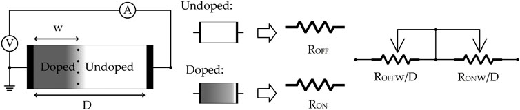
FIGURE 1. Memristor structure and component details. Memristor resistance depends on the with of doped/undoped region, the region width changed by the electrical potential difference on the component terminals, if over threshold, the higher potential terminal will extend respective region width.
The crossbar structure has been used to implement, in a straightforward manner, various types of multiplication including matrix multiplication (Li et al., 2018) and Shift-and-Add multiplication (Guckert and Swartzlander, 2017). The transistor-memristor pair has shown high precision in controlling operations, making it useful in large scale circuits, demonstrating high potential in performance, efficiency, and latency (Chen et al., 2019). One transistor one memristor (1T1M) was also favourably compared with Wallace-tree methods and conventional CMOS approach for the same metrics (Yu et al., 2020b). A crossbar multiplier approach with one transistor multiple memristor (1TxM) cells additionally demonstrated higher precision (Yu et al., 2020a). Space taken by the 1TxM cell may be reduced by merging memristors with higher margin values (Yu et al., 2021).
In (Yu et al., 2021), on which this paper is partially based, a memristor-cell crossbar structure implements both the single-bit multiplication at each cell. This is followed by the addition part of multi-bit multiplication algorithm across the crossbar with significance-related current amplification for different bit positions so that the total summed current corresponds to the correct final product for output. A crossbar multiplier is potentially an area-saving solution because the memristor crossbar can be built on top of the transistor-related layers using a back-end-of-line process (Constantoudis et al., 2019). Therefore, the area can be smaller than that used by the traditional CMOS multiplier.
Several designs of memristor cells have been proposed in the literature. Example cell structures include the single memristor (1M) cell, the multiple memristor (xM) cell, the single transistor single memristor (1T1M) cell, and single transistor multiple memristor (1TxM) cell. These designs focus on generating different combinations of memristor resistance (RM) for respective memristor conductance (DM) to achieve target arithmetic expressions. Usually, logic operation on a memristor is achieved by adjusting the voltage across it. A crossbar based on 1M cells cannot provide the correct currents for digits of different significance without additional current multiplication, usually with current mirrors. The xM-cell crossbar is able to generate the required output current without additional circuits (Yu et al., 2020b).
Moreover, current amplification is necessary in a crossbar mixed-signal multi-bit multiplier where current represents product. With each cell producing a current representing the value of Boolean 0 or 1, KCL can only work to produce a total current representing the multi-bit product if the current value at any bit position is amplified correctly according to the bit’s value significance. In other words, any bit should be twice the value of the bit to its right. This is conventionally implemented with a current-mirror-based current amplifier at each bit on 1M cell crossbar. By tuning the output transistor size in a current mirror, a bit’s correct significance can be set. However, this scheme results in extra area cost from potentially very large transistors. In addition, power and latency requirements of large transistors in current mirrors also limit system efficiency and performance (Yuan, 2006).
Taking advantage of memristor resistivity, the resistive xM cell can perform amplification by adjusting cell RM for the target operand. The most straightforward method is to keep single-memristor resistances the same across the multiplier, but build 1TxM cells with different numbers (x values) of parallel memristors corresponding to their bit significances. For instance, we may use 1M for bit 0, 2M for bit 1, 4M for bit 2, 8M for bit 3, etc. In this way, the cells perform the required current amplification, removing the need for current mirrors. When applied to the crossbar architecture, both 1M and xM cells help reduce the energy cost and latency. Meanwhile, the space cost of multipliers based on these cells can also be lower (Li et al., 2018).
3 Multiply and accumulation unit
Our MAC unit consists of memristor-transistor crossbar multiplier and mixed-signal Flash analog to digital converter (ADC) Which is show in Figure 2. In this section, the main parts of this MAC unit will be introduced.
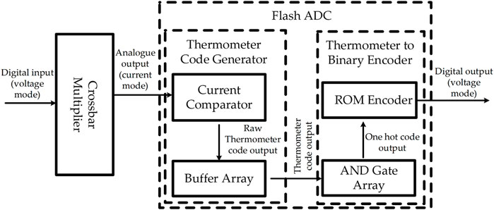
FIGURE 2. MAC units structure.
3.1 Transistor-memristor crossbar multiplier
3.1.1 Memristor
Decades after the inception of the memristor, in addition to the general mathematical model, analog behavioral models (ABM) were also developed for deeper research on memristor characteristics in circuits. The linear ion drift model was first developed from the basic memristive definition of memristor current-voltage relationship. This model uses the current-control method to adjust doped region width for changing memristor resistance (Strukov et al., 2008). However, the ideal assumption that the doped region width changes linearly is unrealistic, especially, undesirable for logic circuits.
As a result, with assistance of window function to regulate relation between physical device size and resistance variation, the nonlinear ion drift model attempts to represent the complexity of fabricated memristive device state drift (Lehtonen and Laiho, 2010). As early stage models, both the linear ion drift model and the nonlinear ion drift model offer low accuracy for the building of oxide region and doped oxide region like two series connected resistors. Aiming at building a more realistic model, a more accurate physical model is built by connecting an electron tunnel barrier with a resistor in series.
This one is called the Simmons tunnel barrier model, it shows a relatively high level of accuracy among TiO2 memristive device at the same level of complexity (Berdan et al., 2014). To balance accuracy and complexity, Kavatinsky makes a simplification about the physical behavior and mathematical functions complexity in the Simmons tunnel barrier model, then the threshold adaptive memristor model (TEAM) is generated with a reasonable balance between accuracy performance and computational efficiency (Kvatinsky et al., 2013). Since the existence of the threshold voltage is found from memristive devices, Kavtinsky updated ABM TEAM to voltage threshold adaptive memristor (VTEAM) (Kvatinsky et al., 2015). As a threshold-based voltage-driven model, VTEAM combines the advantage of the TEAM model with multiple freely chosen current-voltage characteristics. This helps to precisely estimate all reported physical device behaviours, such as linear ion drift (Strukov et al., 2008), nonlinear ion drift (Lehtonen and Laiho, 2010) and the Simmons tunnel barrier (Berdan et al., 2014), yet it exhibits superior computation efficiency especially for memory and logic applications (Kvatinsky et al., 2015; Singh et al., 2016). This paper makes use of the VTEAM memristor model in design and analysis.
3.1.2 Memristor-transistor multiplication cell
In Figure 3, the single-bit multiplication cell is represented. The serial connection of multiple memristors (xM) and multiple transistors (yT) generates the basic multiplication cell in the proposed multiplier.
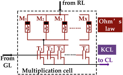
FIGURE 3. yTxM multiplication cell structure.
A memristor can be set in two interchangeable states: high conductance state (HCS) and low conductance state (LCS). These two states are used to represent the value on one of the two single-bit operands (inputs). When providing/preparing the value of this operand, the cell works in writing mode, with the input voltage used to write either HCS or LCS into the memristor. After this operand is set, the cell can work in reading mode, which is the multiplication operation. In reading mode, the input voltage takes the value of the other operand and is in either of the two states: high voltage state (HVS) and low voltage state (LVS). The cell current then forms the output (product) of the single-bit multiplication according to Ohm’s law, and is also in Boolean format with high and low states. The transistors additionally serves the purpose of turning the cell off (not writing and not reading, but holding the operand encoded in the memristor conductance state). Representing both operands with memristor parameters, however, reduces the usefulness of the multiplier because of the writing cycle limitations of memristors (Khan et al., 2021). Millions of writing cycles are appropriate for a slow changing operand such as a control system coefficient or a weight parameter in machine learning, but far from enough for the fast changing values multiplied by them. A scheme with asymmetric non-volatility is therefore needed.
Therefore, the operation of multiplication cell can be easily used to encode Boolean logic: HCS and HVS represent logic 1, LCS and LVS represent logic 0. Similarly, the output current also has high and low states which can encode logic 1 and logic 0. In this way, a memristor-transistor cell can perform single bit multiplication (same as logic AND).
3.1.3 Crossbar multiplier
Single-bit multiplication cells are then composed into a multi-bit multiplier using a crossbar structure, with KCL taking charge of the partial product addition step. A 4-bit case can be seen in Figure 4. In this figure, all single-bit multiplication cells are included in the Ohm’s law zone (marked in brown dashed lines). On the other hand, all wires and nodes through which currents flow belong to the KCL zone, marked in purple dashed lines. In the KCL zone, nodes “Digit1” to “Digit7” represent partial products while the current through the load resistor Rout is the final product. Note that, unlike the common long-multiplication algorithm, there is no attempt at finding horizontal partial products and no attempt at passing carries horizontally. All partial products are generated vertically. Carries can be avoided because the vertical partial products and the final product are encoded in currents with higher upper limits to their values than that encodes a single logic 1. In other words, the currents at the Digit1 to Digit7 nodes and Iout can take values that are multiples of the high current state across a single memristor which encodes logic 1 at the lowest level of detail. For instance Digit2’s current may be up to four times this single-memristor logic 1 and the maximum value of the partial product at Digit2 is therefore 4 (because each MC2 may generate twice the maximum current compared with MC1), instead of 2 in the case of a typical digital multiplier at this bit position.
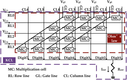
FIGURE 4. 4-bit crossbar multiplier structure. RL provides biasing for memristor, GL provides biasing for transistor, CL provides the current path for MC with different multiplier significance.
Since the multiplication is performed by fixed voltage values for 0 and 1 from the voltage operand, the output currents of cells in each column corresponding to logic 1 at these cells need to be set according to the column’s digit significance. Avoiding current-mirror amplifiers, this can be implemented by using x memristors in parallel with the appropriate x value. The relation between x and the digit significance N follows Eq. 1:
Let us use the 4-bit multiplier in Figure 4 as an example, assume cell transistors are ideal switches, VMH and VML as high voltage and low voltage operand inputs, and RMH and RML as high and low cell resistance (memristor resistance) operand inputs. In each cell, the possible output current states can be found in Figure 5 as I1, I2, I3, and I4. Since the logic 1 state is defined by VMH and RML, I4 is the output current representing logic 1, whilst the other three current states I1, I2 and I3 all represent logic 0 because at least one of their input operands encodes 0. Given the cell structure, none of I1, I2 and I3 can be true 0A. This is because RMH cannot be true infinity and to maintain the commutative property of multiplication, true 0 V should not be used in the voltage input operand either. Because of KCL, potentially a large number of relatively small I1, I2 and I3 values may be accumulated with the sum still required to represent a product value of 0. In other words, a single I4 needs to be greater in value than the sum of a large number of I1, I2 and I3 values to differentiate 0 and 1 at the final product.
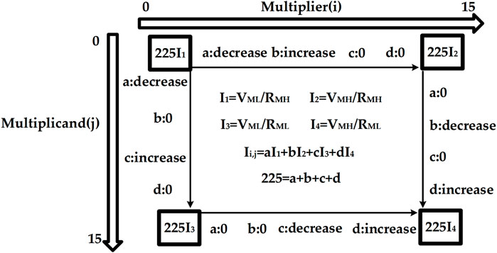
FIGURE 5. Mapping of all multiplication output current.
The final result Iout matrix shown in Figure 5 illustrates this issue in detail by enumerating all possible Iout values across all possible combinations of input operand values. This current map assumes that the operand encoded in voltage is called multiplier and the other operand encoded in memristor resistance is called multiplicand, without losing generality. Each operand is 4 bit wide and takes values from 0 to 15. When the multiplier increases from 0 to 15 we move from left to right along the i axis, 0 ≤ i ≤ 15, and when the multiplicand increases from 0 to 15 we move from top to bottom along the j axis, 0 ≤ j ≤ 15. At each position (i, j) in the matrix, Ii,j encodes the product of multiplying (multiplier = i) by (multiplicand = j). To simplify the presentation, we use four coefficients a, b, c and d to differentiate all the output currents and define Ii,j as Ii,j = aI1 + bI2 + cI3 + dI4. This means that moving down in the matrix, a decreases and c increases, with b and d held constant, and Move right in the matrix, b decreases and d increases, with a and c held constant. Because 15 × 15 = 225, a + b + c + d = 225. The four corner cases of the matrix are therefore Iout = 225I1, Iout = 225I2, Iout = 225I3, indicating final product values of 0 = 0 × 0 = 0 × 15 = 15 × 0, and Iout = 225I4 which indicates a final product value of 225 = 15 × 15.
For the 4-bit crossbar multiplier shown in Figure 5, the coefficients a, b, c and d are related to the operand values i and j according to Eqs 2–5
For a general N × N-bit multiplier, the equations above are replaced by Eqs 6–9, where 0 ≤ i ≤ (2N − 1) and 0 ≤ j ≤ (2N − 1).
From these, the output current for position (i, j) in the result current matrix can be found according to Eq. 10
Assuming a base voltage V0 ≠ 0 and base resistance R0 ≠ 0, we can relate the high and low memristor voltages and resistances to these vase values as in Eq. 11:
Then, the base current I0 = V0/R0 can be substituted into I1–I4, resulting in Eqs 12–15
Substituting Eq. 12–15 into Eq. 10 and simplifying the result, we obtain Eq. 16
It is evident that the multiplication is commutative iff
3.1.4 Precision analysis
This type of digital-in/analog-out multiplier does not represent Boolean 0 in the operands with true 0 values of physical parameters–the high resistance state (HRS) of a memristor cannot have a conductance of true 0 and the low resistance state (LHS) of a memristor cannot have a conductance of infinity. This means that Ii,j cannot be 0 amps even when it represents a Boolean value of 0. Consequently, when multiple Boolean 0’s are added together to produce an overall product P of 0, the actual value of Iout representing p = 0 is not 0 amps.
The maximal precision of such a multiplier is therefore limited by the ratio between RMH and RMH, which is technology-dependent. This is because the value of Iout that represents p = 0 must be lower than the value of Iout that represents p = 1. Conservatively, this is true if Iout representing p = 0 is lower than the current Ii,j representing a single bit value of 1. In other words, if the following inequality is true, the multiplier precision is not violated at a specific word length.
where PmaxN is the maximal value of the product for an N × N-bit multiplier. For instance, for a four-bit multiplier Pmax4 = 225 and for a five-bit multiplier Pmax5 = 969.
TiO2 memristors have a memristance state ratio between RMH and RML around 300 (Kvatinsky et al., 2014), which is marginally satisfactory for a four-bit multiplier, and Cu:ZnO memristors have a memristance state ratio around 1,000 (Suresh et al., 2019), which is marginally satisfactory for a five-bit multiplier. In this work, we select Cu:ZnO memristors for a four-bit implementation for a better accuracy margin and because the application itself does not demand high precision. With future memristor and other resistive non-volatile memory technologies, higher precision realizations may be possible.
Another important issue that may cause precision degredations in this type of multipliers is the variability of the crucial memristor characteristics RMH and RML. The effect of this variability will be investigated at the stage of final neural network application case studies (Section 6.3).
Comprehensive comparative studies of the crossbar part of the MAC including numerical correctness and non-functional metrics such as energy and speed can be found in (Yu et al., 2021).
3.2 Flash ADC
After the analog output Ii,j is generated, its value needs to be represented as an 4-bit (or N-bit for the general case) digital value either in memristor resistance or voltage encoding for the entire MAC unit to function in a multi-MAC NN using copies of the same MAC hardware. Since the memristor resistance values are written in by digital voltage signals, we do not lose generality if a 4-bit MAC outputs a 4-bit voltage encoded product (4 Boolean voltage signals).
We implement this functionality by using a flash ADC, designed from components adapted from (Bui et al., 2010; Vinayaka et al., 2019). The choice of using thermometer code as an intermediate step comes from the desire to make this MAC approximate in the sense of generating a 4-bit product from input operands which themselves are also in 4 bit width. This ADC consists of a single-action multiple-current comparator, buffer array and a ROM (read only memory) encoder. This section describes this part of the system in detail.
3.2.1 Thermometer code generating current comparator
In Figure 6A, the current comparator is represented. Given that the digital output is expected to be in 4 bits, the comparator is set to 16-value thermometer code output. The input current is mirrored by P-type current mirror which generates a row of pull up current sources, similarly, the reference current is mirrored by N-type current mirror which generates a row of pull down current sinks. By adjusting the size of M1 to MN, the reference current can be set to different levels. If a current source has a higher value than the corresponding current sink, the voltage at the junction point is pulled up to Vdd, otherwise, the junction point voltage is pulled down to ground. Therefore, the comparator will generate a thermometer code in the buffer array.
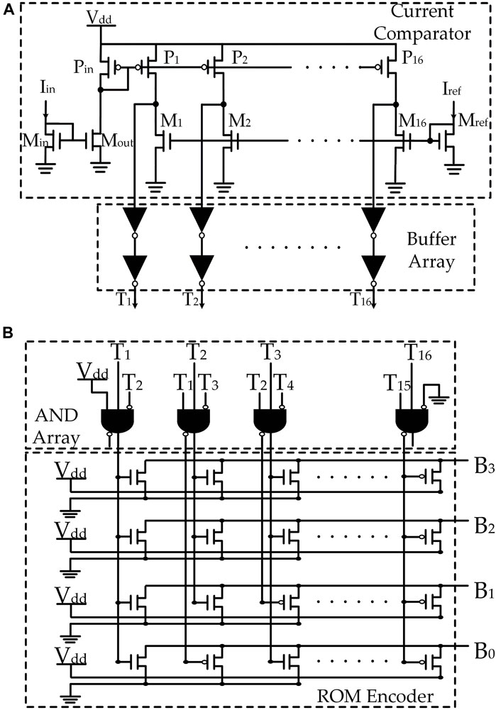
FIGURE 6. Structure of flash ADC. In (A), current comparator thermometer code generator (Vinayaka et al., 2019) is presented, in (B), ROM thermometer to binary encoder (Bui et al., 2010; Vinayaka et al., 2019) is presented.
In order to make this design work for our 4-bit crossbar mixed-signal multiplier, the transistor sizes need to be tuned to fit the multiplier current output characteristics. The details of MOS transistor size choices are listed in Table 1.
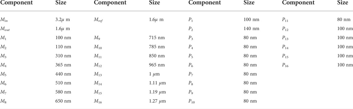
TABLE 1. Thermometer code generator transistor size.
3.2.2 Thermometer code to binary encoder
The thermometer code is an intermediary format which, after serving the purpose of fast comparison and product precision adjustment, has to be converted into voltage binary code for MAC output. The structure of the thermometer to binary encoder is presented in Figure 6B. As can be seen, this encoder consists of an AND gate array and a ROM encoder. For a 4-bit digital output, the 16-value thermometer code is first converted by the AND array to a 16-digit one hot code, which is then fed to the ROM encoder to generate a 4-bit binary output.
The complete MAC unit therefore accepts as inputs a multiplier in the form of 4-bit binary voltage signals and a multiplicand in the form of 4-bit binary memristor conductance values, and generates a product in the form of 4-bit binary voltage signals. This voltage-encoded 4-bit binary number can then be used directly as the multiplier for another MAC of the same configuration, or used to write the multiplicand for it. This means that the digital-to-digital MAC can be instantiated multiple times to form a NN or other machines that require a number of distinct MAC units of the same type working together.
4 Investigation of performance and functional correctness
This section describes results from investigating a number of implementations of our MAC unit. All parts of the system are realized in UMC 65 nm technology and studied in the Cadence Virtuoso environment through analog simulations.
4.1 Multiplication cell design
The structure of our multiplication cell is presented in Figure 3, the parallel connected memristors and transistors are marked with brown to indicate them operating under Ohm’s law. Similarly, cell output current path to column line is purple marked to indicate the KCL operation. Since the multiplication cell works as a conductive component on crossbar, both memristor and transistor contributes to the cell conductance. Therefore, it is important to ensure that the memristor dominates the cell conductance because we use the transistors as (ideal) switches. In other words, the high value of memductance should be much larger than the ON state transistor conductance, making the contribution to current by the transistor negligible. Meanwhile, the OFF state transistor conductance should be small enough to isolate a selected cell from the rest of the crossbar so that it can be in holding mode whilst other cells are written. With the memristor count for each cell determined by the digit significance, the transistor count and size need adjustments to balance that. Therefore, cells with fixed ratios of memristor count and transistor count are studied on our 4-bit crossbar multiplier.
In Figures 7A,B comparisons between crossbar with respective yTxM cell are shown. As can be seen, the 4-bit crossbar multiplier generates same levels of Iout with different count transistor-memristor cells, and the product values are symmetric between multiplicand and multiplier indicating commutative multiplication. However, the 1T2M cell stands out in the error rate comparison. The maximum error rate of 1T2M cell crossbar multiplier is 0.58% while for the 7T16M cell it is 0.72% and for the 15T32M cell it is 0.86%. Therefore, apart from the least significant bit using a 1T1M cell, all the multiplication cells in this 4-bit multiplier follow the memristor-transistor ratio of 1T2M, i.e., two memristors for each transistor in a cell.
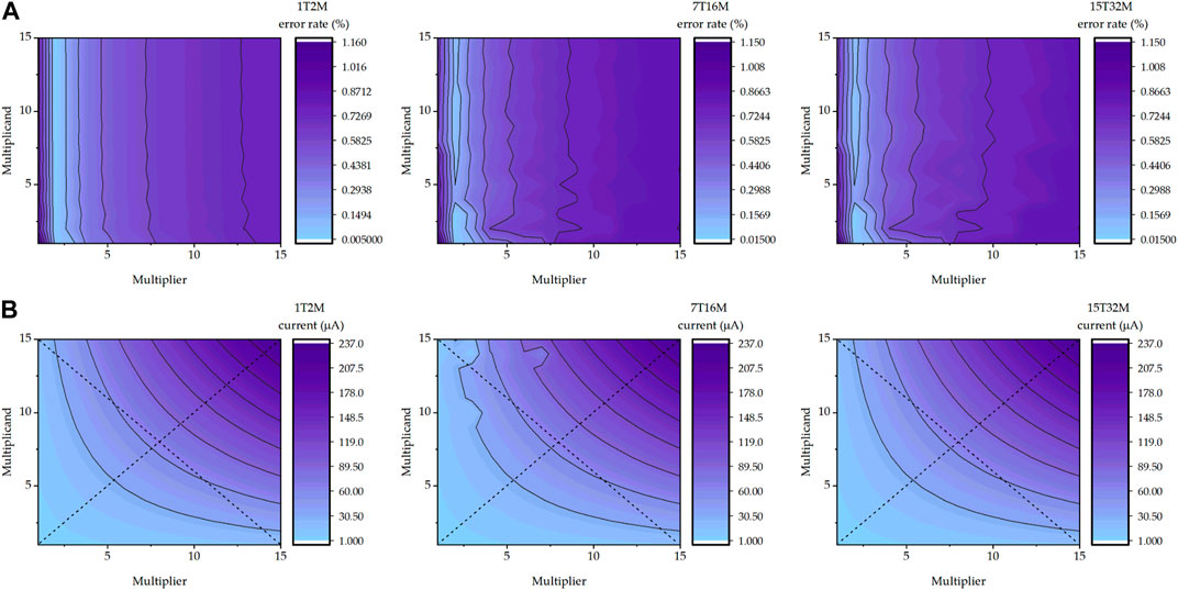
FIGURE 7. yTxM MC performance mapping. In (A), output current error rate in all 4 by 4 multiplications mapping is presented, in (B), output current in all 4 by 4 multiplications mapping is presented.
4.2 MAC unit design
The 4-bit crossbar multiplier shown in Figure 4 has two operations in each multiplication, writing (operand preparation) and reading (multiplying). When multiplication starts with a new multiplicand, all multiplication cells will be clear to LCS by each row line (RL), then the multiplicand is written by each gate line (GL) column. Finally, the reading (multiplier) voltages are applied on all RLs, meanwhile, all cell transistors are switched on. The multiplication result can be obtained from the ADC out terminal (See Figure 6B). When multiplying with an existing multiplicand, the writing step is omitted and the reading step directly starts. That is why this multiplier is well suited for asymmetrical multiplication applications such as multiplying variables to coefficient/reference values found in such applications as monitoring and control and certain operations of NNs where one of the operands (e.g., the multiplicand) does not change too often.
ADC transistor design parameters are presented in Table 1 and writing operation setting parameters are presented in Table 2. To reduce latency, the writing operations are parallelized on a per-row basis. To match the values of high and low memconductance, the reading (multiplier) voltage has values of 0.42 V as logic 0 and 0.7 V as logic 1. The total delay of each multiplication is 2 ns which is almost entirely ADC delay. Three multiplications 15 × 15, 15 × 0 and 9 × 6 are tested on the 4-bit multiplier, Figures 8A,B present the results.
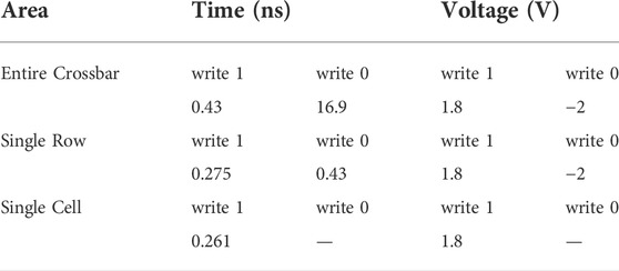
TABLE 2. Multiplier operation design details.
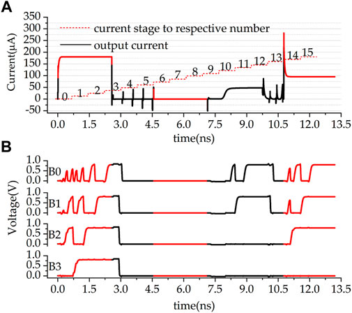
FIGURE 8. Three cases multiplication result. In (A), 3 multiplication output currents are presented, the red dash steps are the threshold for each digital output, in (B), respective digital output from B0 (LSB) to B3 (MSB) are presented. 0–2.97 ns is 15 × 15, 4.57 –7.13 ns is 0 × 0, and 10.77–13. 2ns is 9 × 6.
The red dash steps in Figure 8A are the thresholds for the current comparator, which translates currents to a thermometer code. For instance, Iout = 100 μA translates to the thermometer code value of 8, and 9 × 6 results in Iout ≈ 90 μA which translates to the thermometer code of 7. The output bit voltages are recorded in Figure 8B. Here B3 is the MSB and B0 the LSB. It can be seen that the ADC delay is data-dependent and the more bits are 1 the longer the delay. Since the less significant bits are settled after more significant bits and before then they may have swings. The output value of 1,111, corresponding to 15 × 15, takes just less than 2 ns to become stable, which is the worst-case delay of the MAC. In comparison, 0 × 0 incurs almost no delay.
Value-wise, 15 × 15 results in 1,111 (the largest number possible out of 4 bits). 15 × 0 results in 0000 and 9 × 6 results in 0111. These values work well for a 4-bit digital in and 4-bit digital out MAC unit.
5 Neural network case study
This section presents a case study to validate the proposed MAC unit. In this section, an MLA NN is created using copies of our MAC unit servicing as perceptrons. The machine learning problem solved with this NN is the classification of the MNIST dataset.
As our MAC unit supports only 4-bit inputs (integers), we need to apply a quantization technique to preserve the high accuracy while using such low-precision numbers. Two state of the art techniques exist for this, namely post-training quantization (PTQ) and quantization-aware training (QAT). Regarding PTQ, the weights will be quantized to the target bitwidth after the floating-point based training. This is a simple technique yet not suitable for
The most challenging issue in our NN training is that the output of our MAC unit contains variations due to its analog nature. To overcome this issue, we will use the same idea as QAT; the variations will be included in our training so that the NN can learn these variations and adjust its accuracy accordingly. In summary, this section contributes the QAT technique analysis to inject the MAC unit variations, the demonstration of NN training for MNIST classification and the accuracy comparison between the NN trained using our MAC unit and the basic 4-bit QAT NN. Note that, for the ease of computation analysis, our NN consists of fully-connected layers only. Extra software library development to include the proposed MAC unit in the convolution layers is considered as our future work.
5.1 QAT analysis
Fundamentally, fully-connected NN computation contains dot-product operations between weight matrices and input vectors. Eq. 18 means that the resulting matrix element r3 at row i and column k is obtained from the sum of products between the pairs of the weight matrix elements r1 at row i and the input vector elements r2 at column k. In general, these variables are presented precisely in floating-point format.
To compute the above equation using integer-arithmetic hardware, we need to quantize these real numbers. Following (Jacob et al., 2018), any real numbers can be quantized resulting positive quantized-values q in integers minus the zero-point Z and scaled by the scale factors S as shown in (Eq. 19). In addition, the range of q is between 0 and 2n−1, where n is the number of bits. Therefore, q in this work is in the [0, 15] range (4-bit unsigned integer).
Replacing the weights r1 and inputs r2 in (Eq. 18) by Eq. 19 yields Eq. 20 which can be re-written as Eq. 21:
In Eq. 21 there is no dot-product operation on floating-point numbers; it happens only in the term
Another issue is that our MAC unit is centered around an analog product. It therefore contains a non-ideal effect where its multiplication results deviates from the expected values as shown in Table 3, which is obtained from analog simulations of a single MAC unit. Note that the errors in this input-output correspondence error map shows that the actual full-MAC implementation has more errors than the crossbar itself given in Section 3.1.4. This is because the DAC part introduces more errors. However, the maximal error value of −5 shows that the MAC is still a four-bit unit with a higher resolution than a three-bit device (the maximal possible output value of this MAC is 15). In Eq. 22, we add
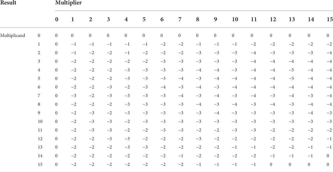
TABLE 3. Multiplication errors of the proposed MAC unit.
From Eq. 22, we can separate the loss term from the main bracket by multiplying the scale factors S1 and S2 as expressed in (Eq. 23). It can be seen that the large term remains the same as (Eq. 21). Therefore, we can conclude that the variation in our MAC unit can be simulated by subtracting the product of both scale factors and the sum of the MAC unit’s errors from the basic dot-product’s result. Eq. 24 will be added to our training graph as explained in the next section.
6 Results and discussions
6.1 MAC units
Our study is mainly based on worst-case delay assumptions. The worst-case multiplication cycle includes 4 row writing 0 (reset) operations with 1.72 ns delay, 4 row writing 1 (set) operations with 1.1 ns delay, and one entire crossbar reading (multiply + ADC) operation with 2 ns delay, which represents an order of magnitude speedup over existing memristor-based multipliers reported in (Guckert and Swartzlander, 2017). The average power is 290 μW, also lower than the competition. The average energy consumption per multiplication cycle of the 4-bit 1T2M crossbar multiplier is 1.39 pJ over a 4.82 ns period.
The writing delay and energy costs are reduced from (Guckert and Swartzlander, 2017) because in the latter both operands are represented by memristor conductance values with the high memristor writing costs incurred twice. The structures of the multipliers featured in (Guckert and Swartzlander, 2017) also incur more delays compared with our crossbar mixed-signal approach because the latter takes advantage of resistive Ohm’s Law and KCL. In addition, these are worst-case comparisons where both operands need to be written completely with the greatest writing delay considered. For the case where only one of the operands needs updating (and it happens to be the one with the more frequent updating requirement) our MAC will fare much better as there is no memristor writing. For applications where the writing frequency requirements for the two operands are asymmetric, our solution would show much greater improvements.
The energy per multiplication cycle worst case happens with 15 × 15 because of its longest delay and highest Iout value (187.3 μA) among all multiplication cases. This worst-case cycle has an energy consumption of 3.91 pJ. The best case happens with 0 × 0 which requires only 0.00524 pJ of energy to complete, primarily because parameter setting, crossbar and ADC all take negligible time and in addition the currents and voltages also take low values.
The energy consumption of our MAC unit is compared with state-of-the-art memristor multipliers in Table 4. Generally, the proposed work saves 83.7% and 74.1% energy per multiplication cycle than the MAD shift-and-add multiplier and optimized MAD shift-and-add multiplier in their respective worst cases. In the best case, the energy saving can reach almost 99% comparative energy savings. Even the average energy consumption of the proposed MAC unit, at 1.39 pJ, is significantly lower than the best case figures achieved by the competition.
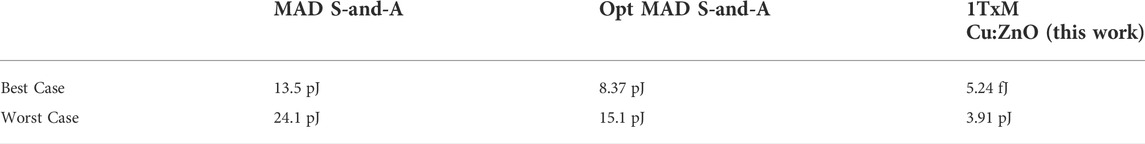
TABLE 4. Energy consumption per multiplication comparison with memristor-based MAD shift-and-add multiplier and optimized MAD shift-and-add multiplier (Guckert and Swartzlander, 2017).
These very low energy consumption figures are based on the assumption that the crossbar part of the MAC is shut down after a cycle of operation ends before the next cycle starts. This crossbar structure should not be used to hold a constant output as that entails a continuous Iout needing to be maintained. In practice this can be solved by holding the output of the MAC in a register and powering down the crossbar when not needed. With one of the operands in non-volatile memory and the other the responsibility of the supplier of the voltage input, this regime does not introduce operational difficulties.
6.2 NN training and results
To demonstrate the application of the proposed MAC unit in our NN training, we constructed a three fully-connected layers perceptron for MNIST classification as illustrated in Figure 9A. MNIST is chosen because it is commonly used for proving and benchmarking the NN hardware design concepts in the literature Mileiko et al. (2020); Amirsoleimani et al. (2020); Wang et al. (2020); Krestinskaya et al. (2020), especially for low-power edge applications and suitable as a proof of concept in this paper. We explore our 4-bit MAC with MNIST to demonstrate its validity in NN applications. This is the same approach taken by the authors of (Trusov et al., 2021), who targeted a mobile-relevant dataset with their 4-bit low-power NN. It is not our intention to confirm the NN application scalability of 4-bit MACs, given that the case has been proven in the state of the art (Sun et al., 2020).
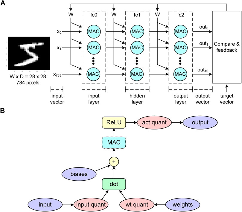
FIGURE 9. (A) Neural network structure to demonstrate MNIST classification using the proposed MAC unit. It consists of three fully-connected layers, each of which (input/hidden/output) contains 800/500/10 neurons. The traditional MAC unit will be replaced by the proposed one. (B) The training graph of the neural network in (A). We added the MAC block (highlighted in blue) where the output of the dot-product will be subtracted by the non-ideal effect of our MAC unit following Eq. 24 and the multiplication errors in Table 3. This allows the neural network to learn the loss regarding the proposed MAC unit.
In addition, this demonstration aims to show the NN-type applications’ ability to absorb the output variations of our MAC unit. In other words, we need to validate the MAC design through demonstrating its usefulness for NN applications even under worst-case MAC variation scenarios including worst-case memristor RML and RMH value combinations.
The numbers of neurons in the input/hidden/output layers are 800/500/10. The forward-pass calculation of each layer follows the graph in Figure 9B. Regarding the QAT concept, the inputs and weights of each layer are quantized and de-quantized based on Eq. 19 to simulate the quantization error. Note that this procedure is known as fake quantization in the literature (Chahal, 2019). In addition, the resolution of q is set to 4-bit, which is consistent with the input resolution of our MAC unit.
Then, the dot-product of the inputs and weights are preformed and the biases are added. Next, we insert a MAC block to subtract the dot-product results by our MAC’s output variations as explained in Section 5.1. After this step, the MAC block’s results pass the ReLU activation function and another fake quantization of the activation is executed. Finally, the layer’s output will be the input of the next layer.
Three NN configurations as listed in Table 5 have been implemented using the PyTorch library (Paszke et al., 2019). The first one, which is our baseline, is the 4-bit QAT NN obtained from (Chahal, 2019) without the convolution layers. The backward pass is implemented using stochastic gradient descent while the straight through estimator is applied for the fake quantization blocks. The related parameters are as follows: batch size = 64, learning rate = 0.01 and momentum = 0.5. To inspect the effect of the MAC’s output variations, the second NN is trained using the above procedure while the variations are injected only in the testing phase. Lastly, the variations are included in both training and testing phases to evaluate the accuracy improvement.
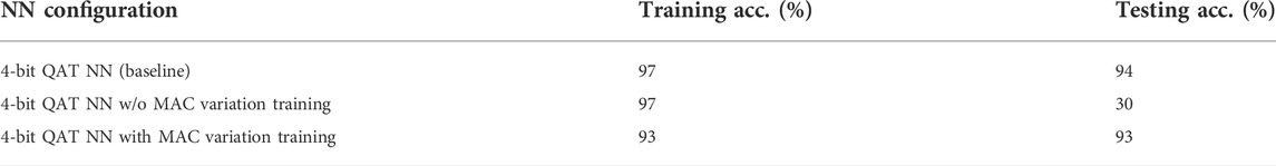
TABLE 5. MNIST classification accuracy comparison.
Table 5 shows our baseline yields the testing accuracy of 94%, which is only 4% accuracy drop from the convolutional NN implementation by (Chahal, 2019). This means the implementation with pure fully-connected layer is acceptable for MNIST classification. Without simulating the impact of our MAC unit in the NN training, however, the accuracy substantially drops to 30%. This confirms the MAC unit simulation is highly required in the training phase. Finally, the accuracy is back up to 93% when training the NN with the MAC’s output variations. This implies the proposed MAC unit is applicable for NN applications and that variation injection is required during the NN training to maintain the accuracy.
6.3 Effects of technology parametric variations
However, device parametric variation in multiplication cell may lead to additional and substantial analog output error. Devices may have different properties or technology parametric variations. For our MAC, we consider faster/slower operating speeds of transistors and higher/lower RMH and RML values of memristors. Therefore, the multiple-component cell design in this work risks large accuracy drops resulting from such variations. Both the transistor variation and memristor variation have been investigated to show the relation between variation and NN accuracy of MNIST classification.
The variability transistor models are investigated first. The fabricated transistor’s performance can be modeled as Fast-Fast (FF), Typical-Typical (TT), and Slow-Slow (SS) corners. Analog simulations of the MAC corresponding with these corners are used to generate modified MAC input to output error maps in the same style as Table 3. Then respective NN simulation using the method given in Section 6.2 generates the accuracy results reported in Table 6.
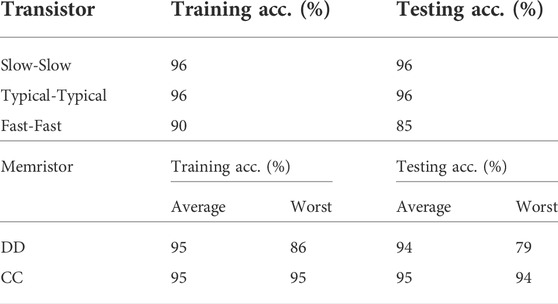
TABLE 6. QAT NN with MAC component variation training.
Then we investigate the effects of memristor resistance variability. As shown in (Siddik et al., 2020), for the technology of our choice (Cu:ZnO), the device-to-device (DD) variability is 59% for the high resistance state (HRS) and 36% for the low resistance state (LRS), while the cycle-to-cycle (CC) variability is 89% for the HRS and 51% LRS for the LRS. Note that although the CC variability is especially large, it is not possible for RML to become higher than RMH given that the baseline ratio between these two parameters is 1,000 for the Cu:ZnO technology.
Similar to the case of transistor variation investigations, our simulation investigations include analog simulations of one MAC unit with all possible corner cases of expected variability in the memristors. The result of these simulations are put into digital models in the form of input value to output value correspondence error maps in the form of Table 3. These corner case models are then used in NN training exercises on the MNIST dataset, using exactly the same method described in Section 6.2. The accuracy results are reported in Table 6.
In presenting these results we focus on investigating how the worst-case scenarios of memristor variability may affect the NN application and compare with the average case. The worst case happens when RMH takes the lowest possible value coinciding with RML taking the highest possible value. This maximally reduces the margin between these two values and hence reduce the precision of the multiplier part of the MAC, as discussed in Section 3.1.4.
The reported average case results are the average values obtained from all different corner cases and do not correspond with any one particular set of parameter value. It is noteworthy that some of the accuracy numbers reported in Table 6 are actually better than those reported in the last row of Table 5. This is because in many cases, the technology parametric variation corner cases have smaller errors in their input-output relation error maps than the non-variation case of Table 6. This is a result of effective cancellations between the two kinds of errors. The true global worst case results, however, do happen with worst-case memristor parametric variation combinations.
As can be seen from the results, in all experiments both training and testing always successfully complete, but in the highlighted cases the accuracy does not achieve better than 90%. However, even the global worst case of 79% accuracy should be tolerable for low-power edge AI applications. It is also noteworthy that NN operations seem to be especially resistant to the CC type of parametric variability. This is likely because NN operations usually include a substantial number of cycles during which CC variability in the MACs is moderated by a kind of low-pass filtering process.
7 Conclusion
In this paper, a MAC unit based on a crossbar multiplier is presented. By using memristor-transistor single-bit multiplication cells with mixed-signal design, this crossbar multiplier removes the need for carry propagation. Multiplying by passive current generation across resistive elements only, the multiplication step itself can be regarded as instantaneous according to Ohm’s law and KCL. By using a mixed-mode, flash ADC conversion step, latency is kept under control for the ultimate digital-in/digital-out unit through single-action thermometer code generation. This means that the worst case delay depends only on writing memristor values and converting thermometer code to binary code. This latency management means that the MAC unit has a relatively low worst-case latency. At the same time, the energy efficiency is also improved over conventional digital multipliers using memristors by eliminating the need for costly carry-to-the-left operations.
The proposed MAC unit also has the same precision for both input and output, which means that it can be used to compose multi-MAC structures such as NNs without worrying about bit-conversion when fitting outputs of one layer to the inputs of another layer. The approximation happens in the thermometer code generation step where it leads to circuit size and complexity reductions in subsequent circuitry without sacrificing precision unnecessarily.
To validate this MAC unit, it is used as the basic perceptron in the creation of an NN of multiple neurons and layers, and the resulting NN is used to classify the MNIST dataset. The low precision and multiplication errors attributed to the analog product from the crossbar multiplier are shown to be compensatable through an extended use of QAT. With such compensation techniques, our case study NN achieves comparable learning accuracy to the same NN based on fully-digital QAT MAC units of the same bit width. In doing this, we additionally demonstrate the potential for extending QAT to compensate for any characterizable imprecision beyond quantization effects in the perceptron unit. The effects of parametric variability for both transistors and memristors are also investigated demonstrating the usability of this type of MAC units.
Data availability statement
The raw data supporting the conclusions of this article will be made available by the authors, without undue reservation.
Ethics statement
Written informed consent was obtained from the individual(s) for the publication of any potentially identifiable images or data included in this article.
Author contributions
SY and TB contributed to conception and design of the study, SY organized the database. SY and TB performed the statistical analysis. SY wrote the first draft of the manuscript. TB and FX wrote sections of the manuscript. RS and AY designed the original hypothesis and contributed to optimizing the circuit designs. They also reviewed and revised the manuscript. All authors contributed to manuscript revision, read, and approved the submitted version.
Funding
The authors gratefully acknowledge funding support from EPSRC IAA project Whisperable AI Power Management (ref: NU-007755, Newcastle University, United Kingdom) and Northern Accelerator grant on Low-Power AI Circuits (NU-009397, Newcastle University).
Conflict of interest
The authors declare that the research was conducted in the absence of any commercial or financial relationships that could be construed as a potential conflict of interest.
Publisher’s note
All claims expressed in this article are solely those of the authors and do not necessarily represent those of their affiliated organizations, or those of the publisher, the editors and the reviewers. Any product that may be evaluated in this article, or claim that may be made by its manufacturer, is not guaranteed or endorsed by the publisher.
References
Amirsoleimani, A., Alibart, F., Yon, V., Xu, J., Pazhouhandeh, M. R., Ecoffey, S., et al. (2020). In-memory vector-matrix multiplication in monolithic complementary metal–oxide–semiconductor-memristor integrated circuits: Design choices, challenges, and perspectives. Adv. Intell. Syst. 2, 2000115.
Berdan, R., Khiat, A., Papavassiliou, C., and Prodromakis, T. (2014). “Qualitative SPICE modeling accounting for volatile dynamics of TiO2 memristors,” in 2014 IEEE Int. Sym. Circuits & Systems (ISCAS), 2033–2036. doi:10.1109/ISCAS.2014.6865564
Borghetti, J., Snider, G. S., Kuekes, P. J., Yang, J. J., Stewart, D. R., and Williams, R. S. (2010). ‘memristive’ switches enable ‘stateful’ logic operations via material implication. Nature 464, 873–876. doi:10.1038/nature08940
Bui, V. H., Beak, S., Choi, S., Seon, J., and Jeong, T. T. (2010). “Thermometer-to-binary encoder with bubble error correction (BEC) circuit for flash analog-to-digital converter (FADC),” in International Conference on Communications and Electronics 2010 (Nha Trang, Vietnam: IEEE), 102–106.
Chen, W. H., Dou, C., Li, K. X., Lin, W. Y., Li, P. Y., Huang, J. H., et al. (2019). Cmos-integrated memristive non-volatile computing-in-memory for ai edge processors. Nat. Electron. 2, 420–428. doi:10.1038/s41928-019-0288-0
Chua, L. (1971). Memristor-the missing circuit element. IEEE Trans. Circuit Theory 18, 507–519. doi:10.1109/tct.1971.1083337
Cilardo, A., De Caro, D., Petra, N., Caserta, F., Mazzocca, N., Napoli, E., et al. (2014). High speed speculative multipliers based on speculative carry-save tree. IEEE Trans. Circuits Syst. I. 61, 3426–3435. doi:10.1109/tcsi.2014.2337231
Constantoudis, V., Papavieros, G., Karakolis, P., Khiat, A., Prodromakis, T., and Dimitrakis, P. (2019). Impact of line edge roughness on ReRAM uniformity and scaling. Materials 12, 3972. doi:10.3390/ma12233972
[Dataset] Chahal, K. (2019). Aggressive quantization: How to run MNIST on a 4 bit neural net using pytorch.
Fujiki, D., Wang, X., Subramaniyan, A., and Das, R. (2021). In-/near-memory computing. Synthesis Lect. Comput. Archit. 16, 1–140. doi:10.1007/978-3-031-01772-8
Guckert, L., and Swartzlander, E. E. (2017). Optimized memristor-based multipliers. IEEE Trans. Circuits Syst. I. 64, 373–385. doi:10.1109/tcsi.2016.2606433
Gupta, I., Serb, A., Khiat, A., Zeitler, R., Vassanelli, S., and Prodromakis, T. (2016). Real-time encoding and compression of neuronal spikes by metal-oxide memristors. Nat. Commun. 7, 12805–12809. doi:10.1038/ncomms12805
Ho, Y., Huang, G. M., and Li, P. (2009). “Nonvolatile memristor memory: Device characteristics and design implications,” in 2009 Int. Conf. Computer-Aided Design (ICCAD’09), San Jose, CA, USA, November 2-5, 2009, 485–490.
Hung, J.-M., Jhang, C.-J., Wu, P.-C., Chiu, Y.-C., and Chang, M.-F. (2021). Challenges and trends of nonvolatile in-memory-computation circuits for ai edge devices. IEEE Open J. Solid. State. Circuits Soc. 1, 171–183. doi:10.1109/ojsscs.2021.3123287
Jacob, B., Kligys, S., Chen, B., Zhu, M., Tang, M., Howard, A., et al. (2018). “Quantization and training of neural networks for efficient integer-arithmetic-only inference,” in IEEE/CVF Conf. Computer Vision and Pattern Recognition, 2704–2713. doi:10.1109/CVPR.2018.00286
Khan, R., Ilyas, N., Shamim, M. Z. M., Ilyas Khan, M., Sohail, M., Rahman, N., et al. (2021). Oxide-based resistive switching-based devices: Fabrication, influence parameters and applications. J. Mater. Chem. C 9, 15755–15788. doi:10.1039/D1TC03420K
Krestinskaya, O., Choubey, B., and James, A. (2020). Memristive GAN in analog. Sci. Rep. 10, 5838. doi:10.1038/s41598-020-62676-7
Kvatinsky, S., Belousov, D., Liman, S., Satat, G., Wald, N., Friedman, E. G., et al. (2014). MAGIC—memristor-aided logic. IEEE Trans. Circuits Syst. Ii. 61, 895–899. doi:10.1109/TCSII.2014.2357292
Kvatinsky, S., Friedman, E. G., Kolodny, A., and Weiser, U. C. (2013). TEAM: ThrEshold adaptive memristor model. IEEE Trans. Circuits Syst. I. 60, 211–221. doi:10.1109/TCSI.2012.2215714
Kvatinsky, S., Ramadan, M., Friedman, E. G., and Kolodny, A. (2015). Vteam: A general model for voltage-controlled memristors. IEEE Trans. Circuits Syst. Ii. 62, 786–790. doi:10.1109/TCSII.2015.2433536
Lehtonen, E., and Laiho, M. (2010). “CNN using memristors for neighborhood connections,” in 2010 12th Int. Workshop on Cellular Nanoscale Networks and their Applications (CNNA 2010), 1–4. doi:10.1109/CNNA.2010.5430304
Li, C., Hu, M., Li, Y., Jiang, H., Ge, N., Montgomery, E., et al. (2018). Analogue signal and image processing with large memristor crossbars. Nat. Electron. 1, 52–59. doi:10.1038/s41928-017-0002-z
Mileiko, S., Bunnam, T., Xia, F., Shafik, R., Yakovlev, A., and Das, S. (2020). Neural network design for energy-autonomous artificial intelligence applications using temporal encoding. Phil. Trans. R. Soc. A 378, 20190166. doi:10.1098/rsta.2019.0166
Nagel, M., Fournarakis, M., Amjad, R. A., Bondarenko, Y., van Baalen, M., and Blankevoort, T. (2021). A white paper on neural network quantization. arXiv e-prints.
Park, E., Kim, D., and Yoo, S. (2018). “Energy-efficient neural network accelerator based on outlier-aware low-precision computation,” in 2018 ACM/IEEE 45th Annual International Symposium on Computer Architecture (ISCA) (Los Angeles, CA, USA: IEEE), 688–698.
Paszke, A., Gross, S., Massa, F., Lerer, A., Bradbury, J., Chanan, G., et al. (2019). “Pytorch: An imperative style, high-performance deep learning library,” in Advances in neural information processing systems 32. Editors H. Wallach, H. Larochelle, A. Beygelzimer, F. d'Alché-Buc, E. Fox, and R. Garnett (New York, NY, USA: Curran Associates, Inc.), 8024–8035.
Qiqieh, I., Shafik, R., Tarawneh, G., Sokolov, D., Das, S., and Yakovlev, A. (2018). Significance-driven logic compression for energy-efficient multiplier design. IEEE J. Emerg. Sel. Top. Circuits Syst. 8, 417–430. doi:10.1109/JETCAS.2018.2846410
Radwan, A. G., Zidan, M. A., and Salama, K. N. (2012). “HP Memristor mathematical model for periodic signals and DC,” in IEEE Int. Midwest Sym. on Circuits & Systems (Seattle, WA, USA: IEEE), 861–864.
Shafik, R. A., Yang, S., Das, A., Maeda-Nunez, L. A., Merrett, G. V., and Al-Hashimi, B. M. (2016). Learning transfer-based adaptive energy minimization in embedded systems. IEEE Trans. Comput. -Aided. Des. Integr. Circuits Syst. 35, 877–890. doi:10.1109/tcad.2015.2481867
Shafik, R., Yakovlev, A., and Das, S. (2018). Real-power computing. IEEE Trans. Comput. 67, 1445–1461. doi:10.1109/TC.2018.2822697
Siddik, A., Haldar, P. K., Garu, P., Bhattacharjee, S., Das, U., Barman, A., et al. (2020). Enhancement of data storage capability in a bilayer oxide-based memristor for wearable electronic applications. J. Phys. D. Appl. Phys. 53, 295103. doi:10.1088/1361-6463/ab81d3
Singh, S., Prasad, P. W. C., Alsadoon, A., Beg, A., Pham, L., and Elchouemi, A. (2016). “Survey on memrister models,” in 2016 Int. Conf. Electronics, Information, and Communications (ICEIC), 1–7. doi:10.1109/ELINFOCOM.2016.7563017
Strukov, D. B., Snider, G. S., Stewart, D. R., and Williams, R. S. (2008). The missing memristor found. Nature 453, 80–83. doi:10.1038/nature06932
Sun, X., Wang, N., Chen, C. Y., Ni, J., Agrawal, A., Cui, X., et al. (2020). “Ultra-low precision 4-bit training of deep neural networks,” in NeurIPS.
Suresh, B., Boppidi, P. K. R., Rao, B. P., Banerjee, S., and Kundu, S. (2019). Realizing spike-timing dependent plasticity learning rule in pt/cu: Zno/nb: Sto memristors for implementing single spike based denoising autoencoder. J. Micromech. Microeng. 29, 085006. doi:10.1088/1361-6439/ab235f
Trusov, A., Limonova, E., Slugin, D., Nikolaev, D., and Arlazarov, V. V. (2021). “Fast implementation of 4-bit convolutional neural networks for mobile devices,” in 2020 25th International Conference on Pattern Recognition (ICPR), 9897–9903. doi:10.1109/ICPR48806.2021.9412841
Vinayaka, V., Namboodiri, S. P., Abdalla, S., Kerstetter, B., Mata-carlos, F., Senda, D., et al. (2019). “Monolithic 8x8 sipm with 4-bit current-mode flash adc with tunable dynamic range,” in Proceedings of the 2019 on Great Lakes Symposium on VLSI, 57–62.
Wang, R., Yang, J. Q., Mao, J. Y., Wang, Z. P., Wu, S., Zhou, M., et al. (2020). Recent advances of volatile memristors: Devices, mechanisms, and applications. Adv. Intell. Syst. 2, 2000055. doi:10.1002/aisy.202000055
Yakovlev, A. (2015). “Enabling survival instincts in electronic systems: An energy perspective,” in Transforming reconfigurable systems (London, UK: Imperial College Press), 237–263. doi:10.1142/9781783266975_0013
Yu, S., Shafik, R., Bunnam, T., Chen, K., and Yakovlev, A. (2021). “Optimized multi-memristor model based low energy and resilient current-mode multiplier design,” in 2021 Design, Automation Test in Europe Conference Exhibition (DATE), 1230–1233. doi:10.23919/DATE51398.2021.9473926
Yu, S., Shafik, R., Bunnam, T., Chen, K., and Yakovlev, A. (2020a). “Self-amplifying current-mode multiplier design using a multi-memristor crossbar cell structure,” in 2020 27th IEEE Int. Conf. Electronics, Circuits and Systems (ICECS), 1–4. doi:10.1109/ICECS49266.2020.9294797
Yu, S., Soltan, A., Shafik, R., Bunnam, T., Xia, F., Balsamo, D., et al. (2020b). “Current-mode carry-free multiplier design using a memristor-transistor crossbar architecture,” in 2020 Design, Automation Test in Europe Conf. Exhibition (DATE), 638–641. doi:10.23919/DATE48585.2020.9116417
Yuan, F. (2006). Low-voltage CMOS current-mode circuits: Topology and characteristics. IEE Proc. Circuits Devices Syst. 153, 219–230. doi:10.1049/ip-cds:20045058
Keywords: in memory computing, energy-efficient, neural network, multiply-accumulate (MAC) unit, quantization-aware training (QAT), mixed-signal (MS)
Citation: Yu S, Bunnam T, Triamlumlerd S, Pracha M, Xia F, Shafik R and Yakovlev A (2022) Energy-efficient neural network design using memristive MAC unit. Front. Electron. 3:877629. doi: 10.3389/felec.2022.877629
Received: 16 February 2022; Accepted: 31 August 2022;
Published: 26 September 2022.
Edited by:
Yu Cao, Arizona State University, United StatesReviewed by:
Mohammed Fouda, University of California, Irvine, United StatesXueqing Li, Tsinghua University, China
Copyright © 2022 Yu, Bunnam, Triamlumlerd, Pracha, Xia, Shafik and Yakovlev. This is an open-access article distributed under the terms of the Creative Commons Attribution License (CC BY). The use, distribution or reproduction in other forums is permitted, provided the original author(s) and the copyright owner(s) are credited and that the original publication in this journal is cited, in accordance with accepted academic practice. No use, distribution or reproduction is permitted which does not comply with these terms.
*Correspondence: Shengqi Yu, cy55dTEwQG5ld2Nhc3RsZS5hYy51aw==; Rishad Shafik, cmlzaGFkLnNoYWZpa0BuZXdjYXN0bGUuYWMudWs=; Alex Yakovlev, YWxleC55YWtvdmxldkBuZXdjYXN0bGUuYWMudWs=