 Lucia Margheritini1*
 Per Møldrup1Rasmus Lund Jensen1Kirstine Meyer Frandsen1Yovko Ivanov Antonov1Ken Kawamoto2Lis Wollesen de Jonge3Raffaele Vaccarella4Trine Larsen Bjørgård5
 Morten Enggrob Simonsen5
- 1Department of the Built Environment, Aalborg University, Aalborg, Denmark
- 2Department of Civil and Environmental Engineering, Saitama University, Saitama, Japan
- 3Department of Agroecology, Aarhus University - Foulum, Aarhus, Denmark
- 4Marine Biology Laboratory of Province, Bari, Italy
- 5Department of Chemistry and Bioscience, Aalborg University Esbjerg, Esbjerg, Denmark
Low-Voltage Mineral Deposition technology (LVMD), widely known as Biorock, has previously been suggested as support for coral reef restoration, as hypothesized high porosity, wide pore-size distribution and connectivity, and good strength properties may facilitate biological functions (for example larvae settlement) and durability. In this technology, very low voltage induces an electrical current that initiates precipitation and accretion of hard minerals (aragonite and calcite) on a metal in seawater. This technology has been discussed mainly for its biological value, while this paper wants to highlight also its engineering value as artificial reef material. Indeed, some of the properties that makes it valuable in one domain are also supporting its use in the other. Because the metal on which the precipitation takes place can be of any shape and size, so can the artificial reef and its mechanical strength characteristics are above the ones of corals and similar to concrete, indicating adequate durability. Coral and boulder reefs suffering from degradation have severe implications on biodiversity, protection from flooding, and cultural value and therefore understanding how to persevere and re-establish these ecosystems is central for sustainable intervention in the marine environment. By comparing chemical-physical characteristics of Coral Porites Exoskeleton (CPE), one typical reef building coral type, LVMD and High-Voltage Mineral Deposition (HVMD), we show that they possess highly similar properties including chemical composition, density, total porosity, pore-size distribution, physical and chemical heterogeneity, total and external surface areas, and comparable mechanical strength.
Introduction
Reefs can be either biogenic concretions (such as coral reefs) or of geogenic origin (rocky, boulder reefs). They are hard compact substrata on solid and soft bottoms, which rise from the sea floor nearshore and in the littoral zone (European Commission, 2007). In both cases, they are important ecosystems, functioning as nurseries, hosting high biodiversity and biomasses. They also provide an important ecosystem benefit by protecting coasts from erosion and flooding, by trapping sediments and absorbing up to 97% of wave energy (Ferrario et al., 2014) as low-crested breakwaters (Gallop et al., 2014). Attributes that allow reefs to perform their coastal protection and ecological services include: surface roughness, depth of the crest, slope and surface of the assembly contribute directly to wave dissipation. Additionally, coral reefs are like factories of calcium carbonate and their natural degradation in time provides a continuous supply of sediments to the beach (Sheppard et al., 2005). Rates of carbonate production from coral reefs are some of the highest in the world (1,000–4,000 g calcium carbonate m2/y; Mallela and Perry, 2007). The balance between carbonate production and erosion is symptomatic of the health of the system. Erosion causes a loss of the three-dimensional structure and a flattening of the reef surface; it is generated by bio-erosion by fish and bio-eroding organisms, but physical and chemical erosion may be dominant (Perry et al., 2013). The necessary strength of the reefs to survive wave forces and mechanical erosion is to be found in the structure (and porosity) of the material at micro- and macro-scales. Finally, the abundance of microhabitats provides shelter and sustains a complex ecosystem, where many different organisms perform important roles improving water quality and regulating nutrients supply, and where symbiotic and mutually beneficial relations among species thrive. Additionally, attachment of spore and/or coral larvae to substrate is effected by the pore size in coral reefs (Whalan et al., 2015).
Both coral and boulder reefs suffer from degradation with clear negative implications on biodiversity, fisheries, protection from flooding and coastal storms, cultural and aesthetic value. It is estimated that more than 50% of the coral reef are in medium and high risk of degradation (Burke et al., 2011) due to unsustainable coastal development, contamination, nutrient enrichment, overfishing and ocean warming (inducing bleaching and mortality). Particularly, under future climate-related effects (ocean warming and acidification, sea level rise, increase of extreme events), even in view of positive coral adaptation to thermal stress, between one- to two-thirds of the world’s coral reefs are projected to be subject to long-term degradation (Frieler et al., 2013; Lenton et al., 2019). Even if present-day corals have had residual capacity to acclimate and/or adapt, half of the coral reefs may avoid high-frequency bleaching from now to 2100 (Logan et al., 2014). Regrettably, there is no unequivocal evidence of corals adapting rapidly enough (Hoegh-Guldberg, 2012). Boulder reefs do not necessarily have a better fate: they have been used as a source of construction materials. An example could be the events in Denmark prior to the amendment to the Danish Raw Materials Act on 1 January 2010 that banned the removal of stones and boulders from sea beds. It is conservatively estimated that 40 km2 of exposed stone surface has been removed from stone reefs in coastal Danish waters (Støttrup et al., 2014). The extent of loss of the services provided by reefs largely depend on how well threats are reduced and managed. Within protection and restoration practices, one clear separation exists between engineered structures for coastal protection and artificial reefs. Coastal protection structures, such as breakwaters and groins, are designed using well-established engineering tools and models (e.g., USACE 2002; Sabatier, 2002) with the purpose of meeting the needs of the population living on the coast with limited or no regards to natural benefits. Artificial reefs, on the other hands, are structures placed on the seabed to mimic functions of natural reefs, enhancing the population of living marine resources, including protection and regeneration of habitats; guidelines have been derived from general regional regulations addressing the compatibility of the used materials with the marine environment (Fabi et al., 2015). Particularly, to avoid degradation and pollution from unsuitable materials the London Convention and Protocol/UNEP, 2009 indicates that the materials should (1) be inert, (2) take into consideration resistance to the chemical and physical forces, (3) have a lifetime of minimum 30 years, and (4) be suitable for colonization by benthic communities. Both ecological and engineering schools of thought could be merged into integrated designs for a more effective and holistic approach that could provide viable long-term strategies for coastal management. Degraded reefs can be structurally and functionally restored using biological, physical and artificial techniques, incorporating a nature-based principle into engineered breakwaters (World Bank Group, 2016). Therefore, the suitability of the materials needs to be addressed considering requirements from both expertise.
In this contest, the low-voltage mineral deposition technology (LVMD, in some biological applications known as Biorock), uses direct current to grow underwater limestone structures on a metal frame of any shape and size in the sea. These structures are self-repairing and can function as breakwaters to protect the coast if the design is optimized to this purpose. LVMD can be speeded up by increasing the voltage (HVMD) and allowing the precipitation also of Magnesium Hydroxide (Brucite), instead of calcium carbonate (Araginite). In addition, the process has shown stimulatory effects on different forms of marine life (Vaccarella and Goreau, 2012). Particularly, reef-building corals, soft corals, oysters and salt marsh grass have shown growth rates 3.17 times faster than controls, which could be an advance when faster restoration is needed. The first study to investigate the Biorock as building material, presents results of standard compression tests for twenty samples of electrodeposited material accreted during different tests in real sea in Port Aransas and St. Croix (Goreau, 2014). The results indicate a strength comparable or superior to concrete, suggesting a strength adequate to survive wave forces. Biorock has been comparable to coral reefs, being highly porous, permeable (well-connected pore-network), with high surface areas and good strength (Hilbertz, 1979).
Our hypothesis is that the electrochemical deposited material (LVMD or HVMD) over a cathode could provide the long acclaimed and awaited dual function of protection and restoration of coastal environments, combining both an ecological and engineering school of thought. The ultimate objective of this paper is to introduce the opportunity of “tuning” the mineral deposition technology to grow slow and strong, or faster and more fragile, depending on the imposed electrical voltage but in both cases producing a material suitable for this application. By doing so we present the set of methods, that allows the comparison of these materials for both their engineering and biological functions.
In this study we quantified and compared the properties valuable for biological and engineering functions for: (i) LVMD (slow grown), (ii) HVMD (fast grown), (iii) a natural reef building coral, i.e., coral porites (CPE). We do so by presenting the results on the three samples of different origin in parallel (Chapter 2), so that the comparison between natural (CPE) and artificial (LVMD and HVMD) materials is central. At first, we compare physical-chemical structures trough the analysis with ICP OS, XRD and SEM (section “Physical-Chemical Structure”). Then we present the physical phase distributions and surface areas (section “Physical Phase Distribution and Surface Area”) using EGME, the pore-size distributions using MIP (section “Pore-Size Distribution”) and finally mechanical strengths by mean of direct compression to compression tests results with concrete (section “Mechanical Strength”). The Discussion of the results follows in Chapter 3 and the main conclusions are presented in Chapter 4. Given the variety of methods used in this study, Chapter 5 is dedicated to the details of all systems used to obtain the results here presented.
Results
The materials compared in this study are calcium carbonates of different origins:
1. Coral Porites Exoskeleton from Tanzania (CPE).
2. Biorock mineral deposition from an installation in Thailand (LVMD).
3. Mineral Deposition (scale deposits) of precipitated material on submarine power cable induced by High Voltage in the South of Italy (HVMD).
The initial mass of each material was approximately 300 g of CPE, 25 g of LVMD and 2,000 g of HVMD. Table 1 summarizes the relevant conditions in which the materials had accumulated in terms of water temperature, water depth, and when applicable, applied voltage.
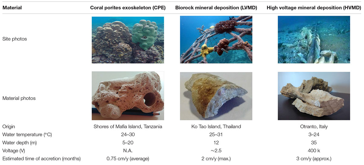
Table 1. The investigated calcium babonates and their origin. For HVMD, Underwater Photo—by S.T.E.S. (Sub Techinal Edil Service).
While the CPE grows naturally under the calcification process of the corals, LVMD and HVMD are manmade, with the first being a controlled process and the second, uncontrolled. The CPE is a reef building coral and includes different species growing in tropical waters. It is reported that it grows its skeleton about the central axis between 0.3 and 1.2 cm/y in average, depending on location, climate and colony type (Elizalde-Rendon et al., 2010; Neviaty et al., 2016; Tortolero-Langarica José de Jesús et al., 2016).
The Biorock technology precipitates calcium carbonate over the cathode establishing a direct current between two electrodes in sea water (typically 1.2–2.5 V). Besides the applied potential, the main parameters affecting the accretion are water temperature, pH, conductivity, and suspended sediments. The reduction of water taking place at the cathode results in an increase of pH close to the cathode surface. When the pH increases the carbonate equilibrium is shifted toward carbonate (CO32–), and CaCO3 precipitates at the surface of the electrode (Karoui et al., 2013). CaCO3 can form two different polymorphs at typical seawater conditions: aragonite and calcite. Preliminary experiments have shown that increasing the current above a certain level results in electrodeposition of magnesium hydroxide [Mg(OH)2, brucite] rather than CaCO3. Naturally, brucite is also often found in association with calcite and aragonite. The deposition of brucite takes place when the pH of the surface of the electrode reaches 9.2 (Barchiche et al., 2004). Despite the reported growth rates of Biorock varying significantly depending on conditions, it is clear that a well-functioning installation in warm waters (such as the one from where LVMD was taken) can have growth rates up to 2 cm/y (Goreau and Prong, 2017; Margheritini et al., 2020).
HVMD, in this case, resulted from parasitic currents after the probable disappearance of insulation of the high voltage Italy-Greece submarine power cable (max tension = 400 k Volts). While the water temperatures in the cases of CPE and LVMD correspond to warm tropical shallow waters, the formation of HVMD occurred in deeper and cooler waters in the Mediterranean Sea. The growth rate was estimated based on the observations made after monitoring: a 6 cm accretion was formed after roughly 2 years.
We investigated a wide array of physical and chemical properties for the two artificially developed materials compared to natural coral reef. The selected properties were deemed relevant for potentially applying the materials in coral reef repair including supporting an bioactive marine ecosystem at the reef. Chemical and mineralogical composition, internal and external surface areas, pore structure and size distribution, material structure and densities, and mechanical strength were obtained using state-of-the-art measurement and visualization methods, Table 2 and Figure 1.
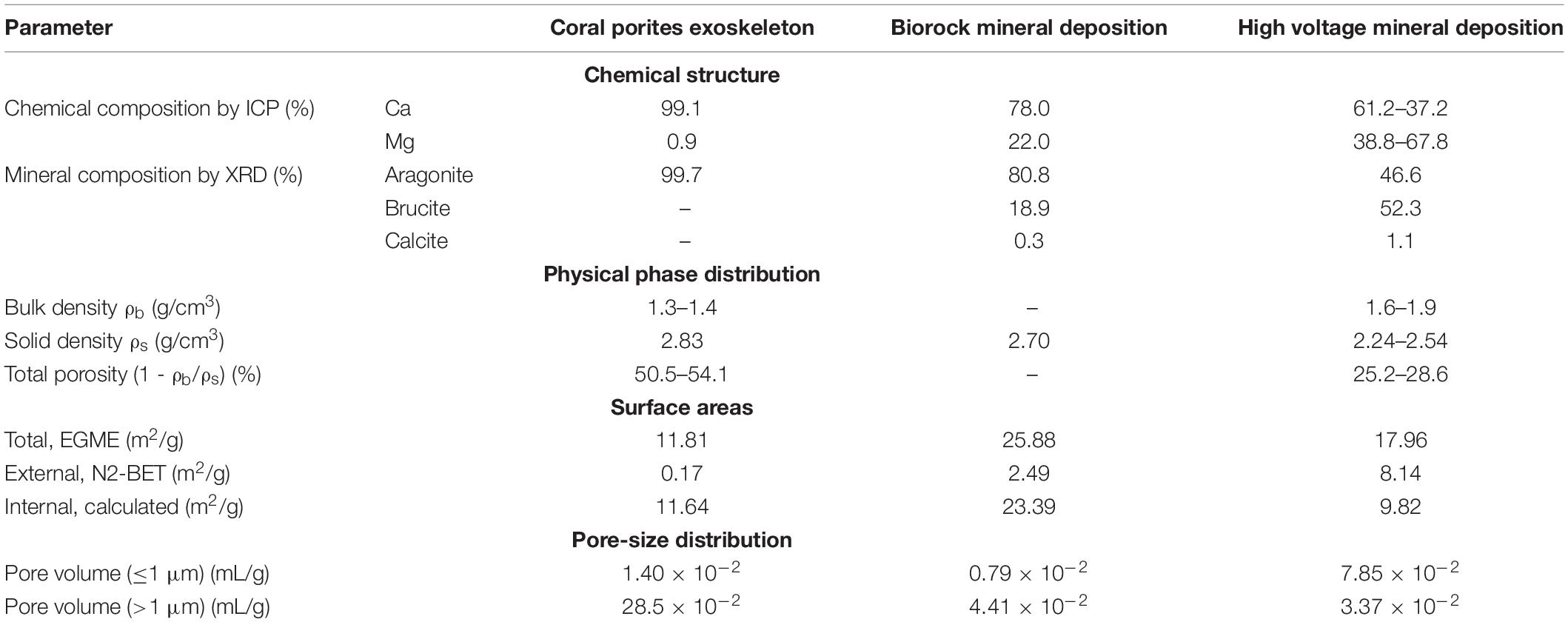
Table 2. Physical-chemical properties of CPE, LVMD, and HVMD.
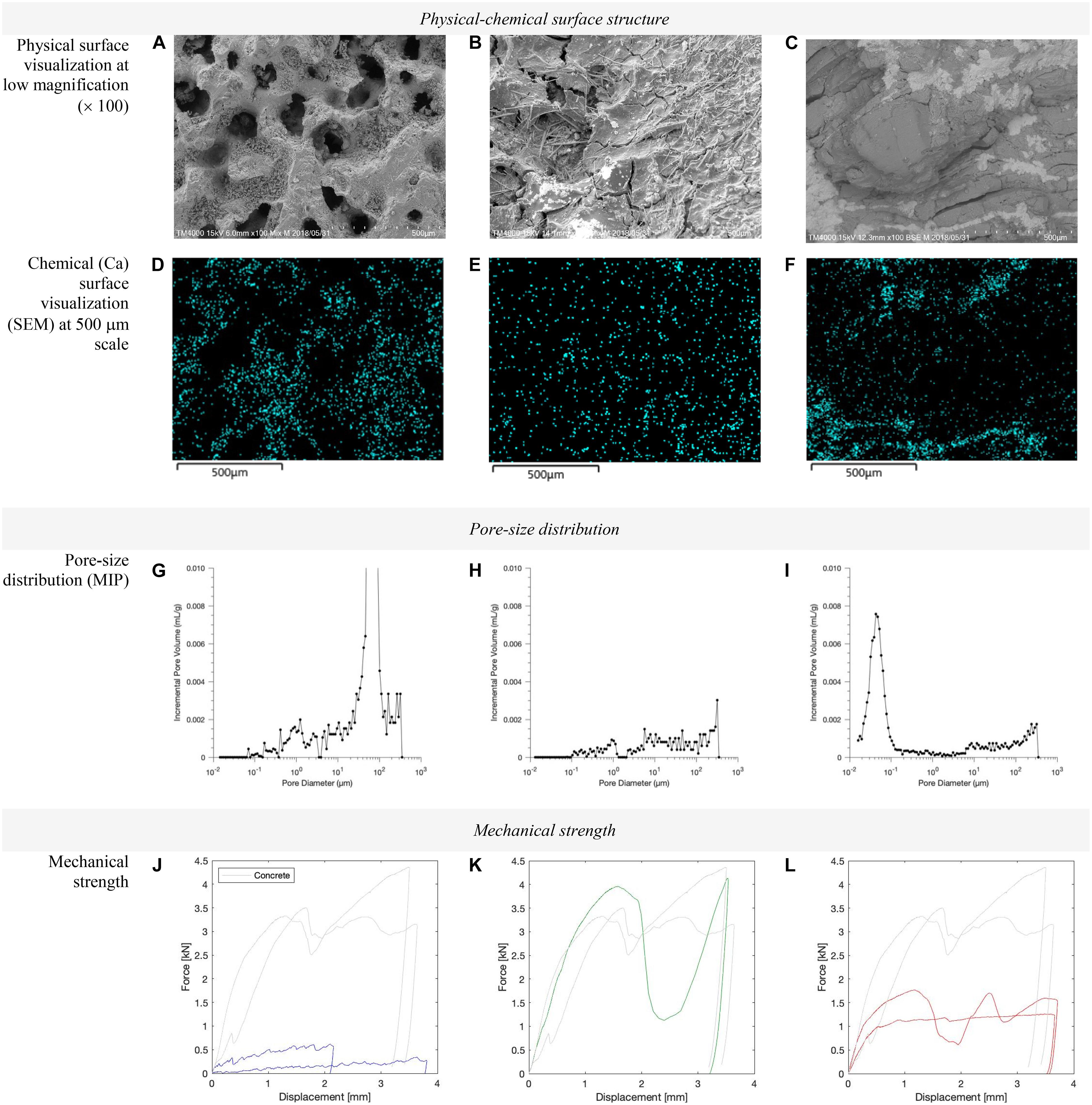
Figure 1. Surface Structure of CPE (A,D,G,J), LVMD (B,E,H,K), and HVMD (C,F,I,L).
Physical-Chemical Structure
The physical and chemical structure of the three materials was investigated through the following parameters:
a. Contents of chemical compounds and mineral composition.
b. SEM imaging.
c. Chemical surface distribution.
The calcomagnesian compounds differ in their chemical composition: CPE shows 99.1% Calcium and 0.9 Magnesium; LVMD 78% Calcium, 22% Magnesium and HVMD a variable 37–61% of Calcium and 68–39% of Magnesium, respectively. The chemical composition reflects directly in the mineral composition where CPE being 99.7% aragonite; LVMD 80.8% aragonite, 18.9% brucite and 0.3% calcite; and HVMD 46.6% aragonite, 52.3% brucite, and 1.1% calcite. It is expected that the chemical and mineral compositions have an influence on the strength of the materials, disclosing details on the different hardness of the minerals present in the samples: while brucite is 2.5–3 in hardness from the Mohs scale, calciate is 3 and aragonite features 3.5–4, being the hardest of the three minerals.
Scanning Electron Microscopy (SEM) images at × 100 magnification show the perforated surface of the CPE shaped by the corallites which are the circular system of holes forming a skeletal cup, made by an individual stony coral polyp, that are circa 1,500 μm in diameter. These are clearly not present in the LVMD and HVMD because they haven’t been formed by hard corals polyps but by precipitation of minerals induced under electrolysis of seas water. Therefore, they feature a smoother surface with fissures. Zooming into ×5,000 magnification in Supplementary Appendix we can notice crystals from all the samples, with particularly big prismatic crystal in the LVMD and small one in the HVMD sample, and acicular crystals for CPE. In literature, the mineral structure of Coral Porites was studied in detail, revealing a complex growing mechanisms influenced by the day and night light cycles. Three distinct regions were defined in the mineral orientation: (1) randomly orientated granular, porous nanocrystals; (2) partly oriented nanocrystals which were more granular and porous; and (3) densely packed aligned needle-like crystals. The first type would be produced during the day, while at night the calcification process slows down and generates long aligned needles forming an acicular habit (van de Locht et al., 2013).
The chemical surface visualization for Calcium confirms the results of the chemical composition analysis and reveals a more homogeneous distribution for CPE and LVMD than HVMD.
Physical Phase Distribution and Surface Area
The Physical phase distribution of the three materials was investigated through the parameters:
d. Bulk density.
e. Solids density.
f. Total porosity.
The CPE has the highest solids density (2.83 g/cm3) followed by the LVMD (2.70 g/cm3). The HVMD material is the material with lowest density (2.24–2.54 g/cm3). The difference between the two artificial materials is caused by the speed of the process for mineral deposition under sea water electrolysis. In the case of LVMD the process is slow at very low voltages, and, this results in a denser product. In case of HVMD, the process happens with excess energy, higher electrical currents and more rapidly, resulting in the deposition of more brucite and less aragonite and a much lower density. CPE, on the other hands, has a solid density closer to the one of LVMD. Measurements of the bulk density and total porosity are present only for CPE and HVMD because the sample of LVMD was too small to have comparable results with the other two specimens (for the bulk density 1 cm3 of material was carved, dried in the oven and weighed). Nevertheless, the bulk density of HVMD is higher than the one of CPE, supposedly because of the macropores.
The bulk density of CPE is lower than HVMD (1.3–1.4 g/cm3 vs. 1.6–1.9 g/cm3) and the total porosity is instead consistently higher (50.5–54.1% vs. 25.2–28.6%). The LVMD appears to have a very high bulk density and consequently a relatively low total porosity.
The surface areas where investigated by mean of:
g. Total specific surface area.
h. External specific surface area.
i. Internal calculation.
We used the retention of Ethylene Glycol Monoethyl Ether (EGME) for the adsorption of polar liquids probing the total surface area together with the physisorption of nitrogen gas (BET-N2) for the gas adsorption methods, yielding the external surface area of the mineral particles. For the BET-N2, if the material has intracrystalline porosity, then the measured surface area should be independent of the particle size, since the surface area of the pores will prevail. If the material has little or no intracrystalline porosity, then there may be a particle-size dependence, which is strongest at the smallest sizes. Total surface area can show a significant influence on many physical and chemical properties of materials. In addition to cation exchange capacity and absorption, it may be the dominant factor in controlling their mechanical behavior.
The total surface area measured with EGME shows the largest area for the LVMD (25.88 m2/g), followed by the HVMD (17.96 m2/g) and the smallest area corresponding to the CPE (11.81 m2/g). Samples with high total surface area have high water holding capacities, or in other words, increased adsorption capacities.
The highest external surface area is clearly found in the HVMD (8.14 m2/g), followed by the LVMD (2.49 m2/g) and CPE (0.17 m2/g). By calculation, the internal area is 11.64 m2/g for CPE, 23.39 m2/g for LVMD and 9.82 m2/g for HVMD. This shows a large ratio of internal-to-external surface area in CPE and LVMD in comparison to HVMD.
For porous materials, the external surface area is negligible compared to the internal one. As mentioned, this is the case for the coral sample. Closed pores have no relevance for surface phenomena and they influence only the bulk density. Nitrogen adsorption and BET is then the only way to obtain the surface area of porous materials when interconnection of pores is present, taking into account that it overestimates values when micropores are present. The effective porosity is, in this sense, the total porosity less the isolated porosity. In the CPE, all the pores are interconnected.
Pore-Size Distribution
The pore size distribution was investigated by mean of:
j. Mercury Intrusion Porosimetry (MIP).
This determines the volume of open pores between 0.006 and 360 μm together with the pore entrance size distribution. Corals porites have an average pores size distribution of 200–250 μm. In this study, the pore volumes are observed in the microporous (≤1 μm) and macroporous (>1 μm) regions. As Table 2 shows, CPE yields the highest pore volumes: 1.40⋅10–2 mL/g for pores ≤1 μm and 28.5⋅10–2 mL/g for pores >1 μm, showing significantly large pores in the macroporous region. This is caused by the large volume of pores in the 40–100 μm region, as seen in Figure 1. The pores are reasonably interconnected as they have been formed by the polyps during their lives and growth. By comparison, the LVMD shows a pore volume 0.79⋅10–2 mL/g for pores ≤1 μm and 4.41⋅10–2 mL/g for pores >1 μm while the HVMD features, respectively, 7.85⋅10–2 mL/g and 3.37⋅10–2 mL/g. While LVMD displays an even pore-size distribution, which is known to improve the strength of a material, HVMD displays more uneven majority of pore volumes in the respective <0.1 μm and >10 μm ranges. The pore-size distributions are visually demonstrated in the SEM images in Figure 1, which clearly exhibit the macropores present in CPE. The cumulative size-distribution of the pores may be observed in Supplementary Appendix.
Mechanical Strength
The mechanical strength is a very interesting parameter to consider because it relates to one of the most important functions of reefs, which is the coastal protection function and therefore the ability to withstand wave forces. In the tests, we compared a standard 3.5 kN concrete with our three materials [Concrete with compressive strength of 25 MPa, corresponding to a compressive strength class C20/25 (British Standards Institution, 2013)]. The strength is determined based on scaled down compression test—puncture resistance. Results given in kN as function as displacement. Standard compression is given in MPa = N/mm2 as function of displacement. The outcomes of these tests confirm the results from Doctor H. Hilbertz Wolf with LVMD indicating a compression strength above 3.5 kN; additionally, CPE show the lower resistance to compression followed by HVMD with a compression strength just above 1 kN, i.e., 3 times smaller than the stronger samples. These results can be correlated to the investigated pore-size distributions, including the large presence of macropores in CPE and uneven pore-size distribution in HVMD.
Discussion
The material between the macro-pores in the CPE is denser (2.83 g/cm3 vs. 2.24–254 g/cm3) and harder (aragonite vs. brucite) than the one between the fractures and porosities of the HVMD sample.
The pore size distribution differs in the three materials: while CPE and LVMD are similar in the sense that their pore volumes ≤1 μm are smaller than the pore volumes > 1 μm; the opposite is true for the HVMD sample. Again, this again might be partially explained by the different conditions (and speeds) in which the two artificial materials were formed. It is interesting to notice that while CPE presents a peak just before 100 μm, HVMD has a peak (even if smaller) just before 0.1 μm; LVMD has a much more uniform pore size distribution compared to the other two materials. Indeed, the rapid-growth marine deposit showed a more bimodal pore-size distribution (micro- and macropores, almost no connecting meso-pores) and different mineral composition, which may affect both ecosystem functions and large-scale strength.
The pore size distribution can be connected to the mechanical properties of the materials, but other functions related to the ecosystem health may also be influenced by it. For example, it is known that many reef-building corals have evolved in tight symbiosis with photosynthetic algae that live in their tissues. The exoskeleton has therefore the function of growing toward sun light and, by some more recent studies, at the same time, absorbing ultraviolet radiation that could induce tissue damage while reflecting the photosynthetic active radiation (Reef et al., 2009). This seem to be a property of calcium carbonate and its structure. Additionally, the ability of a material to be colonized by marine life and therefore its sustainability, is also determined by its pore size distribution.
Conclusion
We have identified the properties that could promote the use of electrochemical deposited materials (LVMD or HVMD) for (artificial) submerged reefs with the dual function of restoration of marine environments and coastal protection. These properties are: physical-chemical structure, phase distribution and surface area, pore-size distribution and mechanical strength. We hypothesize that the artificial materials analyzed can combine both ecological and engineering school of thought as they can be designed to be the very similar to coral reefs (the quintessential natural coastal protection system) in shape and size, to even mimic porosity, mineral composition, surface roughness and mechanical strength. Additionally, by tuning the applied electrical voltage it should be possible to obtain a rapid grown but less strong reef mainly composed by brucite, while when allowing more time and lower voltage, a stronger deposition of calcite and aragonite would occur.
While no significant differences were found between the two electrodeposited artificial materials and coral Porites in terms of physical and chemical properties, it must be noticed the compression strength of the artificial materials is significantly higher than the one of coral Porites. Chemical and mineral compositions do not have the only influence on the strength of the materials: HVMD with higher percentage of brucite, less hard than calcite and aragonite (hardest), in compression tests showed weaker mechanical resistance than LVMD, but not than CPE; in fact, CPE is the weakest of the three materials despite having the highest percentage of aragonite. A concurring and seemingly more important parameter is the pore size distribution, where even pore-size distribution promotes material resistance. In this respect, LVMD has the best resistance and the most even pore size distribution and only the second higher percentage of hardest material, aragonite. HVMD showed a more bimodal pore-size distribution and different mineral composition, which may affect ecosystem functions and strength. Thus, a combination of rapid-growth and slow-growth processes is likely necessary for timely combined applications of artificial reefs for habitat restoration and coastal protection. The key aspect of their compatibility with the marine environment lays in their chemical and mineral composition, mostly calcium carbonate and aragonite. The success of the material for colonization by benthic communities (widely documented in the literature), had been hypnotized to be hidden in the capability of the electrical current of stimulating biological growth (Kihara et al., 2018), as well as in the similarity of the chemical and mineral composition to natural corals and hard shell marine organisms, the surface porosity that facilitate larvae settlement. This study also sheds some light into these hypothesis adding further knowledge into the material structures and their similarities at micro and macro levels.
More importantly, these artificial materials could be applied in the realization of artificial reefs in full respect of the guidelines of the 2009 London Convention and Protocol/UNEP regarding the rightness of materials for artificial reefs. The restoration abilities of these applications reported in literature indicate that such installations could generate an enhancement of the ecosystem that goes beyond restoration of pre-existing conditions. LVMD and HVMD are inert as long as there is an ongoing electrolysis process that maintains the precipitations rates of calcium carbonate over the cathode. Nevertheless, even in case of discontinuity of the process, the dissolution of calcium carbonate mimics very closely the natural processes of dissolution of coral and shells that happens in the ocean.
Finally, the acquisition of such a practice for artificial reefs could open the road for even more advantages in some areas in the World. For example, where the management of surplus electricity generation from renewable energy is an issue. Therefore, we recommend further testing and development for the application of electrochemical deposition for coastal management, restoration and protection strategies.
Materials and Methods
A broad set of analysis has been performed on the three samples in order to characterize their mechanical properties, chemical composition and structure. Apparatuses used in this study are listed in Table 3, indicating the material property subject of the specific investigation, the reference method used and the sample size and quality necessary for the analysis.
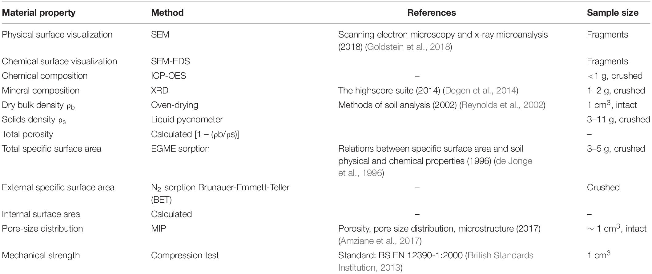
Table 3. Methods used for the characterization of CPE, LVMD, and HVMD.
• Scanning Electron Microscropy (SEM) with Energy-Dispersive X-ray Spectroscopy (EDS) Mapping. SEM is an imaging technique used to investigate material composition and surface topography. Signals of secondary electrons give information on surface topography, such as surface roughness and uniformity, while backscattered (secondary) electrons identify contaminants on the surface. Small samples of approximately 1 cm3 are used to conduct the measurements. The SEM measurements were conducted at two magnifications: ×100 and ×5,000. EDS enables subsequent characterization of surface distribution by reading peaks on the electro-magnetic emission spectrum.
• ICP-OES (Inductively coupled plasma—optical emission spectrometry) was used to determine the chemical composition of the samples. Samples are acidified preferably with 1–5% HNO3 in order to keep metals in solution and as solid materials destructed with nitric acid only (concentration HNO3 below 10%, ideally 1%), or if necessary with HNO3/H2O. This step can be performed as a closed destruction in a microwave-oven. Each element has an own characteristic emission spectrum that is measured with a spectrometer. The light intensity on the wavelength is measured and with the calibration calculated into a concentration.
• X-ray diffraction (XRD) was used to examine the crystal structure of the different materials. The XRD spectra (Figure 2) were obtained using an Aeris Powder diffractometer form Panalytical fitted with a Ni-filter and Cu Ka radiation source (λ = 1.54 Å). The diffraction patterns were recorded in the 2θ interval 15°–65°. The HighScore Plus software package was used to perform Rietveld refinement deconvoluting the XRD patterns in order to obtain quantitative data for the composition.
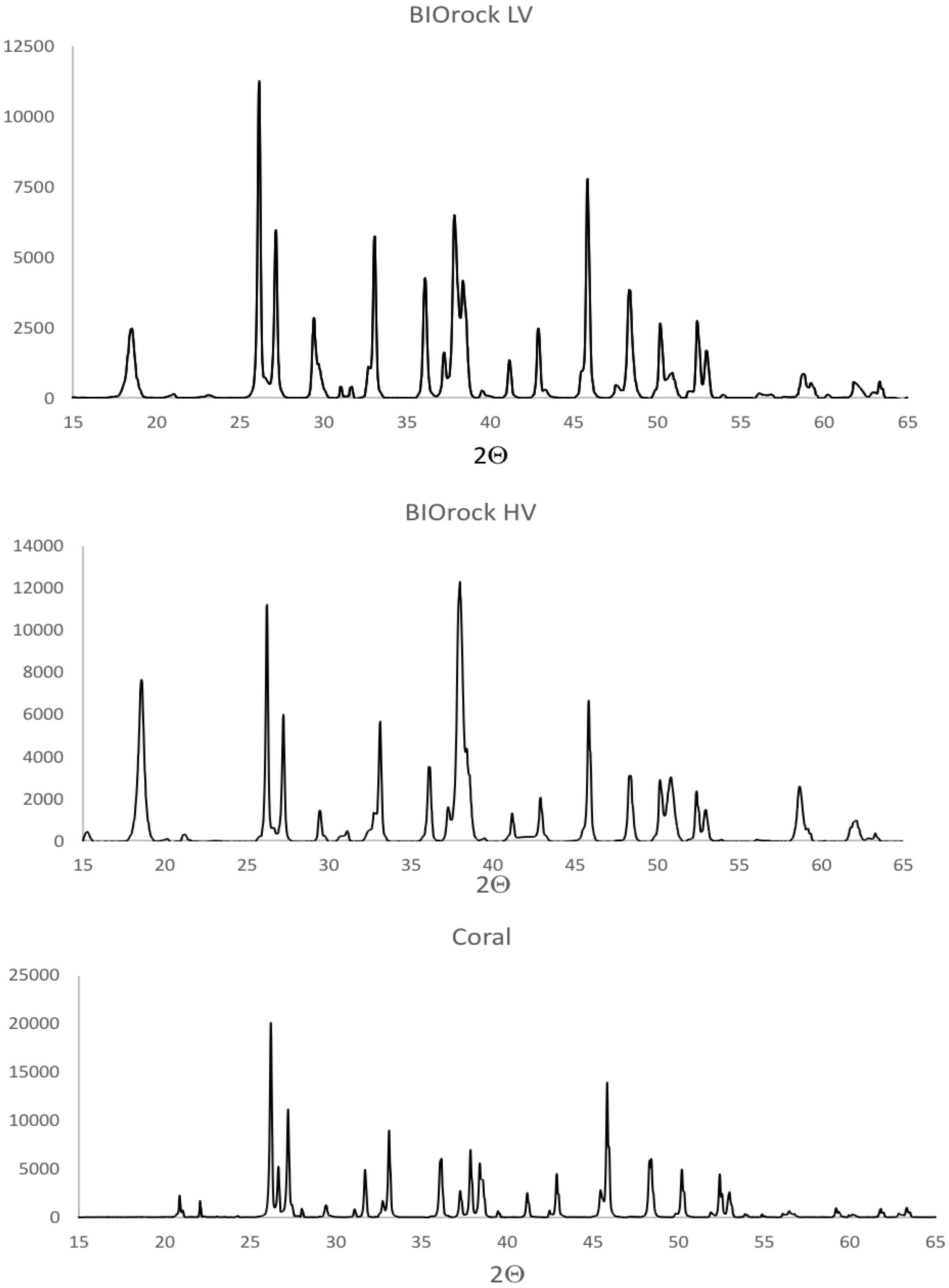
Figure 2. XRD profiles and patterns for the three materials.
• Phase distribution: dry bulk density ρb is the natural (in-situ) density of the material including voids, and describes the compaction level of the material (g solids/cm3 intact material). Solids density ρs is the density of the pure solids (excluding voids, a material constant), g solids/cm3 solids. From this, the total porosity (volume content of pores or voids) of the material can be calculated as Φ = 1 – (ρb/ρs) cm3 voids/cm3 intact material.
• Total, water-active (hydratable), and external surface areas of the materials (SA_EGME, SA_H2O, and SA_N2, m2/g dry material) were measured by gas adsorption, using EGME, water vapor, and nitrogen (N2) as the sorbing gases. Pore size distribution and content of micro- and meso-pores were measured by low-pressure mercury intrusion porosimetry. All basic physical characterization measurements were carried out by international standard methods for soil and sediment materials (Kihara et al., 2018). It is noted that water-active surface area is calculated from a water vapor sorption isotherm at 20% relative humidity, partial water vapor pressure of p/po = 0.2, and normally the water vapor and EGME sorption methods agree well in regard to describing total specific surface area of different clay, soil and sediment materials (Quirk and Murray, 1999).
• Mercury Intrusion Porosimetry (MIP): Pore size distributions and the content of micro- and mesopores are achieved by the low-density mercury intrusion porosimetry (MIP). The method is limited to pores above 3.5 nm. MIP is a non-intrusive method that does not wet the material due to high contact angles. Air is removed from the material sample applying a vacuum, where-after the sample is gradually penetrated with mercury at low pressures so as not to damage the structure of the sample. Pressure is increased in steps, while the incremental mercury volume in the porous media is measured, allowing the distribution of the pore sizes to be determined.
• Mechanical strength for all samples was determined using adapted approach to compression test. Due to the small amount of LVMD sample it could be subjected only to scaled down compression test (puncture resistance test). The test consisted of small piston continuously applying force to the sample, which is casted in a concrete matrix. The applied force and displacement are simultaneously logged to obtain the resistance as the maximum applied force before breaking. To validate the test, a standard concrete of compression class C20/25 was tested under standard testing conditions (prisms with dimensions of 4 × 4 × 4 cm), as well as, 1 × 1 × 1 cm concrete and HVMD samples, using standard compression equipment.
Data Availability Statement
The raw data supporting the conclusions of this article will be made available by the authors, without undue reservation.
Author Contributions
LM: EUDP project coordinator, CPE and LVMD samples collection, compression tests, bulk densities, ICP analysis, writing and editing the manuscript, and conceptualization. PM: coordinated the Danish-Japanese measurement program and participated in writing the manuscript. RJ: planning the compression tests and participated in writing the manuscript. KF: pore size distributions analysis, solid densities, SEM rendering, and writing the manuscript. YA: planning, execution and analysis of the mechanical strength, participation in writing/giving feedback to mechanical strength sections, and rendering. KK: SEM tests. LJ: total specific and external specific surface area analysis, solid densities, and participated in editing of the text. RV: LVMD sample collection and participated in editing of the text. TB: XRD samples analysis. MS: EUDP project coordinator, XRD samples analysis, and participated in editing of the text. All authors contributed to the article and approved the submitted version.
Funding
The authors thank EUDP (Energy Technology Development and Demonstration Program) for supporting the research on application of the mineral deposition technology within the project “New material for marine substructures” (Grant No. 50520010).
Conflict of Interest
The authors declare that the research was conducted in the absence of any commercial or financial relationships that could be construed as a potential conflict of interest.
The reviewer PF declared a shared affiliation with several of the authors, LM, PM, RJ, KF, YA, TB, and MS, to the handling editor at the time of review.
Acknowledgments
We want to thank Thomas Goreau for his inspirational research.
Supplementary Material
The Supplementary Material for this article can be found online at: https://www.frontiersin.org/articles/10.3389/fmars.2021.652986/full#supplementary-material
References
Amziane, S., Collet, F., Lawrence, M., Magniont, C., Picandet, V., and Sonebi, M. (2017). Recommendation of the RILEM TC 236-BBM: characterisation testing of hemp shiv to determine the initial water content, water absorption, dry density, particle size distribution and thermal conductivity. Mater. Struct. 50:167. doi: 10.1007/978-94-024-1031-0
Barchiche, C., Deslouis, C., Gil, O., Refait, P., and Tribollet, B. (2004). Characterisation of calcareous deposits by electrochemical methods: role of sulphates, calcium concentration and temperature. Electrochim. Acta 49, 2833–2839. doi: 10.1016/j.electacta.2004.01.067
British Standards Institution (2013). EN 206:2013 + A1:2016(E) Concrete – Specification, Performance, Production and Conformity. London: British Standards Institution.
Burke, L., Reytar, K., Spalding, M., and Perry, A. (2011). Reefs at Risk Revisited. Available online at: https://digitalarchive.worldfishcenter.org/handle/20.500.12348/1107 (accessed April 19, 2019).
de Jonge, L., Moldrup, P., Jacobsen, O., and Rolston, D. (1996). Relations between specific surface area and soil physical and chemical properties. Soil Sci. 161, 9–21. doi: 10.1097/00010694-199601000-00003
Degen, T., Sadki, M., Bron, E., König, U., and Nénert, G. (2014). The highscore suite. Powder Diffr. 29, S13–S18. doi: 10.1017/S0885715614000840
Elizalde-Rendon, E. M., Horta-Puga, G., Gonzalez-Diaz, P., and Carricart-Ganivet, J. P. (2010). Growth characteristics of the reef-building coral porites astreoides under different environmental conditions in the Western Atlantic. Coral Reefs 29, 607–614. doi: 10.1007/s00338-010-0604-7
European Commission (2007). Interpretation Manual of European Union Habitats. Available online at: https://ec.europa.eu/environment/nature/legislation/habitatsdirective/docs/2007_07_im.pdf (accessed March 29, 2019).
Fabi, G., Scarcella, G., Spagnolo, A., Bortone, S. A., Charbonnel, E., Goutayer, J. J., et al. (2015). Practical Guidelines for the Use of Artificial Reefs in the Mediterranean and the Black Sea. FAO Studies and Reviews. General Fisheries Commission for the Mediterranean No. 96. Rome: FAO.
Ferrario, F., Beck, M. W., Storlazzi, C. D., Micheli, F., Shepard, C. C., and Airoldi, L. (2014). The effectiveness of coral reefs for coastal hazard risk reduction and adaptation. Nat. Commun. 5:3794. doi: 10.1038/ncomms4794
Frieler, K., Meinshausen, M., Golly, A., Mengel, M., Lebek, K., Donner, S. D., et al. (2013). Limiting global warming to 2°C is unlikely to save most coral reefs. Nat. Clim. Change 3, 165–170. doi: 10.1038/nclimate1674
Gallop, S. L., Young, I. R., Ranasinghe, R., Durrant, T. H., and Haigh, I. D. (2014). The large-scale influence of the great barrier reef matrix on wave attenuation, coral reefs. Coral Reefs 33, 1167–1178. doi: 10.1007/s00338-014-1205-7
Goldstein, J. I., Newbury, D. E., Michael, J. R., Ritchie, N. W. M., Scott, J. H. J., and Joy, D. C. (2018). Scanning Electron Microscopy and X-Ray Microanalysis, 4th Edn. New York: Springer. doi: 10.1007/978-1-4939-6676-9
Goreau, J. T., and Prong, P. (2017). Biorock electric reefs grow back severely eroded beaches in months. J. Mar. Sci. Eng. 5:48. doi: 10.3390/jmse5040048
Goreau, T. J. (2014). Electrical stimulation greatly increases settlement, growth, survival, and stress resistance of marine organisms. Nat. Resour. 5, 527–537. doi: 10.4236/nr.2014.510048
Hilbertz, W. H. (1979). Electrodeposition of minerals in seawater. IEEE J. Coast. Eng. 4:78. doi: 10.1109/OCEANS.1978.1151134
Hoegh-Guldberg, O. (2012). The adaptation of coral reefs to climate change: is the Red Queen being outpaced? Sci. Mar. 76, 403–408. doi: 10.3989/scimar.03660.29A
Karoui, H., Riffault, B., Jeannin, M., Kahoul, A., Gil, O., Amor, M. B., et al. (2013). Electrochemical scaling of stainless steel in artificial seawater: role of experimental conditions on CaCO3 and Mg(OH)2 formation. Desalination 311, 234–240. doi: 10.1016/j.desal.2012.07.011
Kihara, K., Hosokawa, Y., Koibuchi, Y., Yamamoto, S., and Kondo, Y. (2018). Studies on growth-nets of reef-building corals by galvanic method for corals (GMC). J. Japan Soc. Civil Eng. Ser. B3 74, I_330–I_335. doi: 10.2208/jscejoe.74.I_330
Lenton, T. M., Rockström, J., Gaffney, O., Rahmstorf, S., Richardson, K., Steffen, W., et al. (2019). Climate tipping points – too risky to bet against. Nature 575, 592–595. doi: 10.1038/d41586-019-03595-0
Logan, C. A., Dunne, J. P., Eakin, C. M., and Donner, S. D. (2014). Incorporating adaptive responses into future projections of coral bleaching. Glob. Chang. Biol. 20, 125–139. doi: 10.1111/gcb.12390
Mallela, J., and Perry, C. T. (2007). Calcium carbonate budgets for two coral reefs affected by different terrestrial runoff regimes, Rio Bueno, Jamaica. Coral Reefs 26, 129–145. doi: 10.1007/s00338-006-0169-7
Margheritini, L., Colaleo, G., Contestabile, P., Bjørgård, T. L., Simonsen, M. E., Lanfredi, C., et al. (2020). Development of an eco-sustainable solution for the second life of decommissioned oil&gas platforms: the mineral accretion technology. Sustainability 12:3742. doi: 10.3390/su12093742
Neviaty, P. Z., Arman, A., and Lalang. (2016). The growth rate of coral porites lutea relating to the El Niño Phenomena at Tunda Island, Banten Bay, Indonesia. Procedia Environ. Sci. 33, 505–511. doi: 10.1016/j.proenv.2016.03.103
Perry, C., Murphy, G., Kench, P. S., Smithers, S. G., Edinger, E. N., Steneck, R. S., et al. (2013). Caribbean-wide decline in carbonate production threatens coral reef growth. Nat. Commun. 4:1402. doi: 10.1038/ncomms2409
Quirk, J. P., and Murray, R. S. (1999). Appraisal of the ethylene glycol monoethyl ether method for measuring hydratable surface area of clays and soils. Soil Sci. Soc. Am. J. 63, 839–849. doi: 10.2136/sssaj1999.634839x
Reef, R., Kaniewska, P., and Hoegh-Guldberg, O. (2009). Coral skeletons defend against ultraviolet radiation. PLoS One 4:e7995. doi: 10.1371/journal.pone.0007995
Reynolds, D., Elrich, D. E., Young, E. G., Amoozegar, A., Booltink, H. W. G., and Bouma, J. (2002). Methods of soil analysis, part 4: physical methods. Soc. Sci. Soc. Am. J.
Sabatier, F. (2002). Coastal Engineering Manual (CEM), Engineer Manual 1110-2-1100. Washington, DC: U.S. Army Corps of Engineers. doi: 10.4000/mediterranee.201
Sheppard, C., Dixon, D. J., Gourlay, M., Sheppard, A., and Payet, R. (2005). Coral mortality increases wave energy reaching shores protected by reef flats: examples from the Seychelles. Estuarine Coast. Shelf Sci. 64, 223–234. doi: 10.1016/j.ecss.2005.02.016
Støttrup, J. G., Stenberg, C., Dahl, K., Kristensen, L. D., and Richardson, K. (2014). Restoration of a temperate reef: effects on the fish community. Open J. Ecol. 4, 1045–1059. doi: 10.4236/oje.2014.416086
Tortolero-Langarica José de Jesús, A., Cupul-Maga na Amílcar, L., Carricart-Ganivet Juan, P., Mayfield Anderson, B., and Rodríguez-Troncoso Alma, P. (2016). Differences in growth and calcification rates in the reef-building coral porites lobata: the implications of morphotype and gender on coral growth. Front. Mar. Sci. 3:179. doi: 10.3389/fmars.2016.00179
Vaccarella, R., and Goreau, T. J. (2012). “Restoration of seagrass mats (Posidonia oceanica) with electrical stimulation,” in Innovative Methods of Marine Ecosystem Restoration, eds T. J. Goreau and R. K. Trench (Boca Raton, FL: CRC Press), 161–167. doi: 10.1201/b14314-15
van de Locht, R., Verch, A., Saunders, M., Dissard, D., Rixen, T., Moya, A., et al. (2013). Microstructural evolution and nanoscale crystallography in scleractinian coral spherulites. J. Struct. Biol. 183, 57–65. doi: 10.1016/j.jsb.2013.05.005
Whalan, S., Abdul Wahab, M. A., Sprungala, S., Poole, A. J., and de Nys, R. L. (2015). Larval settlement: the role of surface topography for sessile coral reef invertebrates. PLoS One 10:e0117675. doi: 10.1371/journal.pone.0117675
Keywords: electrochemical deposition, electrolysis, reef restoration, porosity, density, surface area, mechanical strength
Citation: Margheritini L, Møldrup P, Jensen RL, Frandsen KM, Antonov YI, Kawamoto K, de Jonge LW, Vaccarella R, Bjørgård TL and Simonsen ME (2021) Innovative Material Can Mimic Coral and Boulder Reefs Properties. Front. Mar. Sci. 8:652986. doi: 10.3389/fmars.2021.652986
Received: 13 January 2021; Accepted: 27 May 2021;
Published: 23 June 2021.
Edited by:
Hajime Kayanne, The University of Tokyo, JapanReviewed by:
Makoto Omori, Makoto Omori, JapanBarbara Zanuttigh, University of Bologna, Italy
Peter Frigaard, Aalborg University, Denmark
Luca Martinelli, University of Padova, Italy
Copyright © 2021 Margheritini, Møldrup, Jensen, Frandsen, Antonov, Kawamoto, de Jonge, Vaccarella, Bjørgård and Simonsen. This is an open-access article distributed under the terms of the Creative Commons Attribution License (CC BY). The use, distribution or reproduction in other forums is permitted, provided the original author(s) and the copyright owner(s) are credited and that the original publication in this journal is cited, in accordance with accepted academic practice. No use, distribution or reproduction is permitted which does not comply with these terms.
*Correspondence: Lucia Margheritini, bWx1Y0BidWlsZC5hYXUuZGs=