 Zhengzhi Deng
 Pinjie Wang
 Pengda Cheng2*
- 1Ocean College, Zhejiang University, Zhoushan, China
- 2Institute of Mechanics, Chinese Academy of Sciences, Beijing, China
To share the construction and maintenance cost, an asymmetric oscillating water column (OWC) device integrated with a pile-fixed box-typed offshore breakwater is considered experimentally and numerically. A fully nonlinear numerical wave tank is established and validated with the open source solver OpenFOAM. The effects of the width and draft of rear box, and the incident wave height on the wave energy conversion efficiency, reflection and transmission coefficients, and energy dissipation coefficient are examined. In addition, the superiority of the present coupling system, compared to the traditional box-type breakwater, is discussed. With well comparisons, the results show that the existence of the rear breakwater is beneficial for the formation of partial standing waves and further wave energy conversion. In the range of wave heights tested, the higher the incident wave height, the larger the energy absorption efficiency except for the short-wave regimes. Moreover, the OWC-breakwater coupling system can obtain a similar wave blocking ability to the traditional one, and simultaneously extract wave energy and decrease wave reflection.
1. Introduction
The growing interest in the conversion and utilization of ocean wave energy source can be traced back to one century ago, since when various forms of wave energy extraction technologies began to appear (Falcão, 2010; You et al., 2010; Qiu et al., 2019). Since the 1980s, the tendency of wave energy exploitation has shifted toward practical, commercial medium-sized devices for the energy supply of remote islands. The oscillating water column (OWC) wave energy converter (WEC) is considered to be one of the most widely used technologies for its simple structure, easy installation and maintenance, and non-corrosive mechanical components (Falcão, 2010; Heath, 2012), whose main working principle is that the air-chamber pressure fluctuation induced by the heave motion of interior water column feeds the generator mounted on the top to fulfill the energy conversion.
At an early stage, the study on OWC device is concentrated on the hydrodynamic performance and efficiency optimization in terms of the structural configuration of a stand-alone OWC device. Evans (1976) employed the ship-hydrodynamic theory to theoretically investigate the hydrodynamic properties of an OWC device by simplifying the internal water surface as a weightless piston. Later, Evans (1982) put forward the surface air pressure distribution theory and derived the expression of the optimal energy conversion efficiency of OWC devices. In order to further improve the hydrodynamic performance, in the literature, many scholars attempted to optimize the structural configuration of a single-air-chamber OWC device. Count and Evans (1984) suggested extending the side wall along the direction of wave incidence to expand the structure of air chamber and strengthen the wave-focusing effect. Deng et al. (2013) employed the matched eigenfunction expansion method to study the structure optimization of a coaxial structure-supported OWC device, and presented the optimal bottom opening in the range of π/2–5π/4. Extending the work by Deng et al. (2013) and Deng et al. (2014) further established a theoretical OWC model with a V-shaped channel at the bottom. They concluded that the existence of the V-shaped channel can significantly increase the conversion efficiency and widen the range of highly effective wave frequencies. Ashlin et al. (2016) focused on the configuration of the OWC bottom profile and presented that the device with a circular curve bottom profile has better performance. Vyzikas et al. (2017) compared the capability of OWC and U-OWC devices experimentally, and proposed preliminary opinions on how to optimize the structural form of traditional OWC devices. Ning et al. (2020a) carried out a numerical study on the influence of the thickness of the front wall of onshore U-OWC device, and the results indicated that when the thickness of the front wall increases, the efficiency of the OWC device will increase. Furthermore, Ning et al. (2020b) added a circle side wall to the outside of the single chamber OWC device, forming a structure of a dual chamber. The hydrodynamic performance of the cylindrical dual-chamber OWC device was experimentally and numerically investigated, and it was found that the efficiency of dual-chamber device was better than that of a single-chamber device.
To share the construction and maintenance cost, coupling OWC devices into other marine structures, such as breakwaters, is proposed and received much attention (Mustapa et al., 2017; Zhao et al., 2019; Zheng et al., 2019). Martins-Rivas and Mei (2009a,b) theoretically investigated the hydrodynamic performance and optimum absorption efficiency of an isolated OWC device mounted on a breakwater and a straight coast. Further, Lovas et al. (2010) considered an OWC device installed at a coastal corner under the framework of linear water wave theory. He et al. (2013) proposed a multi-functional floating rectangular breakwater mounted by two asymmetric OWC devices on both sides. They experimentally investigated the hydrodynamic performance and concluded that the integration is a viable option for cost-sharing between wave energy capturing devices and shore-protection structures, and thus enhance the cost-effectiveness of wave energy utilization. From an experimental and numerical point of view, Howe and Nader (2017) compared and discussed the hydrodynamic performances between the single OWC device and the OWC-breakwater coupling device, and discovered that the highly effective wave-frequency bandwidth of the coupling system is more than twice as the single one. On the basis of fully non-linear HOBEM model, Ning et al. (2019) predicted the hydrodynamic response of an OWC device over a stepped bottom, and the optimization scheme of step geometry and position was summarized. Deng et al. (2020) employed the open source platform OpenFOAM to deeply analyze the hydrodynamic performance of the offshore OWC device constructed on a rectangular underwater breakwater, and proposed an optimum structural configuration that can convert more wave energy over a wider wave–frequency range. Integrating the OWC device with a vertical tubular structure, Zheng et al. (2020) employed the matched eigenfunction expansion method to solve the problems of wave scattering and radiation under finite water depth. They found that a thinner chamber wall thickness offers benefits to wave power extraction in terms of a broader primary band of power capture factor response.
Most of the previous studies on the coupling systems of OWC and breakwater have focused on optimizing the structural shape of the OWC device, such as setting a U-type channel and a V-type opening, or finding the superior geometric dimensions of the OWC device, especially for the chamber width and opening ratio. The main concern of these studies is still the pneumatic efficiency of the OWC device, neglecting the wave dissipation and wave-blocking performance of the breakwater. When the size of the breakwater changes, it is challenging to maintain the overall hydrodynamic performance of the integrated system to an excellent level, that is, it can not only improve the wave energy extraction efficiency of the OWC device but also enable the breakwater to eliminate wave remarkably to create satisfactory navigation conditions.
In this paper, in order to block the wave transmission and simultaneously decrease wave reflection to improve the navigation safety of ships, an isolated OWC device equipped on the waveward side of a pile-fixed box-type breakwater is considered. Using the hybrid approach of experiments and numerical simulations, the effects of the structural parameters of the breakwater, such as the immersion depth, extended width, on the hydrodynamic performance (i.e., energy conversion coefficient, transmission, and reflection coefficients) are examined. In addition, the wave nonlinearity (wave height) is discussed. The article is structured as follows. The setup and information of experiment are presented in section 2. The computational principle and numerical method in OpenFOAM and wave generation toolbox waves2Foam are described in section 3. The verification and validation of the numerical model is discussed in section 4. Finally, the conclusions are drawn in section 5.
2. Experiment
2.1. Experimental Setup
The small-scale experiments were carried out in the wave flume at the Ocean Test Hall of Zhejiang University, China. The wave flume is 35 m long, 0.6 m wide, and its maximum water depth is 0.8 m. One end of the flume is fitted with a 1.5 m long piston-type wave-maker capable of generating both regular and irregular waves. At the other end of the flume, a 3 m long artificial beach is installed to absorb the outgoing wave. The OWC physical model is located in the middle of the flume and its front wall is 15.5 m away from the wave-maker. The width of the OWC model is equal to the flume in order to prevent wave diffraction, so that the experiments can be regarded as two-dimensional. The OWC physical model is made up of transparent Perspex sheets with thickness of 10 mm, as shown in Figure 1A, and the geometric sketch is illustrated in Figure 1B.
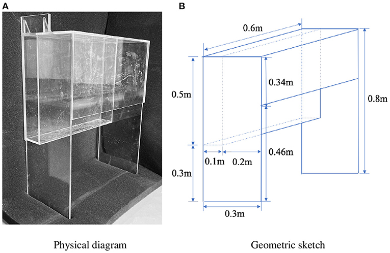
Figure 1. Schematic of the oscillating water column (OWC) model. (A) Physical diagram (B) Geometric sketch.
Figure 2 shows the experimental layout, including the locations of seven capacitance-type wave gauges (G1–G7) and two pressure transducers (S1, S2). The nearest gauge to the wave maker, G1, is to monitor the generated incident wave. The time series of surface elevations monitored by G2 to G4 is used to separate the incident and reflected waves based on the two-point method (Goda and Suzuki, 1976). G5 and G6 are used to record the free surface elevations inside the chamber. G7 is placed behind the structure to evaluate the transmission coefficient. In addition, two pressure transducers S1 and S2 are arranged below the orifice to monitor the relative pressure drop between the inside and outside of the chamber. In all tests, the data are collected by DJ800 data acquisition instrument of Tianjin Hydro-Technical Institute with 100 Hz sampling rate and 40 s duration time. In order to reduce the experimental uncertainty, experiments under each wave condition are repeated at least three times and the averaged value is taken as the final result. It is noted that, in this paper, to avoid the effect of multi-reflection, the stable data segment is selected in data processing.
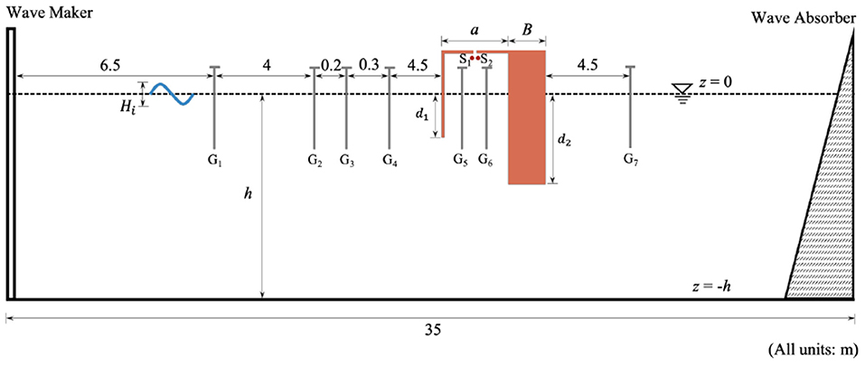
Figure 2. Experiment layout.
2.2. Physical Model and Test Wave Conditions
As sketched in Figure 1, unlike the traditional single OWC device, the proposed device is integrated with a box-like structure, serving as a pile-fixed offshore breakwater. The front plate with a constant small submerged depth is considered, i.e., d1 = 0.04 m, which is beneficial for the wave energy entering the chamber and being absorbed. To model the energy extracting process of the power-takeoff (PTO) system, a long and narrow slot in the middle of the chamber ceiling was made with an opening rate of 1% (divided by the cross-sectional area of the chamber). The air chamber width, a, is fixed at 0.2 m. Besides, B and d2 denotes the width and draft of the rear box, respectively. In experiments, two widths of the rear box (B = 0.1 m and 0.3 m) were tested where the d2 remained 0.2m.
On the basis of Froude similarity criterion, a length scaling of 1:25 was chosen, and the experimental wave conditions and model dimensions tested here are listed in Table 1. The water depth is fixed at 0.5 m, and two incident wave heights are selected (Hi = 0.03 m and 0.05 m). The period of regular incident wave, T, varies from 1 s to 2.4 s with an increment of 0.2 s, and the corresponding wave length, λ, changes from 1.5 m to 5.0 m. The range of dimensionless parameter kh obtained by wave number is 0.6 to 2.1.
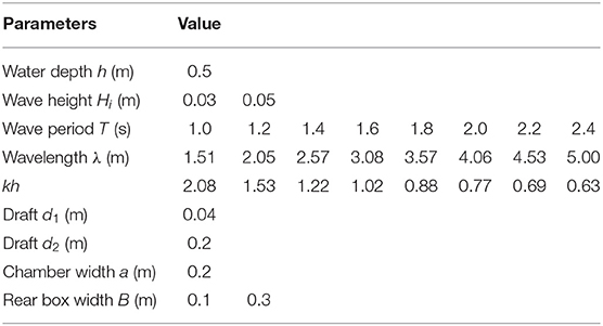
Table 1. Experimental test conditions and model size.
It is worth mentioning that because the scale of the physical model is small, the effect of air compressibility is neglected in this paper (Xu et al., 2016).
2.3. Hydrodynamic Characteristics Calculation
Generally speaking, the time-averaged hydrodynamic energy extracted by the OWC wave energy conversion device over a wave period, EOWC, can be expressed as Equation (1):
where a denotes for chamber width, Pa denotes for the pneumatic pressure, η is the vertical displacement of the water surface inside the chamber, T is the incident wave period, t0 is a reference time instance, and w = 1 for the two-dimensional model.
The incident wave power here is defined as Equation (2):
where ρ is the water density, Ai is the incident wave amplitude, ω denotes the angular velocity, k represents the wave number, and g is the gravity acceleration.
The wave energy conversion efficiency, ξ, is calculated by Equation (3):
By using the two-point method to separate the reflected wave from the time series monitored by wave gauges G2 to G4, the reflection coefficient, Cr, can be computed by Equation (4):
where Hr represents the reflected wave height and Hi represents the incident wave height.
After the wave energy is partially reflected and extracted by the OWC device, the rest transmits underneath the structure and is measured by G7. Similarly, the transmission coefficient, Ct, can be calculated by
where Ht represents the transmitted wave height.
In order to quantify the energy loss due to vortex shedding and fluid separation, the energy dissipation ratio, Cd, is defined by,
3. Numerical Model
3.1. Governing Equations
To complement the experimental scenarios and obtain more detailed flow information, a nonlinear numerical wave tank (NWT) is developed employing the open-source software package OpenFOAM, and the sketch of NWT is plotted in Figure 3. The air inside the chamber is considered as incompressible for small-scale physical model. In order to describe the incompressible two-phase flow motion, the toolbox waves2Foam, programmed based on the interFoam solver, is used to solve the Reynold averaged Navier–Stokes equations, including the continuity (Equation (7)) and momentum conservation equation (Equation (8)). Moreover, the Volume of Fluid (VOF) technique (Hirt and Nichols, 1981) is employed to capture the air–water interface. In Cartesian coordinate system, the basic governing equations are written as follows:
Here, is the velocity vector, ρ is the fluid density, p* is the pseudodynamic pressure, is the acceleration of gravity, is the position vector, μeff is the efficient dynamic viscosity, μ is the dynamic viscosity of water or air, σ is the surface tension coefficient, and κ is the curvature of the interface. It is worth mentioning that k-ω SST buoyancy model (Devolder et al., 2018) is adopted to describe the turbulence phenomenon.
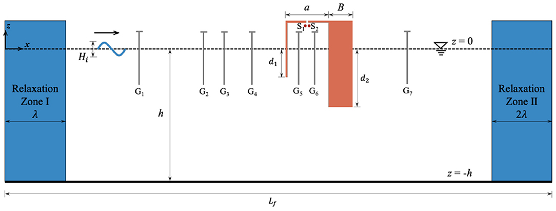
Figure 3. Sketch of numerical wave tank.
For the VOF technique, a single-phase function (α) defined as the proportion of water volume in each cell is introduced, and the phase transport can be described by the following convection equation:
Considering the realistic meaning of phase function, it is essential to apply the MULES (multidimensional universal limiter for explicit solution) (Deshpande et al., 2012) solver to guarantee α being between 0 and 1, where α = 0 denotes gas phase and α = 1 represents liquid phase. Additionally, to ensure clarity of the free surface between gas and liquid phase, numerical dissipation should be minimized as much as possible. Weller (2002) introduced an artificial compression term to keep the interface sharp and the revised format is as follows:
where Ur is the compression velocity between phase water and phase air working only at interface (Rusche, 2003).
Then, ρ and μ are computed by weighted calculation of air and water on the basis of phase function:
3.2. Boundary Conditions
To solve the governing equations uniquely, it is essential to specify the reasonable boundary conditions in the numerical wave tank. OpenFOAM provides many classical boundary conditions, among which the no-slip condition is applied for the rigid structure walls and seabed, and the pressure outlet boundary condition is employed on the atmosphere boundary. As for the wave generation and absorption, the toolbox waves2Foam is utilized to setup the special boundary conditions. The second-order Stokes wave is used in this study to simulate the regular progressive waves. The free surface elevation and velocity components at the inlet boundary can be acquired theoretically as follows:
where η is the free surface elevation, u is the horizontal velocity of water, w is the vertical velocity of water, A is the wave amplitude, ω is the wave angular frequency, k is the wave number, z is the vertical distance from the still water level, and h is the water depth.
In order to eliminate the influences of the reflected/multi-reflected waves, two relaxation zones are deployed at both ends of the NWT. Any physical quantity in the relaxation zones can be calculated by the following equation:
where αR is a weighting factor dependent on the location in the relaxation zone and β is the aimed variable (Jacobsen et al., 2012), which is the weighted combination of the RANS solution in the domain and the theoretical solution based on the boundary definition.
3.3. Numerical Method
The finite volume method (FVM) is used to deal with the governing equations and the computational domain is discretized into a series of non-repeated control volumes, namely cells. Each cell is represented by a node, which locates in the center and the flow field information is stored here.
PIMPLE algorithm is performed to settle the pressure–velocity coupling problem in the incompressible N-S equations, which comprises two algorithms, i.e., Pressure Implicit with Splitting of Operator (PISO) and Semi-Implicit Method for Pressure Linked Equation (SIMPLE), and is mainly inherited from the former algorithm.
As for the numerical discretization schemes in this paper, the Euler scheme is utilized for the time integration, the Gauss limitedLinearV1 scheme for the advective term and the Gauss linear corrected scheme for the Laplacian terms.
4. Verification and Validation
4.1. Numerical Convergence Study
On the basis of FVM, the first step of the numerical model verification is to confirm that the grid setting of the empty wave tank has reached the convergence state, indicating that the calculation has both excellent accuracy and high speed. Five mesh numbers were selected for testing in the range of unit wavelength (Nx) and unit wave height (Nz). It can be concluded that when Nx = 100 and Nz = 12, the wave generated by waves2Foam is capable of maintaining a stable height along the propagation and the calculation cost is relatively low, which is similar to previous studies (Hu et al., 2016). For the time step, referring to the works by Deng et al. (2019), Nt = 1, 000 (discretized number per wave period) is chosen.
In addition, after integrating the OWC model, the flow fields (vortex shedding) near the structure and at the orifice are more complex. Therefore, further refined mesh scheme is needed. To examine the sensitivity of the grid around the structure, three grid discretization schemes including OWC model are considered, i.e., coarse, medium, and fine. The internal water surface elevation and pressure drop are plotted in Figure 4. Despite the slight deviation at the peaks, the overall results under all discrete schemes are quite consistent with each other. Considering both the numerical accuracy and time cost, the medium mesh scheme with the first grid height of 3 mm near the structure boundaries and at least 4 grids at the orifice is chosen.
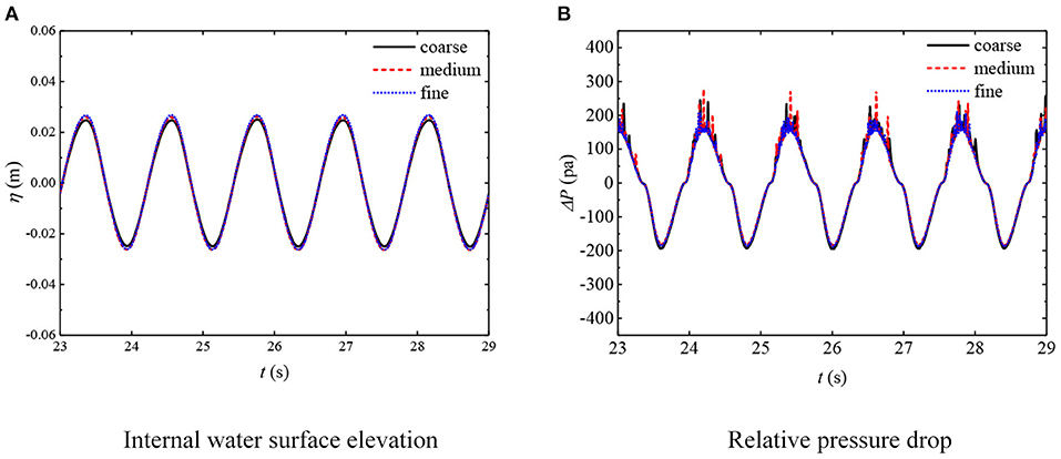
Figure 4. Mesh convergence around the oscillating water column (OWC) device. (A) Internal water surface elevation. (B) Relative pressure drop.
4.2. Comparison Between Experimental and Numerical Results
After the convergency test, the well-validated numerical model is adopted to simulate the interaction between water wave and OWC device. The sketch of the NWT is displayed in Figure 3 and the setup is the same as the experimental one. Moreover, the lengths of relaxation zone I and II are 1.5 and 2 times of incident wavelength, respectively.
The comparison among experiment and numerical simulation for the internal water surface displacement and relative air pressure drop is demonstrated in Figure 5. The results for B = 1.5a, d2 = 0.2 m, Hi = 0.03 m, and T = 2.4 s are considered. In general, except for the discrepancies in the peak and trough, the results for experiment and simulation can meet good consistence. The slight discrepancies may be due to the nonlinear effects caused by the different methods of wave generation between experiments and numerical simulations, since different high-order wave components has different ability entering the inside of water column, which directly affects the hydrodynamic performance at peaks and troughs.
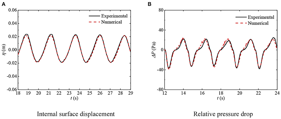
Figure 5. Time series of internal surface displacements and relative pressure drops. In all cases, B = 1.5a, d2 = 0.2 m, Hi = 0.03 m, and T = 2.4 s. (A) Internal surface displacement. (B) Relative pressure drop.
Moreover, the comparisons on the hydrodynamic performance between experiments and numerical simulations, including the wave energy conversion efficiency (ξ), reflection (Cr) and transmission (Ct) coefficients, and energy dissipation coefficient (Cd), are also carried out. The results for one incident wave height (Hi = 0.03 m) together with two box widths (B = 0.5a and 1.5a) are illustrated in Figure 6, where d2 is fixed to 0.2 m. It can be found that ξ, Cr and Ct of the numerical prediction are basically consistent with the experimental ones. As for the energy dissipation coefficient Cd, the experimental results are slightly larger than the numerical ones, which may be attributed to the fact that the selected turbulence closure model in simulations cannot sufficiently duplicate the turbulent processes. Besides, the energy dissipation coefficient is not directly observed, but is approximately calculated by Equation (6) that amplifies the error of reflection and transmission coefficients. Overall, it is proved from the comparisons that the numerical model employed here has high accuracy and credibility in predicting the hydrodynamic properties of the OWC device.
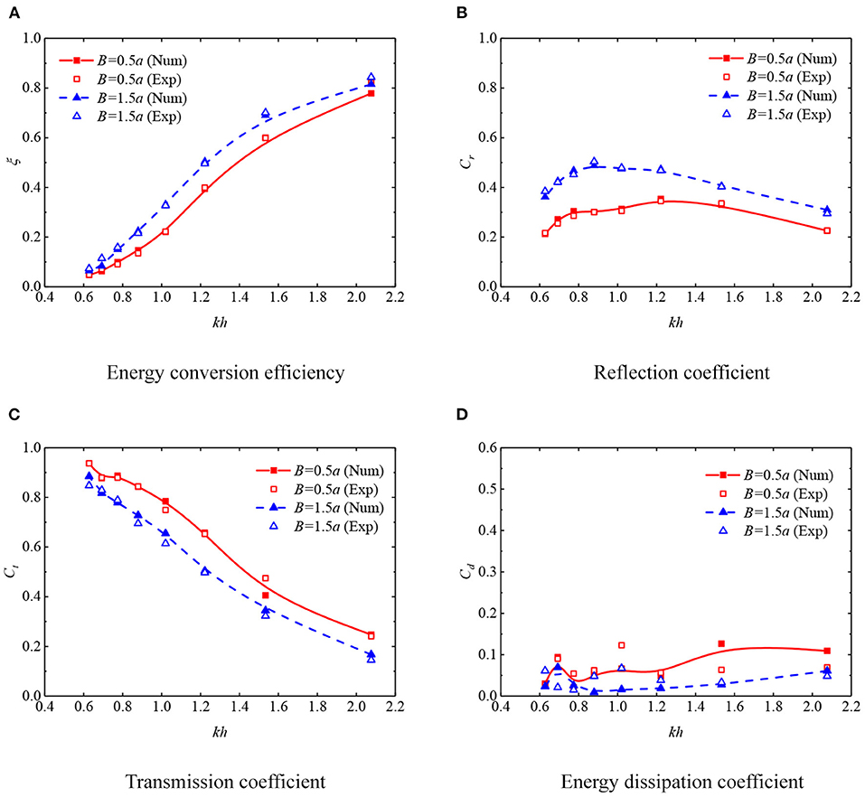
Figure 6. Comparisons of the experimental and numerical results. In all cases, a = 0.2 m, Hi = 0.03 m, and d2 = 0.2 m. (A) Energy conversion efficiency. (B) Reflection coefficient. (C) Transmission coefficient. (D) Energy dissipation coefficient.
5. Results and Discussion
In this section, the numerical simulation of the OWC device mounted on a box-type breakwater, employing the well-validated NWT model, was carried out to explore the hydrodynamic performance, which is affected by the width and draft of the rear box, as well as the incident wave height. For the spatial discretization of the computational domain, the grid discretization strategy described in section 4.1 is adopted. Time step is set as T/1, 000. It is noted that the effects of the draft of front wall and chamber size on the hydrodynamic performance have received much attention in the literature; in this paper, the focus will be mainly paid to the structure configuration of the box.
5.1. Effects of the Width of Rear Box
In this section, the effects of the width of rear box were studied. The draft of rear box is fixed at d2 = 0.2 m, and the incident wave height Hi is 0.05 m. The OWC devices equipped with six rear box widths, ranging from B = 0.05a to 2.5a, were examined in terms of hydrodynamic coefficients ξ, Cr, Ct, and Cd.
Figure 7 indicates that the four hydrodynamic parameters vary against the non-dimensional wave frequency kh for different rear-box widths, and the curves are all fitted based on B-Spline algorithm. Overall, all coefficients are unidirectional with the change of rear box width. As the width of rear box increases, the energy conversion efficiency of OWC device is improved over the full frequency domain considered and the energy dissipation decreases, as shown in Figures 7A,D. Meanwhile, more waves are reflected, especially in the long-wave regimes, and correspondingly less waves transmit across the OWC system, as depicted in Figures 7B,C. It is worth noting that B = 0.05a means the width of rear box is the same as the thickness of front-plate, that is, there is no breakwater platform, while B = 2.5a means the rear box width equaling to the water depth. The maximum of the wave energy conversion efficiency of the former OWC device in Figure 7A is 0.63, while that of the latter one is 0.75, increasing about 19%. If taking ξ = 0.6 as the high-efficient benchmark, the bandwidth of high performance for the OWC device with widest rear box is 1.24 ≤ kh ≤ 2.08, which is as about six times as the one with thinnest box. As for the reflection coefficient Cr in Figure 7B and transmission coefficient Ct in Figure 7C, the maximum increase in Cr and the maximum decrease in Ct of the OWC device equipped with the widest box are 356 and 59%, respectively, compared to the OWC device without the breakwater platform.
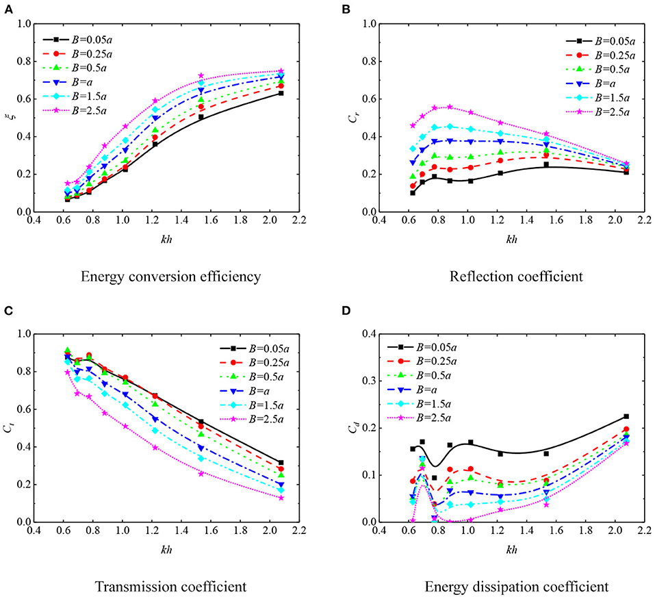
Figure 7. Hydrodynamic coefficients of oscillating water column (OWC) devices with six widths of the rear box under regular waves of Hi = 0.05 m. (A) Energy conversion efficiency. (B) Reflection coefficient. (C) Transmission coefficient. (D) Energy dissipation coefficient.
The energy dissipation coefficient Cd is presented in Figure 7D. When the dimensionless frequency kh is 0.69, there seems to be a peak in the fitting curve. This is the fact that at this frequency, the energy extraction efficiency and reflection coefficient of the wave energy device change very little, but the decrease of transmission coefficient is relatively obvious. Therefore, when calculated according to Equation (6), the dissipation ratio has a small increase. It is worth noting that the ordinate range of the dissipation ratio is 0 to 0.4, not 0 to 1 as in other graphics, so the peak phenomenon is not obvious in value.
The above results show that the OWC device coupled with a relative wider breakwater platform can not only greatly improve the wave-blocking ability but also be beneficial for the wave energy extraction by the OWC device. However, it should be noted that from the engineering application perspective, infinite wide breakwater platform is unrealistic, which should be determined depending on the local engineering requirements. In the present work, the maximum width of B = h (i.e., B = 2.5a) is considered.
5.2. Effects of the Draft of Rear Box
This section attempts to explore the effects of the draft of rear box on the hydrodynamic performance of OWC device. Based on the above investigations, the rear box width of B = 2.5a is chosen, and the incident wave height Hi is still 0.05 m. Four draft schemes were selected, ranging from d2 = d1 to 10d1.
Figure 8 illustrates the variations of hydrodynamic properties against dimensionless coefficient kh. As expected, increasing the immersion depth of the rear box is beneficial for the formation of partial standing waves due to the blocking effect of the rear wall. As a result, the energy conversion efficiency is improved over a wider wave–frequency range. However, if further increasing the draft, namely from d2 = 7.5d1 to 10d1, the efficiency improvement is not obvious, as seen in Figure 8A. Similarly, considering ξ = 0.6 as high efficiency, the highly effective bandwidth for the deepest draft case d2 = 10 d1 is in the range of 1.07 ≤ kh ≤ 2.08, while the bandwidth for d2 = d1 is very narrow, only near kh = 2.08. This is mainly because a larger draft prevents more waves from transmitting to the rear fields beneath the structure, thus being able to be trapped in the chamber and extracted, which is consistent with the trend of transmission coefficient Ct in Figure 8C.
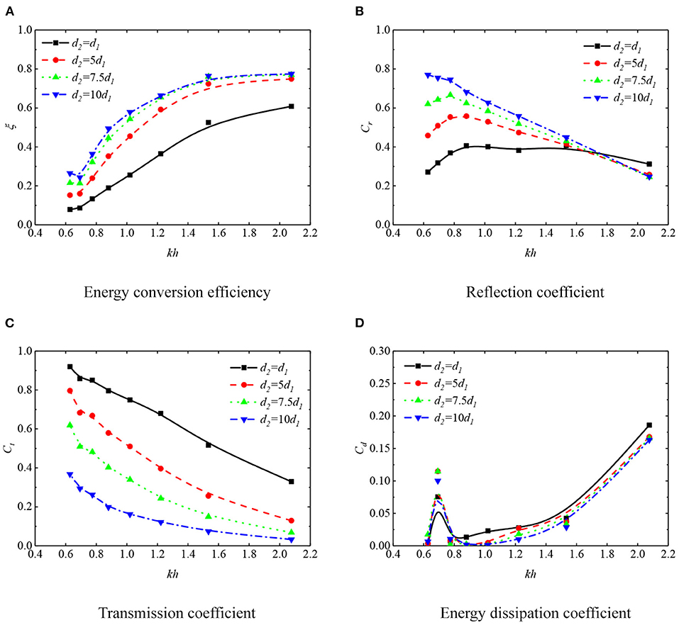
Figure 8. Hydrodynamic coefficients of oscillating water column (OWC) devices with four drafts of the rear box in regular waves of Hi = 0.05 m. (A) Energy conversion efficiency. (B) Reflection coefficient. (C) Transmission coefficient. (D) Energy dissipation coefficient.
Figure 8B plots the fitting curve of the reflection coefficient Cr changing with kh. With the draft of rear box increasing, the long wave is reflected more, but the short wave reflection decreases slightly. Combined with the results of the energy dissipation coefficient Cd in Figure 8D, it may be that the turbulence and nonlinear effect are quite violent at this time, so the energy of short wave is dissipated more. Sincerely, the large submerged depth of rear box can improve the efficiency, but when the draft increases further from d2 = 7.5d1 to 10d1, the energy conversion efficiency increase is not significant, especially in the high wave frequency region. Taking the difficulty and cost of actual engineering construction into account, d2 = 7.5d1 of rear box draft is recommended in this study.
5.3. Effects of the Incident Wave Height
In this subsection, effects of the incident wave height on hydrodynamic performance of the coupling system were examined numerically. The draft of rear box is fixed at d2 = 7.5d1 and the width of rear box is B = 2.5a. The hydrodynamic coefficients of the system under three incident wave heights, i.e., Hi = 0.02 m, 0.03 m and 0.05 m, are considered and the results are plotted in Figure 9.
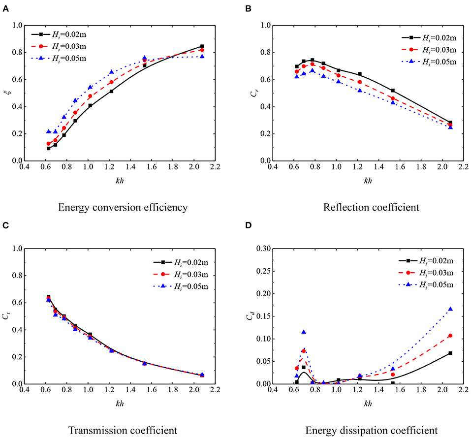
Figure 9. Hydrodynamic coefficients of OWC devices with three incident wave heights for d2 = 7.5d1, B = 2.5a. (A) Energy conversion efficiency. (B) Reflection coefficient. (C) Transmission coefficient. (D) Energy dissipation coefficient.
Figure 9A illustrates the relationship between energy conversion efficiency ξ and non-dimensional parameter kh. There exists a turning point at kh = 1.8. More specifically speaking, for waves whose frequency is less than the turning frequency, steeper waves can enhance the absorption efficiency of the OWC device. However, if larger than this frequency, the efficiency decreases duo to the wave nonlinearity and energy dissipation. Figure 9B shows the effect of wave height on reflection coefficient. It reveals that the steeper the wave height, the less the reflection coefficient over the wave frequency range considered. As expected, the effects of the wave height on the transmission property is neglectable as shown in Figure 9C. The energy dissipation coefficient Cd affected by wave height is shown in Figure 9D. Remarkably, within the high frequency domain (i.e., kh > 1.8), the dissipation of wave energy increases obviously with the increase of incident wave height. This is due to that more wave energy transfers from the fundamental frequency to higher-harmonic components, which increases the turbulent intensity. This also explains that the extracted part of the wave energy is reduced when kh is 2.08, as shown in Figure 9A. However, it should be noted that the low wave energy conversion efficiency does not mean that the total energy extracted from ocean waves is less as well.
5.4. Comparison Between a Breakwater With OWC Device and a Conventional Box-Type Breakwater
To further demonstrate the superiority of the proposed OWC device coupled with a box-type breakwater compared to the conventional box-type breakwater, this section tests the hydrodynamic performances of the OWC device and the traditional breakwater under the same wave conditions. The dimension of the present coupling system is the optimal one, i.e., B = 2.5a, d2 = 7.5d1, and the width of traditional breakwater is equal to the total width of the coupling system, namely B + a. The variations of reflection/transmission coefficients and energy dissipation ratio against kh are shown in Figure 10, respectively.
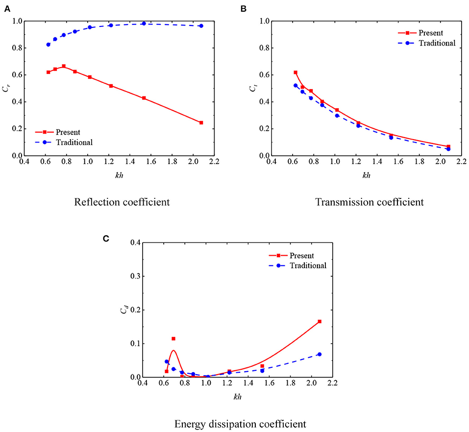
Figure 10. Hydrodynamic coefficients of oscillating water column (OWC) device and traditional breakwater with three incident wave heights for d2 = 7.5d1, B = 2.5a. (A) Reflection coefficient. (B) Transmission coefficient. (C) Energy dissipation coefficient.
Figure 10A shows that the OWC device can significantly reduce the reflection coefficient of the breakwater structure, and the maximum reduction is up to the 75%. Figure 10B indicates that the transmission coefficient of the OWC device rises very slightly. Although part of the solid structure of the traditional box-type breakwater is transformed into an air chamber in present OWC device, it can basically maintain the resistance performance. More importantly, it also weakens the wave reflection greatly in front of the device and provides more stable sea conditions for ship navigation.
The fitting curves using B-Spline algorithm for the energy dissipation ratio of the two breakwaters are plotted in Figure 10C. It can be found that the dissipation coefficient of the present device is larger than that of traditional breakwater at kh = 0.69 and kh = 2.08. As explained in sections 5.1–5.3, the increment of energy loss of present breakwater may be caused by the formation and shedding of vortices in the proximity of the convex corners of structure, as well as the violent turbulence intensity and nonlinear effect.
6. Summary and Conclusions
In this study, the hydrodynamic performance of an integrated OWC-breakwater system is investigated experimentally and numerically. In addition to the geometric dimensions, including the width (B) and draft (d2) of rear box, the influence of incoming wave height (Hi) is examined as well. The hydrodynamic parameters, such as wave energy extraction efficiency (ξ), reflection coefficient (Cr), transmission coefficient (Ct), and energy dissipation coefficient (Cd) are illustrated. Moreover, the superiority of the coupling system, compared to traditional box-type breakwater, is discussed. The following conclusions can be drawn:
1. Compared with the traditional OWC device with thin side wall, the hydrodynamic performance of the OWC device, including wave energy conversion efficiency and wave dissipation performance, can be significantly improved by equipping the rear wall with a box structure of considerable width.
2. The draft of rear box has a profound influence on both the energy contraction and dissipation. Taking the wave energy conversion efficiency and the practical project's cost into full consideration, it is sufficient to adopt the immersion depth of rear box with d2 = 7.5d1.
3. Increasing the incident wave height can improve the wave energy conversion ability except for the short-wave regimes, where more wave energy is dissipated in the front-lip of OWC device due to flow separation and vortex shedding. However, the influence on the wave-blocking ability can be omitted.
4. Compared to the traditional box-type breakwater, the OWC-breakwater coupling system can extract wave energy and simultaneously decrease reflected waves, which is beneficial for ship navigation. In addition, the nearly equivalent wave-blocking performance can be obtained.
Based on the well-validated numerical model of water wave interaction with the OWC device, it is proved that the OWC-breakwater coupling system is beneficial for both wave utilization and navigation safety. However, it should be mentioned that the present system is fixed on water surface. The motion response has significant influence on the hydrodynamic performance, which needs to be investigated in future.
Data Availability Statement
The raw data supporting the conclusions of this article will be made available by the authors, without undue reservation.
Author Contributions
ZD proposed the idea and gave the essential suggestions on manuscript writing. PW performed the numerical simulations, conducted experiment tests, and collected and organized the results. PC conducted the experiment tests and gave valuable discussions of this study. All authors contributed to the article and approved the submitted version.
Funding
We would like to acknowledge the financial support of the National Natural Science Foundation of China (Grants nos. 11802313, 11702244) and the Strategic Priority Research Program of the National Key R&D Program of China (Grants nos. 2018YFC1505500, 2018YFC1505504).
Conflict of Interest
The authors declare that the research was conducted in the absence of any commercial or financial relationships that could be construed as a potential conflict of interest.
Acknowledgments
The authors thank Prof. Haijiang Liu from Zhejiang University for valuable discussions.
References
Ashlin, S. J., Sundar, V., and Sannasiraj, S. A. (2016). Effects of bottom profile of an oscillating water column device on its hydrodynamic characteristics. Renew. Energy 96, 341–353. doi: 10.1016/j.renene.2016.04.091
Count, B. M., and Evans, D. V. (1984). The influence of projecting sidewalls on the hydrodynamic performance of wave-energy devices. J. Fluid Mech. 145, 361–376. doi: 10.1017/S0022112084002962
Deng, Z., Huang, Z., and Law, A. W. K. (2013). Wave power extraction by an axisymmetric oscillating-water-column converter supported by a coaxial tube-sector-shaped structure. Appl. Ocean Res. 42, 114–123. doi: 10.1016/j.apor.2013.05.006
Deng, Z., Huang, Z., and Law, A. W. K. (2014). Wave power extraction from a bottom-mounted oscillating water column converter with a V-shaped channel. Proc. R. Soc. A Math. Phys. Eng. Sci. 470, 20140074. doi: 10.1098/rspa.2014.0074
Deng, Z., Wang, C., Wang, P., Higuera, P., and Wang, R. (2019). Hydrodynamic performance of an offshore-stationary owc device with a horizontal bottom plate: experimental and numerical study. Energy 187:115941. doi: 10.1016/j.energy.2019.115941
Deng, Z., Wang, C., Yao, Y., and Higuera, P. (2020). Numerical simulation of an oscillating water column device installed over a submerged breakwater. J. Marine Sci. Technol. 25, 258–271. doi: 10.1007/s00773-019-00645-0
Deshpande, S. S., Anumolu, L., and Trujillo, M. F. (2012). Evaluating the performance of the two-phase flow solver interFoam. Comput. Sci. Discov. 5:014016. doi: 10.1088/1749-4699/5/1/014016
Devolder, B., Troch, P., and Rauwoens, P. (2018). Performance of a buoyancy-modified k-ω and k-ω SST turbulence model for simulating wave breaking under regular waves using OpenFOAMⓇ. Coast. Eng. 138, 49–65. doi: 10.1016/j.coastaleng.2018.04.011
Evans, D. V. (1976). A theory for wave-power absorption by oscillating bodies. J. Fluid Mech. 77, 1–25. doi: 10.1017/S0022112076001109
Evans, D. V. (1982). Wave-power absorption by systems of oscillating surface pressure distributions. J. Fluid Mech. 114, 481–499. doi: 10.1017/S0022112082000263
Falcão, A. F. d. O. (2010). Wave energy utilization: a review of the technologies. Renew. Sustain. Energy Rev. 14, 899–918. doi: 10.1016/j.rser.2009.11.003
Goda, Y., and Suzuki, Y. (1976). Estimation of incident and reflected waves in random wave experiments. Coast. Eng. Proc. 1, 47. doi: 10.9753/icce.v15.47
He, F., Huang, Z., and Law, A. W. K. (2013). An experimental study of a floating breakwater with asymmetric pneumatic chambers for wave energy extraction. Appl. Energy 106, 222–231. doi: 10.1016/j.apenergy.2013.01.013
Heath, T. V. (2012). A review of oscillating water columns. Philos. Trans. R. Soc. A Math. Phys. Eng. Sci. 370, 235–245. doi: 10.1098/rsta.2011.0164
Hirt, C. W., and Nichols, B. D. (1981). Volume of fluid (VOF) method for the dynamics of free boundaries. J. Comput. Phys. 39, 201–225. doi: 10.1016/0021-9991(81)90145-5
Howe, D., and Nader, J. R. (2017). OWC WEC integrated within a breakwater versus isolated: Experimental and numerical theoretical study. Int. J. Mar. Energy 20, 165–182. doi: 10.1016/j.ijome.2017.07.008
Hu, Z., Greaves, D., and Raby, A. (2016). Numerical wave tank study of extreme waves and wave-structure interaction using OpenFOAM. Ocean Eng. 126:329–342. doi: 10.1016/j.oceaneng.2016.09.017
Jacobsen, N. G., Fuhrman, D. R., and Fredsøe, J. (2012). A wave generation toolbox for the open-source CFD library: OpenFOAM. Int. J. Numer. Methods Fluids 70, 1073–1088. doi: 10.1002/fld.2726
Lovas, S., Mei, C. C., and Liu, Y. (2010). Oscillating water column at a coastal corner for wave power extraction. Appl. Ocean Res. 32, 267–283. doi: 10.1016/j.apor.2010.06.004
Martins-Rivas, H., and Mei, C. C. (2009a). Wave power extraction from an oscillating water column along a straight coast. Ocean Eng. 36, 426–433. doi: 10.1016/j.oceaneng.2009.01.009
Martins-Rivas, H., and Mei, C. C. (2009b). Wave power extraction from an oscillating water column at the tip of a breakwater. J. Fluid Mech. 626, 395–414. doi: 10.1017/S0022112009005990
Mustapa, M. A., Yaakob, O. B., Ahmed, Y. M., Rheem, C. K., Koh, K. K., and Adnan, F. A. (2017). Wave energy device and breakwater integration: A review. Renew. Sustain. Energy Rev. 77, 43–58. doi: 10.1016/j.rser.2017.03.110
Ning, D., Guo, B., Wang, R., Vyzikas, T., and Greaves, D. (2020a). Geometrical investigation of a U-shaped oscillating water column wave energy device. Appl. Ocean Res. 97:102105. doi: 10.1016/j.apor.2020.102105
Ning, D., Ke, S., Mayon, R., and Zhang, C. (2019). Numerical investigation on hydrodynamic performance of an OWC wave energy device in the stepped bottom. Front. Energy Res. 7:152. doi: 10.3389/fenrg.2019.00152
Ning, D., Zhou, Y., Mayon, R., and Johanning, L. (2020b). Experimental investigation on the hydrodynamic performance of a cylindrical dual-chamber oscillating water column device. Appl. Energy 260:114252. doi: 10.1016/j.apenergy.2019.114252
Qiu, S., Liu, K., Wang, D., Ye, J., and Liang, F. (2019). A comprehensive review of ocean wave energy research and development in China. Renew. Sustain. Energy Rev. 113:109271. doi: 10.1016/j.rser.2019.109271
Rusche, H. (2003). Computational Fluid Dynamics of Dispersed Two-phase Flows at High Phase Fractions. Ph.D. thesis, Imperial College London (University of London).
Vyzikas, T., Deshoulières, S., Barton, M., Giroux, O., Greaves, D., and Simmonds, D. (2017). Experimental investigation of different geometries of fixed oscillating water column devices. Renew. Energy 104, 248–258. doi: 10.1016/j.renene.2016.11.061
Weller, H. (2002). Derivation, Modelling and Solution of the Conditionally Averaged Two-phase Flow Equations. Nabla Ltd., No Technical Report TR/HGW 2.
Xu, C., Huang, Z., and Deng, Z. (2016). Experimental and theoretical study of a cylindrical oscillating water column device with a quadratic power take-off model. Appl. Ocean Res. 57, 19–29. doi: 10.1016/j.apor.2016.02.003
You, Y., Li, W., Liu, W., Li, X., and Wu, F. (2010). Development status and perspective of marine energy conversion systems. Autom. Electr. Power Syst. 34, 1–12.
Zhao, X., Ning, D., Zou, Q., Qiao, D., and Cai, S. (2019). Hybrid floating breakwater-wec system: a review. Ocean Eng. 186, 106126–106126. doi: 10.1016/j.oceaneng.2019.106126
Zheng, S., Zhang, Y., and Iglesias, G. (2019). Coast/breakwater-integrated OWC: a theoretical model. Mar. Struct. 66, 121–135. doi: 10.1016/j.marstruc.2019.04.001
Keywords: wave energy conversion, oscillating water column, hydrodynamics, experimental and numerical study, energy dissipation
Citation: Deng Z, Wang P and Cheng P (2021) Hydrodynamic Performance of an Asymmetry OWC Device Mounted on a Box-Type Breakwater. Front. Mar. Sci. 8:677030. doi: 10.3389/fmars.2021.677030
Received: 07 March 2021; Accepted: 26 April 2021;
Published: 22 June 2021.
Edited by:
Dezhi Ning, Dalian University of Technology, ChinaReviewed by:
Wang Chen, Tsinghua University, ChinaHongda Shi, Ocean University of China, China
Yongliang Zhang, Tsinghua University, China
Copyright © 2021 Deng, Wang and Cheng. This is an open-access article distributed under the terms of the Creative Commons Attribution License (CC BY). The use, distribution or reproduction in other forums is permitted, provided the original author(s) and the copyright owner(s) are credited and that the original publication in this journal is cited, in accordance with accepted academic practice. No use, distribution or reproduction is permitted which does not comply with these terms.
*Correspondence: Pengda Cheng, cGRjaGVuZ0BpbWVjaC5hYy5jbg==