 Shinsuke Kawagucci
 Yohei Matsui
 Hidetaka Nomaki
 Chong Chen
- 1Super-cutting-edge Grand and Advanced Research (SUGAR) Program, Institute for Extra-cutting-edge Science and Technology Avant-garde Research (X-star), Japan Agency for Marine-Earth Science and Technology (JAMSTEC), Yokosuka, Kanagawa Prefecture, Japan
- 2Marine Biodiversity and Environmental Assessment Research Center (BioEnv), Research Institute for Global Change (RIGC), Japan Agency for Marine-Earth Science and Technology (JAMSTEC), Yokosuka, Kanagawa Prefecture, Japan
Recovery of samples from the deep ocean in pristine condition is difficult due to large environmental differences between the deep and surface waters through which the samples necessarily must be transported. Here, we propose a concept for deep-sea sample recovery: a deep-sea freezer using thermoelectric cooling capable of generating ice in the deep and recover them frozen on-board ships. As a proof of concept, we present the DSF-α, a prototype Deep-Sea Freezer based on Peltier device rated at 2000 m. In situ assessments of the DSF-α on remotely operated vehicles showed its capacity to reach freezing (-13.0°C) temperatures in the deep, as well as recovering seawater frozen on deck. Although the DSF-α is limited in that achieving sufficient freezing for useful sample recovery is time consuming, the deep-sea freezer opens a whole frontier of new possibilities for preserving various types of deep-sea samples and has the potential to be adapted according to various needs of the deep-sea research community. With the first literal ‘marine snow’ in the deep, we offer a glimpse to a future where the recovery of reliable bathyal samples is no longer laborious.
Introduction
The deep sea is a dark, cold realm making up to 95% of the ocean (Drazen and Sutton, 2017). It is home to unique ecosystems such as hydrothermal vents and is now known to play critical roles in maintaining the Earth’s functions on which our society depends, such as carbon dioxide capture and storage (Armstrong et al., 2012). We are far from understanding how ecosystems function in situ in the deep (Folkersen et al., 2019), hindered partly by the difficulty in recovering pristine samples. Environmental conditions such as temperature and pressure at the deep-sea bottom are very different from the surface water above. Recovering samples from the deep sea inevitably means transporting them through this difference, risking alterations from the original in situ state (La Cono et al., 2015). Maintaining samples as close to the original condition as possible is at the heart of deep-sea science, particularly deep-sea biology and geochemistry, with new techniques constantly being developed and used.
Freezing is the most effective, efficient, and widely used sample preservation method in natural sciences, capable of inhibiting almost all sources of sample condition alterations. This includes not only changes in metabolism and gene expression but also evaporation, oxidation, and breaking down of organic components, making it ubiquitously useful for all sample types. However, although cold, the deep sea has never been frozen, even during the “Snowball Earth” glaciation periods (Ashkenazy et al., 2013). Normally, freezing samples during field work requires transportation of commercial (deep) freezers and/or coolants such as liquid nitrogen or dry ice. However, commercial freezers using the vapour-compression refrigeration are unviable underwater – taking coolants to the deep sea is not realistic as this requires large, specialised pressure containers. To our knowledge, no example of freezing seawater or samples in situ in the deep sea has been published although gases stripped from shallow water (<200 m depth) have been frozen inside the housing of a device based on Stirling-type cooler (Gentz and Schlueter, 2012).
We propose a concept to realise deep-sea freezing, using thermoelectric cooling with small-sized, light-weight Peltier coolers. These plate-like semiconductor devices convert electric power to temperature differences between the two faces, by the Peltier effect (Peltier, 1834). When DC current is applied, heat absorption occurs on one side of the Peltier device and a temperature difference is generated from the other side. In principle, maintaining the ‘hot’ side of a Peltier cooler capable of generating 60°C of temperature differences at 5°C means the ‘cool’ side is at -55°C, resulting in the freezing of seawater. Previously, a thermoelectric cooling module was designed and tested for use in the deep sea (Kyo and Itoh, 1994), but this device was only capable of cooling the seawater to ~3°C and was not viable as a freezer. A temperature-preserving deep-sea water sampler based on thermoelectric cooling was recently developed (Wu et al., 2022), but this only intended to preserve the in situ temperature and not used as a deep-sea freezer. Though there were certainly other attempts to build deep-sea coolers based on the same concept, they remained unpublished to our knowledge.
Here, we report the successful construction of the first prototype deep-sea freezer, named DSF-α (Deep-Sea Freezer version α), opening new possibilities for deep-sea sample recovery. The DSF-α was tested in situ first on December 25th, 2020 on the Remotely Operated Vehicle (ROV) Hyper-Dolphin on-board R/V Shinsei-Maru cruise KS-20-J07, where the formation of first deep-sea ice was confirmed by video camera being available for monitoring. On February 3rd, 2021 we successfully recovered the deep-sea ice from 850 m depth with DSF-α powered by the ROV KM-ROV during the R/V Kaimei cruise KM21-E02 despite no video camera being available for monitoring. Although some time was required for the freezing process, our laboratory-based and in situ dive tests provides the first proof of concept that deep-sea freezing by a Peltier cooler is possible.
Materials and procedures
Materials
The prototype DSF-α (Figure 1) consists of a Peltier device (PD; Figure 1, No. 2), two copper blocks attached to the ‘hot’ (exothermic) and ‘cool’ (endothermic) faces of the PD, an aluminium-made heat sink chamber, a thermocouple, an electric connector, a pressure housing, an electric unit housing, and a peristaltic pump. We used a commercially available PD (UT7070-AL, SCNT Inc., Japan), deemed suitable due to its capacity to achieve endothermic transfer rate as high as 132 W or generate temperature differences between faces up to 72K with dimension of 73 x 72 x 5 mm (width x depth x height). The faces are made of aluminium for high conductivity on the surface. The maximum heat transfer rate of 132 W is achieved at power supply of DC28V and 7A (196 W), demonstrating that 64 W is used to drive the PD and exhausted from the ‘hot’ surface as well as the transferred heat. The two copper blocks (Figure 1, No. 3, 7) are mounted on two sides of the PD, one on the ‘hot’ and one on the ‘cool’ side. One side of the exothermic copper block has a smooth surface in order to achieve a perfect fit on the PD, while the other surface has a series of fins (Figure 1, between No. 7 and 8) to increase the efficiency in heat transfer. The endothermic copper block has a similar smooth surface for firm attachment to the PD while the other side is convex, or the copper block was modified into an opening for mounting different types of copper attachment (details below). Areas of and thickness of the endothermic and exothermic copper block surface mounted onto the PD are 20 cm2, 2.0×10⁻³ m2, 56 mm, and 21.5 mm, respectively. Small gaps between each block and the surface of the PD are filled with grease (TK-P3D, Sanwa-Supply Inc., Japan) to achieve a tight fit for efficient heat conduction. The heat sink (Figure 1, No. 6-8) consists of an exothermic copper block core, further bound to a series of aluminium blocks (for pressure resistance, see below). To ensure the two copper blocks tightly sandwich the PD for effective heat transfer, a series of spring structures is installed around them. Two stainless-steel tubes (SS-4BHT-6, Swagelok, US) penetrate into the pressure housing, one for supplying ambient seawater for cooling and one for discharging after use (Figures 1B-D, No. 15). To radiate the heat from the exothermic copper block, cool ambient seawater is drawn in by an external peristaltic pump (Figure 1A) through the water path into a space where the heat-radiating copper fins are positioned among the heat sink (Figure 1C). A thermocouple inserted in the gap between the cooling surface of the PD and the endothermic copper block serves to confirm operation of the PD by monitoring the temperature. An electric connector (HYDRO, U.K.) for power supply (DC24V, Max 8A) and communicating temperature data serves to connect the main body of DSF-α via the electric unit of DSF-α to the electric ports of the ROV.
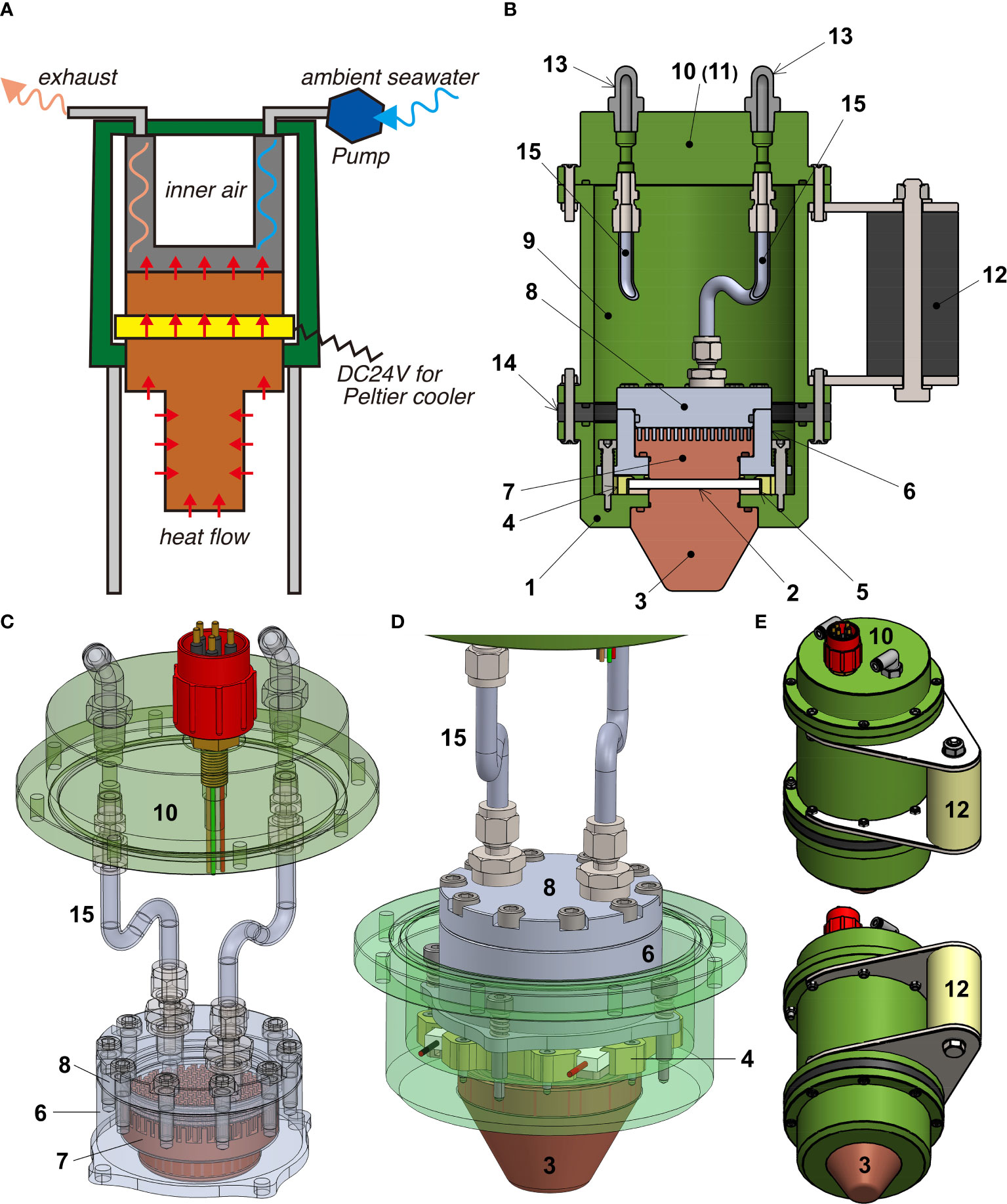
Figure 1 Schematics and illustrations of the DSF-α. (A) Block diagram showing the concept. (B) Internal construction of the whole system. (C) Perspective illustration of the heat sink. (D) Perspective illustration of the Peltier device (PD) and the surrounding heat transfer mechanism. (E) Overview of the system’s exterior. Numbers correspond to: 1, Base of the PD and the lower end of the pressure housing; 2, Thermoelectric PD; 3, Endothermic ‘cooling’ copper block; 4, Horizontal holder for the PD made by synthetic resin; 5, Insulation layer between PD and the pressure housing made by synthetic resin; 6, Lower part of the aluminium block surrounding the holding exothermic copper block to facilitate heat transfer; 7, Exothermic ‘hot’ copper block; 8, Upper part of the heat sink aluminium block connected to the water inlet and exhaust; 9, Wall of the pressure housing; 10, Top of the pressure housing with inhalant/exhalent tubes for the cooling water and containing the electric communication connector (11); 12, Handle for manipulation by the submersible; 13, Connectors for cooling water inlet and the peristaltic pump; 14, O-shaped insulation layer; 15, Stainless-steel flexible tubes used to transport cooling water.
The pressure housing of the DSF-α is constructed from TUFRAM-coating aluminium and is designed to resist a pressure of 20 MPa, corresponding to 2,000 m water depth, with a safety coefficient of 3. Pressure tolerance at 20 MPa was confirmed by a pressure test conducted in a pressure chamber in Japan Agency for Marine-Earth Science and Technology (JAMSTEC), Japan. The casing on the exterior is a 2000 m rated pressure housing comprising of three parts, (1) the tube-like main housing, (2) the ‘cool’ or endothermic copper block on one end, and (3) an ‘end cap’ where the inhalant and exhalant tubes pass through on the other end (Figure 1C).
The secondary mechanism for pressure resistance of the PD, especially against high pressure of seawater that is penetrated for cooling, is the heat sink chamber. As ambient seawater is taken into the heat sink chamber for cooling, both inhalant and exhalent tubes are under high pressure, same with the heat sink chamber. The heat sink chamber consists of two aluminium blocks with the exothermic copper block. One aluminium block (Figure 1, No. 6) is a tube-like structure that surrounds the exothermic copper block. The copper block is T-shaped in cross section, which binds to the aluminium block which is L-shaped in cross section (Figures 1B, D). The second aluminium block (Figure 1, No. 8) is married to the fins of the exothermic copper block. The two aluminium blocks are joined by 10 hexagon coupling bolts (Figure 1C), the tightening of these bolts contributes to pressure tolerance. The inner space, including the PD, of the pressure housing is kept under atmospheric pressure even in the deep sea, owing to pressure resistance exhibited by tight connections between the endothermic copper and the pressure housing (1 and 3, Figure 1B), as well as the aluminium block and stainless-steel tubing (6-8 and 15, Figure 1C) in which ambient seawater passes for cooling.
The main system of the DSF-α has a diameter of 150 mm and is 263 mm in height, not including projections from the electric connector. Weight of the main system is 9.5 kg in air and 5.5 kg in water. The peristaltic pump is powered directly from the ROV, and is independent from the main electric system of the DSF-α. An acrylic resin cubic housing was used to contain the DSF-α system during both laboratory-based and in situ deep-sea examinations. During laboratory-based examinations, a closed-loop water chiller was used to continuously supply cooled water to the heat sink for cooling, in place of the peristaltic pump and ambient seawater used in situ. For the first in situ deep-sea examination, copper mesh was fitted onto the endothermic copper block, surrounding it like a tube, to increase the visibility of ice on the cameras when generated. For the second in situ deep-sea assessment and the further laboratory experiments that followed, an optional spear-like attachment on the endothermic (cool) copper block covered by acrylic tubing similar to conventional push corers was used (Figure 2A). We also designed another optional attachment with a copper disk for efficient sampling of microbial mats (Figure 2B), but this was not applied in this study.
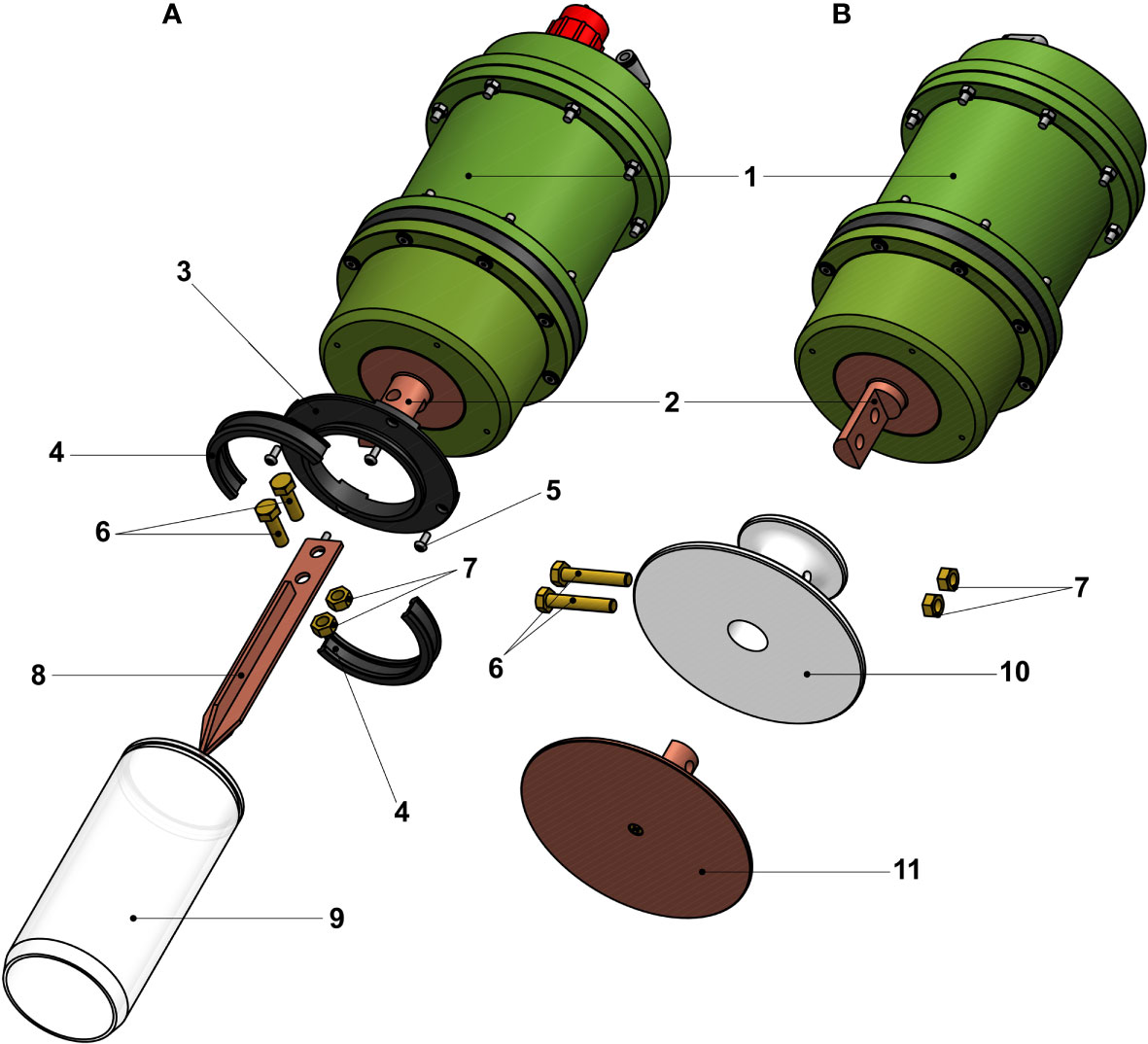
Figure 2 Schematics and illustrations of optional copper attachments for the endothermic copper block the DSF-α. (A) Spear-like attachment with acrylic tube similar to conventional push corers. (B) Disk-like attachment for the collection of microbial mats. Numbers correspond to: 1, Pressure housing of the DSF-α; 2, Endothermic ‘cold’ copper block with holes for attaching the optional parts; 3, Base of the acrylic tube; 4, end cap of the acrylic tube; 5, Screws for the base; 6, Screws to secure the attachment on to the endothermic copper block; 7, M8 nuts for the screws (6); 8, Spear-like copper block; 9, Acrylic tube (ϕ120mm and L180 mm); 10, Insulation for the disk-like copper block; 11, Disk-like copper block.
Procedures
During the assessments, the water chiller (for lab-based tests) or the peristaltic pump (for the in situ test) was powered on first, before the main DSF-α system, to avoid the main system being heated prior to starting up. After several minutes, electric power was supplied to the DSF-α to initiate the operation of the PD, as well as the temperature monitoring.
Assessment
Test 1: laboratory-based examination in air
A typical pattern of temperature changes and the progress of ice generation with the DSF-α tested exposed to air at atmospheric pressure without insulation during laboratory-based examination is shown in Figure 3A. Initial temperatures of fresh water in the acrylic chamber and chiller was set at +5°C, while the room temperature was 20°C. Temperature monitored by the thermocouple on the cold surface of the PD in the DSF-α was 12°C when the power supply to the main system started. The temperature of the DSF-α decreased to 5°C after 1 minute, further decreasing thereafter to 0°C after 4 minutes and -5°C after 12 minutes. At that time, thin layer of ice covering the endothermic, convex, copper block was visible. Water exhaled from the DSF-α after cooling the system was always below 7°C; the maximum temperature difference between the exhalent water and the DSF-α‘s cool side was 18°C. The DSF-α system was operated continuously for 3 hours, after which the temperature had decreased down to -12°C and the layer of ice, clear and colourless in appearance, had grown up to approximately 20 mm in thickness. The electric current supplying the PD (DC24V) was almost stable at 6.0 A during the experiment. The whole pressure housing body of the DSF-α was also cold, suggesting sufficient heat removal by the heat sink mechanism while conductively cooling the metal body by the PD. We also repeated the same experiment while wrapping the whole DSF-α system in a layer of cloth-based insulation from air, and in that case the inhalant and exhalant water stayed at 3°C and 6°C, respectively, but the DSF-α temperature dropped to as low as -20°C (data not shown). This was deemed to be the lowest temperature achievable with the DSF-α.
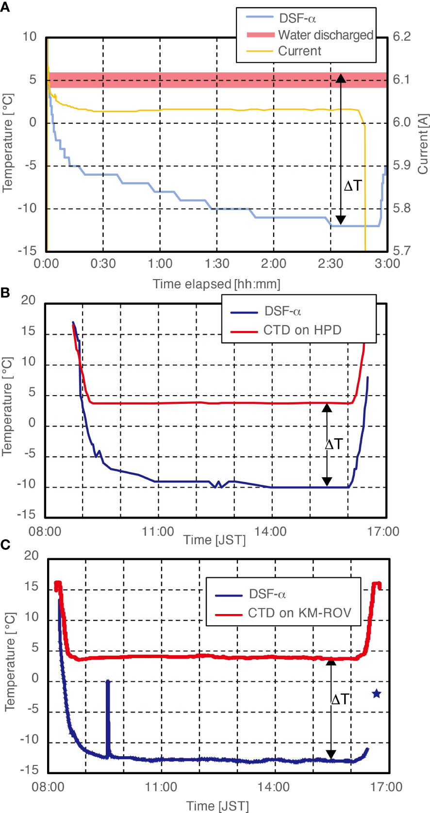
Figure 3 Temperature recorded during Assessment Tests 1 and 2 of the DSF-α. (A) Laboratory-based assessment (without additional insulation layer in air). (B) In situ field assessment on the ROV Hyper-Dolphin (HPD) without additional insulation layer. (C) In situ field assessment on the KM-ROV using an additional insulation layer. The peak between 09:00 and 10:00 represents a short period when we had to turn temperature recordings during a troubleshooting session by the ROV team. ΔT represents the temperature difference made by the DSF-α.
These laboratory experiments served as a benchmark for the cooling capability of the DSF-α and suggested possible limiting factors. The exhaled water was at a constant temperature throughout the laboratory-based operation of the DSF-α, indicating that steady state was reached for heat transfer to the heat sink. A general equation representing thermal conductivity (as follows) and physical properties of the exothermic copper block at the steady state gives the estimated temperature of the PD’s hot side:
Where
Q: heat transfer rate ([W], unknown)
A: Area of copper block touching the PD ([m2], 2.0×10⁻³)
L: Thickness of the copper block, excluding the fins ([m], 21.5×10⁻³)
λ: Material-specific thermal conductivity ([W K-1 m-1], 400 for pure copper)
Th: Temperature at the hot side of the copper block ([K], unknown)
Tc: Temperature at the cool side of the copper block ([K], 279 = +6°C exhaled water)
We can determine that the heat transfer rate at the heat sink was at 126 W, from the observed water flow rate of 10 mL sec-1 and the observed temperature difference between the inhaled/exhaled water of 3K. Substituting Q with 126 W, the equation generates a Th of 282K (9°C). Although limitations in the accuracy, precision, and resolution in our quantification of the flow rate and water temperatures could have resulted in some deviations in the estimated heat transfer rate and the output Th value, this level of uncertainty is deemed to be not vital for the overall evaluation of the system’s capability.
The Th (i.e. temperature of exothermic surface of the PD) of 282K and the endothermic surface of the PD reaching only -20°C during the experiment indicate that the PD of DSF-α was generating a 29K temperature difference despite its catalogue specifications noting a capacity to generate a 72K difference. The PD-specific heat transfer rate at the temperature difference of 29K with power supply of DC24V and 5.8A is expected to be 70 W (catalogue spec.). This supports our estimated heat transfer rate of 126 W, as it is approximately equivalent to the sum of the estimated endothermic rate (70 W) and heat loss for operating the PD (<64 W, see Materials).
Conversely, if we assume that the PD was indeed generating its maximum temperature difference of 72K as listed on its catalogue specifications, the Th should be 52°C (325K) as the lowest temperature observed at the DSF-α thermocouple was -20°C. Substituting a constant Th value of 325K into Eq1 results in a heat transfer rate of 1712 W. This estimation is an order of magnitude greater than the abovementioned estimation (126 W) from the observed temperatures and flow rate of the inhalant/exhalent cooling water. As such, the PD was unlikely to be operating at its catalogue temperature difference in the DSF-α. Therefore, the limiting factor of the cooling capability (and therefore the lowest temperature observed on the endothermic side) seen in the DSF-α during the three hours of operation is probably due to the system reaching its maximum heat transfer capacity, rather than the maximum temperature difference (i.e. 72K) being reached.
We deduce that, due to the continuous transfer of heat energy from the air through the metallic pressure housing, the maximum heat transfer rate of the DSF-α system was insufficient for the system to reach 72K of temperature difference. This is also supported by the temperature at the cool side of the PD being lowered when the system was insulated from the air. Similar phenomenon can be expected when operating the system under water, placing limitation on the temperature that can be realistically reached at the endothermic side with the DSF-α.
Test 2: in situ deep-sea assessment
The DSF-α system, mounted on the acrylic chamber without insulation, was secured on the front side of payload basket on the ROV Hyper-Dolphin (Figures 4A, B). Dive #2120 of ROV Hyper-Dolphin was conducted off Hatsushima Island (35°01.0’N 139°13.3’E), Sagami Bay on December 25th, 2020 during the R/V Shinsei-Maru cruise KS-20-07J. A video camera was set to continually monitor and record the ice formation in the DSF-α chamber. When the ROV was deployed at the sea surface (08:22 JST, same for all time stamps hereafter), air in the heat sink space of the DSF-α was substituted by surface seawater which was at 20°C.
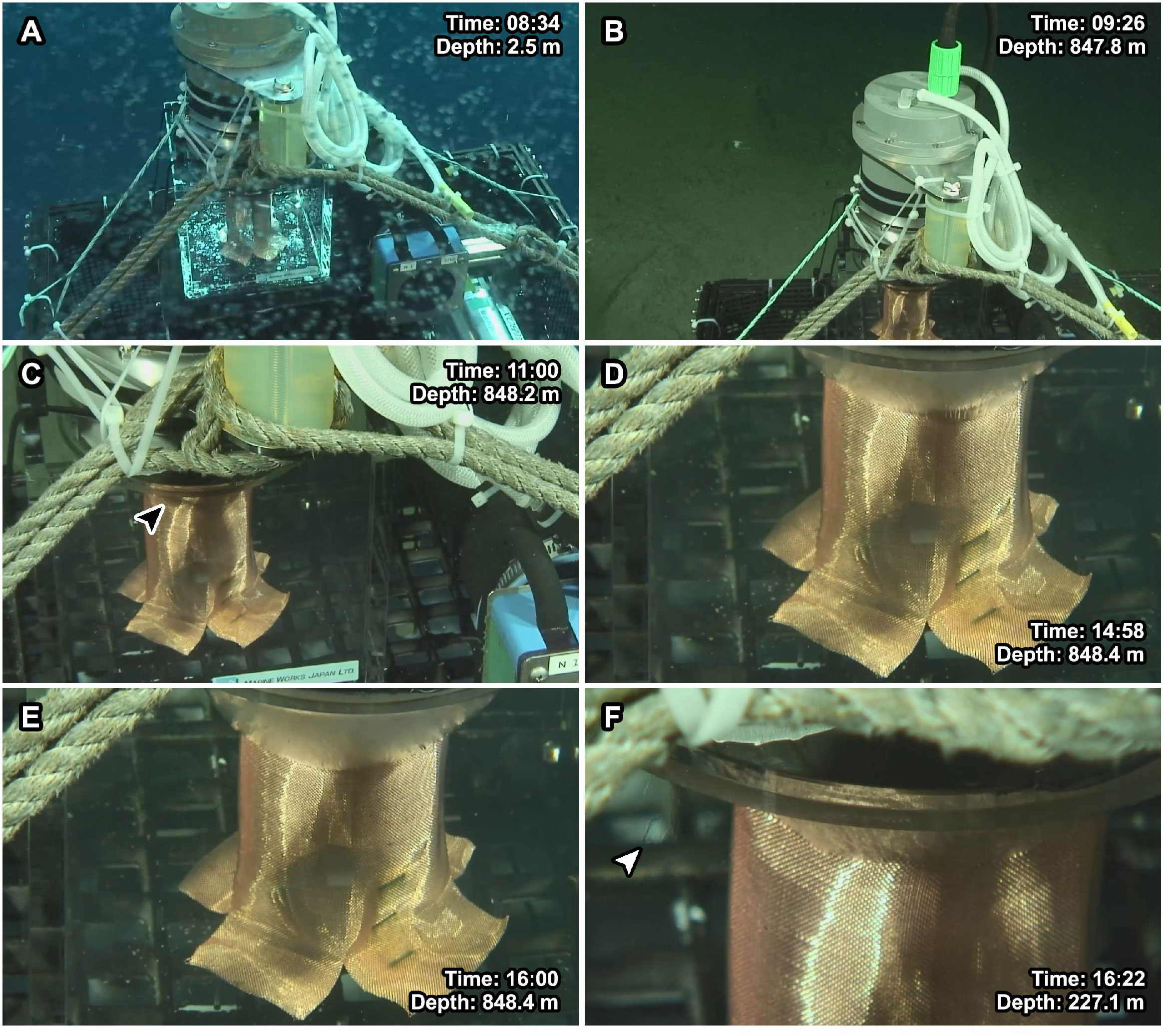
Figure 4 Observations of the DSF-α during the field assessment on-board ROV Hyper-Dolphin on the Christmas Day of 2020 (Figure 3B). (A) Right after deployment showing the overview of the system. (B) Arrival at seafloor. (C) The first visible ice crystals (filled arrow pointing to the ice). (D) Deep-sea ice growing in size. (E) The maximum amount of ice generated during this dive. (F) The melting ice generates shimmering water (open arrow), the ice’s size decreases.
The peristaltic pump was started when the ROV arrived at the sea surface, and following that the power supply to the PD was started at 08:52, at the water depth of 300 m. At this point the ambient temperature was 11.1°C while the ‘cool’ face of the DSF-α was at 14°C. At 600 m (09:04) depth the DSF-α temperature measurement decreased to 0°C, where ambient seawater temperature was 5.4°C (Figure 3B). The lack of shimmering waters at the exhaust vent of the peristaltic pump suggests the seawater that has passed through the heat sink chamber was not significantly warmer than the ambient seawater. At 09:19, just after the ROV arrived at the seafloor (depth 854 m, ambient seawater temperature 3.7°C), the temperature of the DSF-α has decreased to -5°C. Production of the first deep-sea ice was initially seen near the opening of the housing chamber at around 11:00 (Figure 4C; Supplementary Video 1), when the DSF-α temperature had reached -9°C. The lowest temperature of the ‘cool’ side of the DSF-α system recorded during the dive was -10°C which was maintained for 3.5 hours (Figure 4D). The deep-sea ice steadily increased in size until 16:00 (Figure 4E), when the ROV left the sea bottom for recovery. The deep-sea ice had a cloudy, slurry appearance which suggests it is slush-like rather than a solid block. During the ROV’s ascent, the temperature of the ‘cool’ face on the DSF-α increased with time (due to shallower depth and increasing ambient seawater temperature). While ascending, seawater around the deep-sea ice exhibited a shimmering appearance (Figure 4F). This suggested that the ice was starting to melt, generating a water density difference between the surrounding seawater and water originating from the melting deep-sea ice. Melting was more rapid past the water depth of 600 m, where the ambient seawater temperature was 5°C. The deep-sea ice continued to reduce in size and was visible until the depth of 100 m at 16:25 when the DSF-α was turned off. The shimmering effect disappeared at 16:28, when the ROV reached the sea surface. The deep-sea ice had completely melted when the DSF-α was observed after the ROV recovered on-deck.
Since we know from laboratory-based assessments that the main limitation of the DSF-α is the heat transfer from the outside world to the metal housing, we tested the system again after adding a layer of insulation outside the pressure housing (Figure 3C). The DSF-α was equipped with cloth-based insulation and a point-ended, spear-like copper attachment was mounted as an extension of the exothermic copper block, in turn covered by an acrylic tube similar to a conventional push corer (Figure 2A). The device was mounted on the rear payload rack of KM-ROV during dive #150, on-board the R/V Kaimei cruise KM21-E02. This dive was also undertaken off Hatsushima Island in Sagami Bay, on February 3rd, 2021. Unfortunately, no video camera was available for constant monitoring of the ice formation process during this dive. The test procedure was similar to that during the ROV Hyper-Dolphin Dive #2120, except the extra layer of insulation. Water temperature was 16°C on the sea surface when the ROV was deployed (08:17), steadily decreasing until arrival at the sea bottom at 998 m deep (08:49) after which it stabilised around 4°C (Figure 3C). Temperature of the endothermic side of the PD on the DSF-α reached -13.0°C just before 10:00, a steady state which it maintained relatively constantly until the ROV left bottom at 16:07. The temperature difference of 17°C generated during this dive is 3°C greater than the assessment without the insulation layer, showing that better insulation indeed would increase the efficiency of deep-sea freezers. The DSF-α was shut down during ROV ascending around 300 m at 16:31, when the DSF-α and ambient seawater were at -11.1°C and 11°C, respectively. At 16:41, when the ROV reached at 30 m, the DSF-α and ambient seawater were at approximately -2°C and 16.9°C, respectively. Ice generated by the DSF-α was successfully retained during the ROV’s recovery process (approximately 200 mL of ice at the base of the spear-like attachment) and we successfully recovered deep-sea ice on-board R/V Kaimei. Ion chromatographic analysis of the water obtained from melting the ice generated by the DSF-α revealed chloride and sulphate concentrations approximately 70% lower than those of the deep-sea water, demonstrating solute elimination when the ice was formed in the deep sea.
Test 3: laboratory-based examination under water
To confirm the effect of ambient temperature on the DSF-α‘s ice-forming capabilities and recoverability, lab-based experiments were conducted under pure water at two different temperature settings, 25°C and 6°C (to mimic the sea surface and deep-sea conditions, respectively). The DSF-α was equipped with the same spear-like attachment at the endothermic side as in Test 2 (Figure 2A), and further insulated in a newly designed plastic insulation hull. Temperature was monitored at cold surface of the PD, the tip of the spear-like attachment, the space between the pressure housing of the DSF-α and the plastic hull, and the exhalent water.
In the 25°C water setup in Test 3 mimicking the seasurface condition, the entire DSF-α system was submerged under water in a water bath set to 25°C, and the peristaltic pump to supply cooling water into the DSF-α was also submerged in the same water bath (Figure 5A). The DSF-α was unable to generate ice under this experimental setting. Temperatures monitored on the cold surface of the PD in the DSF-α and the tip of the spear-like attachment reached as low as 12°C and 23°C, respectively, within 15 min after the DSF-α being powered on, but could not be cooled any further in the 60 mins of experimental time. Due to heat from operation, the temperature between the DSF-α‘s pressure housing and the insulation hull was found to be 26°C (1°C higher than the ambient temperature), and the exhalent water was 5°C above the ambient temperature. The temperature difference between hot and cold surfaces of the PD was approximately 20K. The electric current supplying the PD was almost stable at 5.2 A.
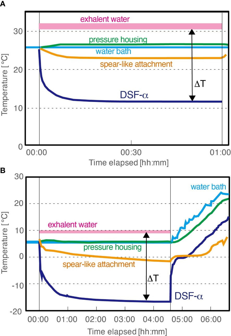
Figure 5 Temperature recorded during Assessment Test 3 of the DSF-α, laboratory-based tests with plastic insulation hull. (A) With water bath set to 25°C (seasurface temperature). (B) With water bath set to mimic the deep-sea condition: for the first 4 hours 30 mins the DSF-α was powered on and the water bath was set to 6°C and then the DSF-α was powered off and the water bath was allowed to gradually heat up to mimic temperature changes during the ROV recovery.
In the 6°C water setup in Test 3 mimicking the deep-sea condition, the entire DSF-α system was submerged in a 6°C water bath, with the cooling water supplied from an external chiller also set to 6°C (Figure 5B), while the other settings were same to the 25°C experiment. Temperatures monitored on the cold surface of the PD rapidly decreased to 0°C during the first minute of operation, then to -10°C after 18 minutes passed, and finally reached -16.6°C. Temperature monitored at the tip of the spear-like attachment slowly but steadily decreased to -2°C. A thin layer of ice began forming at the base of the spear-like attachment (i.e., the endothermic copper block of the DSF-α) after<10 minutes of operation; in the 270 minutes of continued operation the DSF-α produced approximately 1,000 mL of ice (Figure 6; Supplementary Movie 2). During growth of ice, the temperature between the pressure housing and the insulation hull was stable at 6°C, while the exhalent water was stable at 10°C. The electric current supplying the PD was almost stable at 5.7 A.
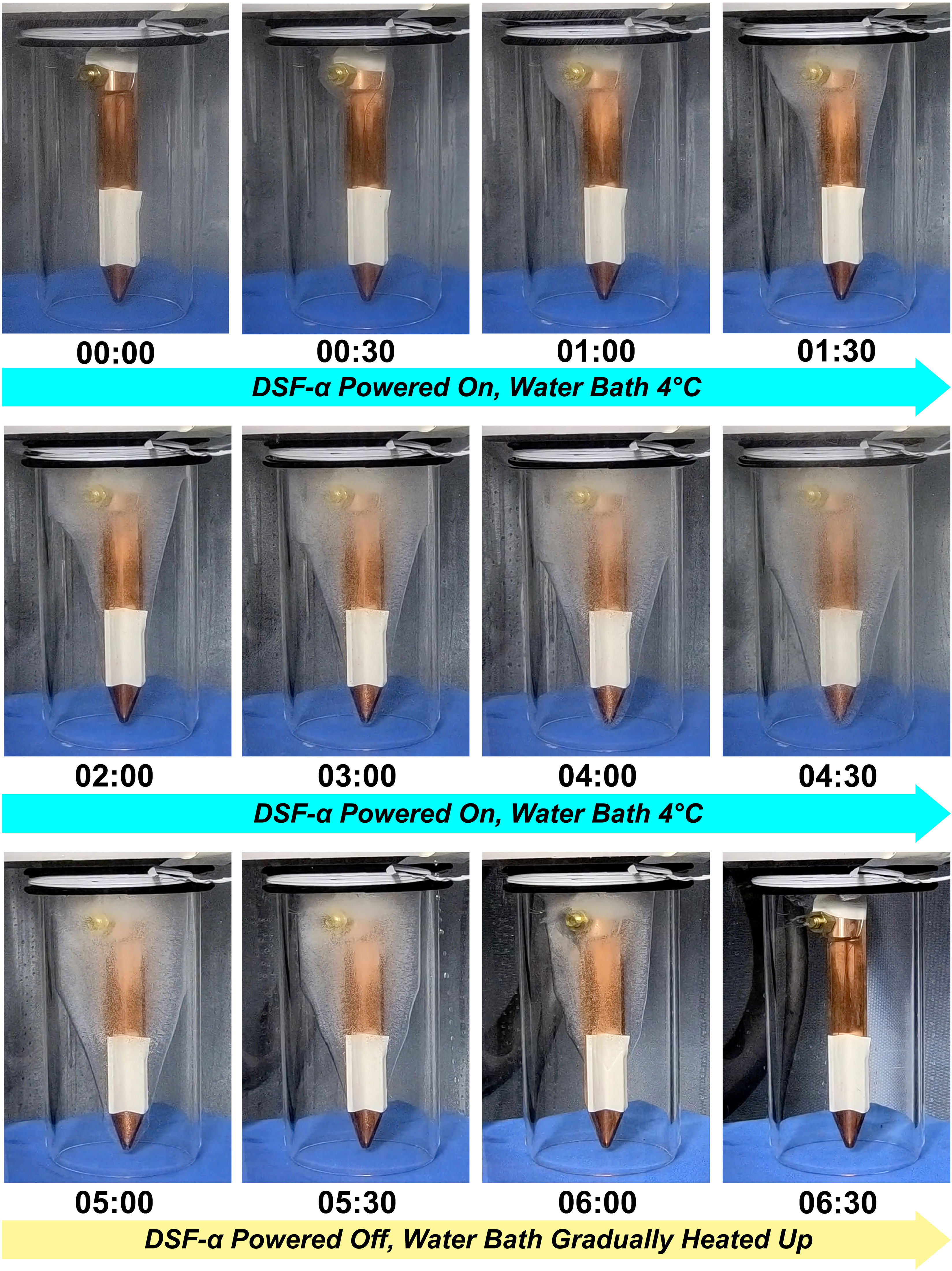
Figure 6 Process of ice formation during Assessment Test 3 mimicking the deep-sea condition (water bath set to 6°C) followed by a simulation of the ROV recovery, timestamps indicate time since the start of the experiment (hh:mm).
To simulate ice melting during the recovery of ROV through warm surface water, the DSF-α was shut down and then the water bath was gradually heated up. The ice was observed to gradually melted with time but visible ice remained in place for over two hours (Figure 6; Supplementary Movie 3). Immediately after shutting down the DSF-α, the cold surface of the PD rapidly increased to 0°C. During the heating of the water bath, temperatures at the cold surface of the PD steadily increased at -10K offset from the water bath temperature, while the pressure housing was offset by -3K. This implies the ice melted partly due to conductive heat transfer from the metal pressure housing of the DSF-α. The tip of the spear-shaped attachment remained around 0°C until the ice on the thermocouple melted, and gradually increased from then.
Discussion
Our prototype, DSF-α, successfully achieved in situ freezing in the deep sea and recovering ice mass on-board, serving as evidence that our concept, deep-sea freezing, is viable. Active, continuous cooling of the ‘hot’ side of the PD using ambient deep-sea water as well as passive cooling of the entire DSF-α body by ambient seawater was indeed sufficient to generate a temperature difference enough to generate ice on the ‘cool’ side of the PD. We consider the current device to be already useful for retrieving in situ frozen deep-sea samples for purposes such as proteomic analyses. On the other hand, the rate of freezing seems slow and would be not sufficient for preserving more labile molecules as is, such as mRNA for transcriptome analyses. Results from both our laboratory-based and field-based assessments point to heat transfer capability as the limitation from reaching lower temperatures and thus making more ice faster. To make the in situ freezing as a more useful sampling tool, the rate of freezing should be improved.
A possible improvement for the cooling capability of DSF is to use a multiple layer PD. A layered mount of multiple PDs is a commonly used method to more reduce the temperature at the ‘cool’ side of the PD as low as possible, according to the heat removal efficiency at the ‘hot’ side of the PD. Since the heat transfer mechanism of the DSF-α via pumping of the cool deep-sea water is capable of achieving sufficient heat removal from the ‘hot’ side, as shown by the heat budget evaluation in Test 1, the multiple layer PD will lead to achieving lower temperature and faster cooling at the ‘cool’ surface. Layering of PDs can be constructed by adjusting the electric wiring and length of props inside the DSF in order to hold multiple PDs (Figure 1, No. 16), the layered PDs are protected from the ambient pressure of the deep-sea environment just like the single PD in the DSF-α. Furthermore, although we used a peristaltic pump in the current design, a higher volume impeller pump may improve flushing of the heat sink and also consume less power.
Another possible improvement for the cooling mechanisms and rates of the DSF is by improving the insulation between the ‘cool’ side and the pressure housing. For simultaneous achievement of both pressure tolerance and heat conductivity, the endothermic copper is penetrated into the pressure housing. Such structure could have mediated conductive heat transfer between ambient seawater and endothermic sides of the PD via the pressure housing body and copper block. Although an insulation plate is built-in to the housing (Figure 1, No. 14) to mitigate this issue, this seems not sufficient and can be improved. The metal pressure housing is problematic, acting as a site of conductive heat transfer from the environment to the system. Improvement from a material point of view is difficult as there is currently few other available and suitable (non-metal) material for pressure housing combining similar levels of performance for both pressure tolerance and heat insulation. Nevertheless, we note that titanium is a more suitable material for the pressure housing due to its lower thermal conductivity compared to aluminium, though a clear disadvantage is that titanium is much more expensive. Tightly sealing the spaces between different parts with resin or similar material may improve the insulation, but it would make the maintenance more strenuous. We showed that adding a layer of insulation outside the housing improves the performance, indicating that improvement of exterior insulation by the means of an outer casing would likely further improve the performance.
The most plausible method to freeze deep-sea samples faster using the current version of DSF-α is the usage of multiple DSF-α devices for cooling a confined small volume space. For example, the ‘cool’ side of two or more DSF-α could be aligned to target a semi-enclosed space like an acrylic chamber. The target sample can be captured by suction sampler into the chamber and then relatively rapidly frozen by the simultaneous-operation of multiple DSF-α devices. Our laboratory-based simulation with cool ambient water (Figure 5B) demonstrates that two hours were needed to achieve 0°C at the tip of the spear-like attachment, despite the ‘cool’ surface of the PD reached -15°C immediately and ice formation at the root of the attachment began within 10 minutes. For instance, if two DSF-α devices are set face-to-face and in contact each other via highly conductive copper attachments, the space between the DSFs bridged by attachments will be cooled over twice as fast when compared to when just using a single device. A single DSF-α requires ~150 W (DC24V x ~6A) of power for operation, and thus power supply is a limitation for the concurrent operation of multiple DSF-α systems. The capacity of commercially available deep-sea batteries at the time of writing are typically between several hundreds to thousands Wh. As such, the operation of multiple DSF-α systems may be difficult for battery-based observatories such as landers (e.g. Oguri et al., 2016; Peoples et al., 2019), unless batteries with higher capacity can be sourced or the required operation time is short. This is however not an issue in the case of ROV use, where sufficient electric power can be supplied from the ship via cable.
The DSF-α is not only capable of freezing seawater, but is also able to cool down the surrounding environments, samples, or devices deployed at the deep-sea environment (without freezing). This has applicability in the field of experimental biology of deep-sea animals, where animals usually need to be acclimated for a long time (ideally two weeks) before experiment if collected and recovered from the seafloor without special provision (Sigwart and Chen, 2018). If the animal survives this process in the first place, that is – and time at sea is generally limited and do not allow for sufficient acclimation. Deep-sea animals are very sensitive to elevations in temperature, with many being physiologically unable to tolerate a few degrees of change (Childress and Girguis, 2011). Although more-or-less water-tight ‘bio boxes’ and suction sampler chambers have been constructed since the early days of deep-sea sciences, these are unable to completely insulate the animal contained from the changing water temperature during recovery (Sigwart and Chen, 2018). Using a device like the DSF-α to maintain the in situ temperature during recovery will improve the success rate of live animal experiments.
Conclusions
We propose the concept of a deep-sea freezer, using Peltier devices to form ice in situ in the deep sea in order to recover intact samples. Our prototype device, DSF-α, was indeed able to freeze seawater in situ, as well as recovering ice mass on deck. Assessment of the DSF-α in the deep sea using ROVs proved our concept by generating temperature as low as -13.0°C and successfully making the first literal ‘marine snow’ the deep has seen. We were also able to recover the frozen deep-sea ice on-board the research vessel, realising the transportation of frozen material from the deep sea to deep freezer in the lab without defrosting. As the DSF-α is based on a commercially available PD and is simple in construction, it is in principle easy to adopt and use. Our DSF-α is the first of its kind and only a prototype. We suggest some routes to advance the DSF and look to the future when a much-improved version of this prototype will be constructed, opening up a great diversity of applications in deep-sea research.
Data availability statement
The original contributions presented in the study are included in the article/Supplementary Material. Further inquiries can be directed to the corresponding author.
Author contributions
SK conceptualised and designed the study. YM and SK designed and participated in the construction of the DSF-α. SK, YM, HN, and CC carried out assessments of the deep-sea freezer. SK and CC interpreted the results and drafted the manuscript. All authors contributed to the manuscript and approved the final version for submission.
Funding
This work is partly supported by a JAMSTEC Innovation Award (2017). This work is partly based on results obtained from the research cruise KM21-E02 funded by the project JPNP18016, commissioned by the New Energy and Industrial Technology Development Organization (NEDO).
Acknowledgments
The DSF-α was constructed by Marine Works Japan Ltd. (Yokosuka, Japan), gratefully acknowledged here for their efforts towards producing this prototype device and their excellent service. Akiko Makabe kindly conducted ion chromatographic analysis. We thank the Captain and crew of R/Vs Shinsei-Maru and Kaimei as well as the pilots and the technical team of ROVs Hyper-Dolphin and KM-ROV during the expedition KS-20-J07 and KM21-E02 for their great support of scientific activity, especially in the difficult times of 2020 due to the COVID-19 pandemic. The deep-sea freezer would not have realised without the encouragement and reassurance from Ken Takai and Asahiko Taira, for which we are extremely grateful.
Conflict of interest
The authors declare that the research was conducted in the absence of any commercial or financial relationships that could be construed as a potential conflict of interest.
Publisher’s note
All claims expressed in this article are solely those of the authors and do not necessarily represent those of their affiliated organizations, or those of the publisher, the editors and the reviewers. Any product that may be evaluated in this article, or claim that may be made by its manufacturer, is not guaranteed or endorsed by the publisher.
Supplementary material
The Supplementary Material for this article can be found online at: https://www.frontiersin.org/articles/10.3389/fmars.2023.1179818/full#supplementary-material
Supplementary Video 1 | Time-lapse of the DSF-α during the in situ examination on-board ROV Hyper-Dolphin. Timestamps are in JST (Japan Standard Time). High resolution video available on Figshare: https://doi.org/10.6084/m9.figshare.22678015
Supplementary Video 2 | Time-lapse of ice formation during Assessment Test 3 mimicking the deep-sea condition, with the DSF-α powered on and water bath set to 6°C. The video is speeded up 10x. High resolution video available on Figshare: https://doi.org/10.6084/m9.figshare.22678015
Supplementary Video 3 | Time-lapse of ice melting during Assessment Test 3 (following on from ice formation in Supplementary Video 2), when the DSF-α was powered off and water bath was gradually heated up. The video is speeded up 10x. High resolution video available on Figshare: https://doi.org/10.6084/m9.figshare.22678015
References
Armstrong C. W., Foley N. S., Tinch R., van den Hove S. (2012). Services from the deep: steps towards valuation of deep sea goods and services. Ecosys. Serv. 2, 2–13. doi: 10.1016/j.ecoser.2012.07.001
Ashkenazy Y., Gildor H., Losch M., Macdonald F. A., Schrag D. P., Tziperman E. (2013). Dynamics of a snowball earth ocean. Nature 495, 90–93. doi: 10.1038/nature11894
Childress J. J., Girguis P. R. (2011). The metabolic demands of endosymbiotic chemoautotrophic metabolism on host physiological capacities. J. Exp. Biol. 214, 312–325. doi: 10.1242/jeb.049023
Drazen J. C., Sutton T. T. (2017). Dining in the deep: the feeding ecology of deep-sea fishes. Annu. Rev. Mar. Sci. 9, 337–366. doi: 10.1146/annurev-marine-010816-060543
Folkersen M. V., Fleming C. M., Hasan S. (2019). Depths of uncertainty for deep-sea policy and legislation. Global Environ. Change 54, 1–5. doi: 10.1016/j.gloenvcha.2018.11.002
Gentz T., Schlueter M. (2012). Underwater cryotrap-membrane inlet system (CT-MIS) for improved in situ analysis of gases. Limnol. Oceanogr.: Methods 10, 317–328. doi: 10.4319/lom.2012.10.317
Kyo M., Itoh T. (1994). “Fundamental experiment of thermoelectric module for the deep sea use,” in The Fifteenth Japan Symposium on Thermophysical Properties, Vol. B314 (Toyama, Japan: Japan Society of Thermophysical Properties). 469–472.
La Cono V., Smedile F., La Spada G., Arcadi E., Genovese M., Ruggeri G., et al. (2015). Shifts in the meso- and bathypelagic archaea communities composition during recovery and short-term handling of decompressed deep-sea samples. Environ. Microbiol. Rep. 7, 450–459. doi: 10.1111/1758-2229.12272
Oguri K., Furushima Y., Toyofuku T., Kasaya T., Wakita M., Watanabe S., et al. (2016). Long-term monitoring of bottom environments of the continental slope off otsuchi bay, northeastern Japan. J. Oceanogr. 72, 151–166. doi: 10.1007/s10872-015-0330-4
Peltier J. C. A. (1834). Nouvelles expériences sur la caloricité des courants électrique [New experiments on the heat effects of electric currents]. Annales Chimie Physique 56, 371–386.
Peoples L. M., Norenberg M., Price D., McGoldrick M., Novotny M., Bochdansky A., et al. (2019). A full-ocean-depth rated modular lander and pressure-retaining sampler capable of collecting hadal-endemic microbes under in situ conditions. Deep Sea Res. Part I 143, 50–57. doi: 10.1016/j.dsr.2018.11.010
Sigwart J. D., Chen C. (2018). Comparative oxygen consumption of gastropod holobionts from deep-Sea hydrothermal vents in the Indian Ocean. Biol. Bull. 235, 102–112. doi: 10.1086/699326
Keywords: in situ freezing, thermoelectric cooling, Peltier device, sample preservation, deep-sea ice
Citation: Kawagucci S, Matsui Y, Nomaki H and Chen C (2023) Deep-sea freezer. Front. Mar. Sci. 10:1179818. doi: 10.3389/fmars.2023.1179818
Received: 04 March 2023; Accepted: 14 April 2023;
Published: 27 April 2023.
Edited by:
Erik Cordes, Temple University, United StatesReviewed by:
Santiago Herrera, Lehigh University, United StatesDongsheng Zhang, Ministry of Natural Resources, China
Peter R. Girguis, Harvard University, United States
Copyright © 2023 Kawagucci, Matsui, Nomaki and Chen. This is an open-access article distributed under the terms of the Creative Commons Attribution License (CC BY). The use, distribution or reproduction in other forums is permitted, provided the original author(s) and the copyright owner(s) are credited and that the original publication in this journal is cited, in accordance with accepted academic practice. No use, distribution or reproduction is permitted which does not comply with these terms.
*Correspondence: Shinsuke Kawagucci, a2F3YWd1Y2NpQGphbXN0ZWMuZ28uanA=
†These authors have contributed equally to this work